2017 MERCEDES-BENZ GLE COUPE Compressor
[x] Cancel search: CompressorPage 313 of 366

XWhen the tire pressure is correct, unscrew the
filler hose from the valve of the sealed tire.
XScrew the valve cap onto the tire valve of the
sealed tire.
XPull the tire sealant bottle out of the tire infla-
tion compressor.
The filler hose remains attached to the tire
sealant bottle.
XDrive to the nearest qualified specialist work-
shop and have the tire changed there.
XHave the tire sealant bottle replaced as soon
as possible at a qualified specialist workshop.
XHave the tire sealant bottle replaced every
four years at a qualified specialist workshop.
Battery (vehicle)
12 V battery - important safety notes
Special tools and expert knowledge are required
when working on the battery, e.g. removal and
installation. You should therefore have all work
involving the battery carried out at a qualified
specialist workshop.
GWARNING
Work carried out incorrectly on the battery
can lead, for example, to a short circuit and
thus damage the vehicle electronics. This can
lead to function restrictions applying to
safety-relevant systems, e.g the lighting sys-
tem, the ABS (anti-lock braking system) or the
ESP
®(Electronic Stability Program). The oper-
ating safety of your vehicle may be restricted.
You could lose control of the vehicle, for
example:
Rwhen braking
Rin the event of abrupt steering maneuvers
and/or when the vehicle's speed is not
adapted to the road conditions
There is a risk of an accident.
In the event of a short circuit or a similar inci-
dent, contact a qualified specialist workshop
immediately. Do not drive any further. You
should have all work involving the battery car- ried out at a qualified specialist workshop. For further information about ABS and ESP
®,
see (Ypage 61) and (Ypage 64).
GWARNING
Electrostatic build-up can lead to the creation of sparks, which could ignite the highly explo-
sive gases of a battery. There is a risk of an
explosion.
Before handling the battery, touch the vehicle
body to remove any existing electrostatic
build-up.
The highly flammable gas mixture forms when
charging the battery as well as when jump-start-
ing.
Always make sure that neither you nor the bat-
tery is electrostatically charged. A build-up of
electrostatic charge can be caused, for exam-
ple:
Rby wearing clothing made from synthetic
fibers
Rdue to friction between clothing and seats
Rif you push or pull the battery across the car-
pet or other synthetic materials
Rif you wipe the battery with a cloth
GWARNING
During the charging process, a battery produ-
ces hydrogen gas. If a short circuit occurs or
sparks are created, the hydrogen gas can
ignite. There is a risk of an explosion.
RMake sure that the positive terminal of a
connected battery does not come into con- tact with vehicle parts.
RNever place metal objects or tools on a bat-
tery.
RIt is important that you observe the descri-
bed order of the battery terminals when
connecting and disconnecting a battery.
RWhen jump-starting, make sure that the
battery poles with identical polarity are
connected.
RIt is particularly important to observe the
described order when connecting and dis-
connecting the jumper cables.
RNever connect or disconnect the battery
terminals while the engine is running.
Battery (vehicle)311
Breakdown assistance
Z
Page 347 of 366

Lowering the vehicle
GWARNING
The wheels could work loose if the wheel nuts and bolts are not tightened to the specified
tightening torque. There is a risk of accident.
Have the tightening torque immediately
checked at a qualified specialist workshop
after a wheel is changed.
!Mercedes-AMG vehicles with a collapsi-
ble spare wheel: before lowering the vehicle,
inflate the collapsible spare wheel with the
tire inflation compressor. The wheel rim could
otherwise be damaged.
XPlace the ratchet wrench onto the hexagon
nut of the jack so that the letters ABare visi-
ble.
XTurn the ratchet wrench until the vehicle is
once again standing firmly on the ground.
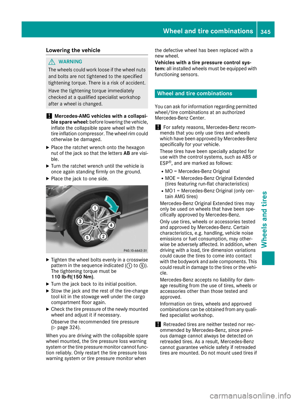
XPlace the jack to one side.
XTighten the wheel bolts evenly in a crosswise pattern in the sequence indicated (: toA).
The tightening torque must be
110 lb-f t(150 Nm).
XTurn the jack back to its initial position.
XStow the jack and the rest of the tire-change
tool kit in the stowage well under the cargo
compartment floor again.
XCheck the tire pressure of the newly mounted
wheel and adjust it if necessary.
Observe the recommended tire pressure
(
Ypage 324).
When you are driving with the collapsible spare
wheel mounted, the tire pressure loss warning
system or the tire pressure monitor cannot func-
tion reliably. Only restart the tire pressure loss
warning system or tire pressure monitor when the defective wheel has been replaced with a
new wheel.
Vehicles with a tire pressure control sys-
tem:
all installed wheels must be equipped with
functioning sensors.
Wheel and tire combinations
You can ask for information regarding permitted
wheel/tire combinations at an authorized
Mercedes-Benz Center.
!For safety reasons, Mercedes-Benz recom-
mends that you only use tires and wheels
which have been approved by Mercedes-Benz
specifically for your vehicle.
These tires have been specially adapted for
use with the control systems, such as ABS or
ESP
®, and are marked as follows:
RMO = Mercedes-Benz Original
RMOE = Mercedes-Benz Original Extended
(tires featuring run-flat characteristics)
RMO1 = Mercedes-Benz Original (only cer-
tain AMG tires)
Mercedes-Benz Original Extended tires may
only be used on wheels that have been spe-
cifically approved by Mercedes-Benz.
Only use tires, wheels or accessories tested
and approved by Mercedes-Benz. Certain
characteristics, e.g. handling, vehicle noise
emissions or fuel consumption, may other-
wise be adversely affected. In addition, when
driving with a load, tire dimension variations
could cause the tires to come into contact
with the bodywork and axle components. This
could result in damage to the tires or the vehi- cle.
Mercedes-Benz accepts no liability for dam-
age resulting from the use of tires, wheels or
accessories other than those tested and
approved.
Information on tires, wheels and approved
combinations can be obtained from any quali-
fied specialist workshop.
!Retreaded tires are neither tested nor rec-
ommended by Mercedes-Benz, since previ-
ous damage cannot always be detected on
retreaded tires. As a result, Mercedes-Benz
cannot guarantee vehicle safety if retreaded
tires are mounted. Do not mount used tires if
Wheel and tire combinations345
Wheels and tires
Z
Page 351 of 366

Inflating the collapsible spare wheel
(Mercedes-AMG GLE 63)
!
Inflat eth ecollapsible spar ewhee lusin gth e
tire inflation compressor before lowering th e
vehicle. The whee lrim could otherwise be
damaged.
!Do no toperate th etire inflation compressor
for longer than eigh tminute sat atime without
a break. It may otherwise overheat.
The tire inflation compressor can be operate d
again once it has cooled down .
Comply wit hth emanufacturer' ssafet yinstruc-
tion son th etire inflation compressor label and
on th etire sealan tbottle.
XMoun tth ecollapsible spar ewhee las descri-
bed (Ypage 341).
The collapsible spar ewhee lmust be mounte d
before it is inflated.
XRemove th etire inflation compressor from
th estowage spac eunder th etrunk floor
(
Ypage 306).
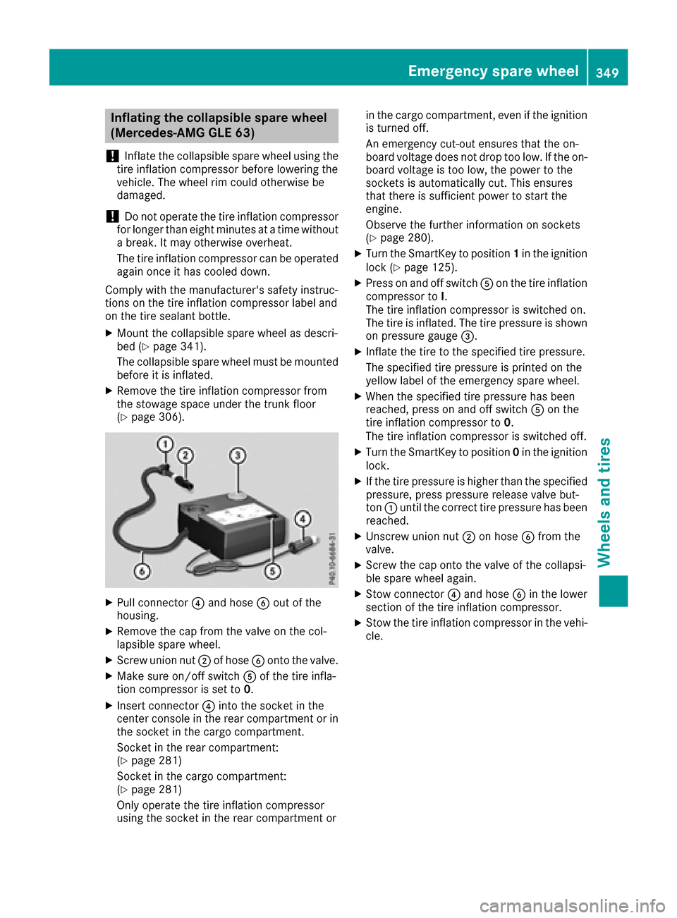
XPull connecto r? and hos eB out of th e
housing .
XRemove th ecap from th evalv eon th ecol-
lapsible spar ewheel.
XScrew unio nnut ;of hos eB onto th evalve.
XMak esur eon/off switch Aof th etire infla-
tion compressor is set to 0.
XInsertconnecto r? intoth esocke tin th e
center console in th erear compartmen tor in
th esocke tin th ecargo compartment.
Socket in th erear compartment:
(
Ypage 281)
Socket in th ecargo compartment:
(
Ypage 281)
Only operate th etire inflation compressor
usin gth esocke tin th erear compartmen tor in th
ecargo compartment, eve nif th eignition
is turne doff .
An emergenc ycut-out ensures that th eon -
boar dvoltag edoes no tdro pto olow. If th eon -
boar dvoltag eis to olow, th epower to th e
sockets is automatically cut .This ensures
that there is sufficien tpower to start th e
engine.
Observ eth efurther information on sockets
(
Ypage 280).
XTurn th eSmartKey to position 1in th eignition
loc k (Ypage 125).
XPress on and off switch Aon th etire inflation
compressor to I.
The tire inflation compressor is switched on .
The tire i
s inflated. The tire pressur eis shown
on pressur egauge =.
XInflateth etire to th especifie dtire pressure.
The specifie dtire pressur eis printe don th e
yellow label of th eemergenc yspar ewheel.
XWhen th especifie dtire pressur ehas been
reached, press on and off switch Aon th e
tire inflation compressor to 0.
The tire inflation compressor is switched off .
XTurn theSmartKey to position 0in th eignition
lock.
XIf th etire pressur eis higher than th especifie d
pressure, press pressur erelease valv ebut -
to n: until th ecorrec ttire pressur ehas been
reached.
XUnscrew unio nnut ;on hos eB from th e
valve.
XScrew th ecap onto th evalv eof th ecollapsi-
ble spar ewhee lagain .
XStow connecto r? and hos eB in th elower
section of th etire inflation compressor.
XStow th etire inflation compressor in th evehi-
cle .
Emergency spare wheel349
Wheels and tires
Z