2017 MERCEDES-BENZ GLE COUPE Start
[x] Cancel search: StartPage 332 of 366
In addition to the warning lamp, a message
appears in the multifunction display. Observe
the information on display messages
(
Ypage 244).
It may take up to ten minutes for a malfunction of the tire pressure monitor to be indicated. A
malfunction will be indicated by the tire pres-
sure warning lamp flashing for approximately
one minute and then remaining lit. When the
malfunction has been rectified, the tire pressure
warning lamp goes out after a few minutes of
driving.
The tire pressure values indicated by the on-
board computer may differ from those meas-
ured at a gas station with a pressure gauge. The
tire pressures shown by the on-board computer
refer to those measured at sea level. At high
altitudes, the tire pressure values indicated by a
pressure gauge are higher than those shown by the on-board computer. In this case, do not
reduce the tire pressures.
The operation of the tire pressure monitor can
be affected by interference from radio transmit-
ting equipment (e.g. radio headphones, two-way
radios) that may be being operated in or near the vehicle.
Checking the tire pressure electroni-
cally
XMake sure that the SmartKey is in position 2
in the ignition lock (Ypage 125).
XPress the =or; button on the steering
wheel to select the Serv.menu.
XPress the9or: button to select
Tire Pressure.
XPress the abutton.
The current tire pressure of each tire is shown
in the multifunction display.
If the vehicle has been parked for longer than
20 minutes, the Tire pressure will be
displayed after driving a few minutesmessage appears.
After a teach-in process, the tire pressure mon-
itor automatically detects new wheels or new
sensors. As long as a clear allocation of the tire
pressure value to the individual wheels is not
possible, theTire
PressureMonitorActivedisplay message is shown instead of the tire
pressure display. The tire pressures are already
being monitored.
If an emergency spare wheel is mounted, the
system may continue to show the tire pressure of the wheel that has been removed for a few
minutes. If this occurs, note that the value dis-
played for the position where the spare wheel is
mounted is not the same as the current tire
pressure of the emergency spare wheel.
Tire pressure monitor warning mes-
sages
If the tire pressure monitor detects a pressure
loss in one or more tires, a warning message is
shown in the multifunction display. The yellow
tire pressure warning lamp then lights up.
RIf the
Please Correct Tire Pressuremessage appears in the multifunction display,
the tire pressure in at least one tire is too low.
The tire pressure must be corrected when the
opportunity arises.
RIf theCheck Tiresmessage appears in the
multifunction display, the tire pressure in at
least one tire has dropped significantly. The
tires must be checked.
RIf the WarningTireMalfunctionmessage
appears in the multifunction display, the tire
pressure in at least one tire has dropped sud- denly. The tires must be checked.
Be sure to observe the instructions and safety
notes in the display messages in the "Tires" sec-
tion (
Ypage 244).
If the wheel positions on the vehicle are rotated, the tire pressures may be displayed for the
wrong positions for a short time. This is rectified
after a few minutes of driving, and the tire pres-
sures are displayed for the correct positions.
Restarting the tire pressure monitor
When you restart the tire pressure monitor, all
existing warning messages are deleted and the
warning lamps go out. The monitor uses the cur-
rently set tire pressures as the reference values
for monitoring. In most cases, the tire pressure
monitor will automatically detect the new refer-
ence values after you have changed the tire
pressure. However, you can also define refer-
ence values manually as described here. The tire
pressure monitor then monitors the new tire
pressure values.
XSet the tire pressure to the value recommen-
ded for the corresponding driving situation on
the Tire and Loading Information placard on
the driver's side B-pillar (
Ypage 324).
330Tire pressure
Wheels and tires
Page 333 of 366
You can find more tire pressure values for
various operating conditions in the tire pres-
sure table inside the fuel filler flap
(
Ypage 324).
XMake sure that the tire pressure is correct on
all four wheels.
XMake sure that the SmartKey is in position2
in the ignition lock.
XPress the =or; button on the steering
wheel to select the Serv.menu.
XPress the9or: button to select
Tire Pressure.
XPress the abutton.
The multifunction display shows the current
tire pressure for the individual tires or the
Tire pressure will be displayed
after driving a few minutesmessage.
XPress the :button.
The UseCurrentPressuresasNewRef‐erenceValuesmessage appears in the mul-
tifunction display.
If you wish to confirm the restart:
XPress the abutton.
The TirePress.MonitorRestartedmes-
sage appears in the multifunction display.
After driving for a few minutes, the system
checks whether the current tire pressures are
within the specified range. The new tire pres-
sures are then accepted as reference values
and monitored.
If you wish to cancel the restart:
XPress the %button.
The tire pressure values stored at the last
restart will continue to be monitored.
Radio type approval for the tire pres-
sure monitor
CountryRadio type approval number
USAFCC ID: MRXMW2433A
FCC ID: MRXGG4
FCC ID: MRXMC34MA4
CanadaIC: 2546A-MW2433A
IC: 2546A-GG4
IC: 2546A-MC34MA4
Loading the vehicle
Instruction labels for tires and loads
GWARNING
Overloaded tires can overheat, causing a
blowout. Overloaded tires can also impair the steering and driving characteristics and lead
to brake failure. There is a risk of accident.
Observe the load rating of the tires. The load
rating must be at least half of the GAWR of
your vehicle. Never overload the tires by
exceeding the maximum load.
Two instruction labels on your vehicle show the maximum possible load.
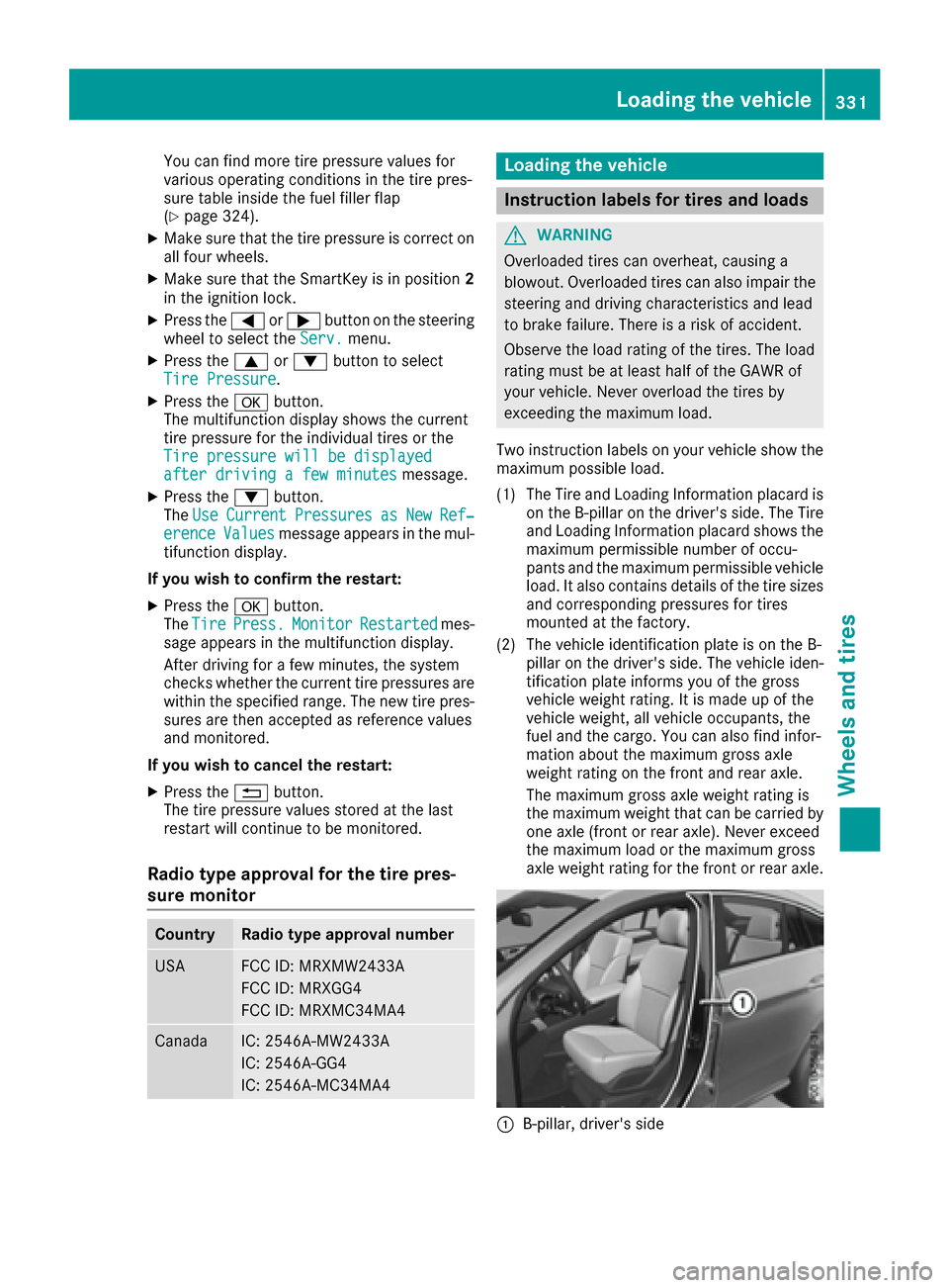
(1) The Tire and Loading Information placard is on the B-pillar on the driver's side. The Tire
and Loading Information placard shows the
maximum permissible number of occu-
pants and the maximum permissible vehicle
load. It also contains details of the tire sizes
and corresponding pressures for tires
mounted at the factory.
(2) The vehicle identification plate is on the B- pillar on the driver's side. The vehicle iden-
tification plate informs you of the gross
vehicle weight rating. It is made up of the
vehicle weight, all vehicle occupants, the
fuel and the cargo. You can also find infor-
mation about the maximum gross axle
weight rating on the front and rear axle.
The maximum gross axle weight rating is
the maximum weight that can be carried by
one axle (front or rear axle). Never exceed
the maximum load or the maximum gross
axle weight rating for the front or rear axle.
:B-pillar, driver's side
Loading the vehicle331
Wheels and tires
Z
Page 340 of 366
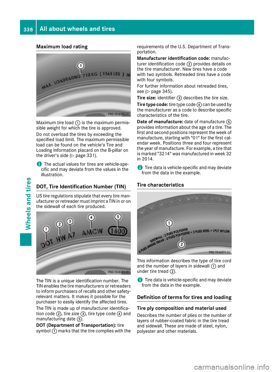
Maximum load rating
Maximum tire load:is the maximum permis-
sible weight for which the tire is approved.
Do not overload the tires by exceeding the
specified load limit. The maximum permissible
load can be found on the vehicle's Tire and
Loading Information placard on the B-pillar on
the driver's side (
Ypage 331).
iThe actual values for tires are vehicle-spe-
cific and may deviate from the values in the
illustration.
DOT, Tire Identification Number (TIN)
US tire regulations stipulate that every tire man-
ufacturer or retreader must imprint a TIN in or on
the sidewall of each tire produced.
The TIN is a unique identification number. The
TIN enables the tire manufacturers or retreaders
to inform purchasers of recalls and other safety-
relevant matters. It makes it possible for the
purchaser to easily identify the affected tires.
The TIN is made up of manufacturer identifica-
tion code ;, tire size =, tire type code ?and
manufacturing date A.
DOT (Department of Transportation): tire
symbol :marks that the tire complies with the requirements of the U.S. Department of Trans-
portation.
Manufacturer identification code:
manufac-
turer identification code ;provides details on
the tire manufacturer. New tires have a code
with two symbols. Retreaded tires have a code
with four symbols.
For further information about retreaded tires,
see (
Ypage 345).
Tire size: identifier=describes the tire size.
Tire type code: tire type code?can be used by
the manufacturer as a code to describe specific
characteristics of the tire.
Date of manufacture: date of manufactureA
provides information about the age of a tire. The
first and second positions represent the week of
manufacture, starting with "01" for the first cal-
endar week. Positions three and four represent
the year of manufacture. For example, a tire that
is marked "3214" was manufactured in week 32
in 2014.
iTire data is vehicle-specific and may deviate
from the data in the example.
Tire characteristics
This information describes the type of tire cord
and the number of layers in sidewall :and
under tire tread ;.
iTire data is vehicle-specific and may deviate
from the data in the example.
Definition of terms for tires and loading
Tire ply composition and material used
Describes the number of plies or the number of
layers of rubber-coated fabric in the tire tread
and sidewall. These are made of steel, nylon,
polyester and other materials.
338All about wheels and tires
Wheels and tires
Page 343 of 366
Changing a wheel
Flat tire
The "Breakdown assistance" section
(Ypage 306) contains information and notes on
how to deal with a flat tire. Information on driv-
ing with MOExtended tires in the event of a flat
tire can be found under "MOExtended tires (tires
with run-flat characteristics" (
Ypage 307).
Vehicles with an emergency spare wheel: in
the event of a flat tire, mount the emergency
spare wheel according to the description under "Mounting a wheel" (
Ypage 341).
Rotating the wheels
GWARNING
Interchanging the front and rear wheels may
severely impair the driving characteristics if
the wheels or tires have different dimensions. The wheel brakes or suspension components
may also be damaged. There is a risk of acci-
dent.
Rotate front and rear wheels only if the wheels and tires are of the same dimensions.
!On vehicles equipped with a tire pressure
monitor, electronic components are located
in the wheel.
Tire-mounting tools should not be used near
the valve. This could damage the electronic
components.
Only have tires changed at a qualified spe-
cialist workshop.
Always observe the instructions and safety
notes in the "Mounting a wheel" section
(
Ypage 341).
The wear patterns on the front and rear tires
differ, depending on the operating conditions.
Rotate the wheels before a clear wear pattern
has formed on the tires. Front tires typically
wear more on the shoulders and the rear tires in
the center.
On vehicles that have the same size front and
rear wheels, you can rotate the wheels accord-
ing to the intervals in the tire manufacturer's
warranty book in your vehicle documents. If no
warranty book is available, the tires should be
rotated every 3,000 to 6,000 miles (5,000to
10,
000 km). Depending on tire wear, this may be required earlier. Do not change the direction
of wheel rotation.
Clean the contact surfaces of the wheel and the
brake disc thoroughly every time a wheel is rota-
ted. Check the tire pressure and, if necessary,
restart the tire pressure loss warning system or
the tire pressure monitor (
Ypage 328).
Direction of rotation
Tires with a specified direction of rotation have
additional benefits, e.g. if there is a risk of hydro-
planing. These advantages can only be gained if
the tires are installed corresponding to the
direction of rotation.
An arrow on the sidewall of the tire indicates its
correct direction of rotation.
Storing wheels
Store wheels that are not being used in a cool,
dry and preferably dark place. Protect the tires
from oil, grease, gasoline and diesel.
Mounting a wheel
Preparing the vehicle
XVehicle with emergency spare wheel:
when mounting the emergency spare wheel in
the event of a flat tire, follow the additional
notes on vehicle preparation under "Flat tire"
(
Ypage 306).
XStop the vehicle on solid, non-slippery and
level ground.
XApply the electric parking brake manually.
XBring the front wheels into the straight-ahead position.
XVehicles with automatic transmission:
shift the automatic transmission to position
P .
XVehicles with the AIRMATIC package:
make sure that the normal vehicle level is
selected (
Ypage 171).
XSwitch off the engine.
XVehicles without KEYLESS-GO: remove the
SmartKey from the ignition lock.
Changing a wheel341
Wheels an d tires
Z
Page 344 of 366

XVehicles with KEYLESS-GO:open the driv-
er's door.
The on-board electronics now have status 0.
This is the same as the SmartKey having been
removed.
XVehicles with KEYLESS-GO: remove the
Start/Stop button from the ignition lock
(
Ypage 125).
XMake sure that the engine cannot be started
via your smartphone (Ypage 127).
XIf included in the vehicle equipment, remove
the tire-change tool kit from the vehicle.
XSafeguard the vehicle against rolling away.
iApart from certain country-specific varia-
tions, vehicles are not equipped with a tire-
change tool kit. For information on which
tools are required to perform a wheel change
on your vehicle, consult an authorized
Mercedes-Benz Center.
Necessary tire-changing tools can include, for example:
RJack
RWheel chock
RLug wrench
Securing the vehicle to prevent it from
rolling away
If your vehicle is equipped with a wheel chock, itcan be found in the tire-change tool kit
(
Ypage 306).
The folding wheel chock is an additional safety
measure to prevent the vehicle from rolling
away, for example when changing a wheel.
XFold both plates upwards :.
XFold out lower plate;.
XGuide the lugs on the lower plate fully into the
openings in base plate =.
XPlace chocks or other suitable items under
the front and rear of the wheel that is diago-
nally opposite the wheel you wish to change.
Raising the vehicle
GWARNING
If you do not position the jack correctly at the
appropriate jacking point of the vehicle, the
jack could tip over with the vehicle raised.
There is a risk of injury.
Only position the jack at the appropriate jack-
ing point of the vehicle. The base of the jack
must be positioned vertically, directly under
the jacking point of the vehicle.
!The jack is designed exclusively for jacking
up the vehicle at the jacking points. Other-
wise, your vehicle could be damaged.
Observe the following when raising the vehi-
cle:
RTo raise the vehicle, only use the vehicle-spe-
cific jack that has been tested and approved
by Mercedes-Benz. If used incorrectly, the
jack could tip over with the vehicle raised.
RThe jack is designed only to raise and hold the
vehicle for a short time while a wheel is being
changed. It must not be used for performing
maintenance work under the vehicle.
RAvoid changing the wheel on uphill and down- hill slopes.
RBefore raising the vehicle, secure it from roll-
ing away by applying the parking brake and
inserting wheel chocks. Do not disengage the
parking brake while the vehicle is raised.
RThe jack must be placed on a firm, flat and
non-slip surface. On a loose surface, a large,
flat, load-bearing underlay must be use
d. On a
342Changing a wheel
Wheels and tires
Page 345 of 366

slippery surface, a non-slip underlay must be
used, e.g. rubber mats.
RDo not use wooden blocks or similar objects
as a jack underlay. Otherwise, the jack will notbe able to achieve its load-bearing capacity
due to the restricted height.
RMake sure that the distance between the
underside of the tires and the ground does not
exceed 1.2 in (3 cm).
RDo not place your hands or feet under the
raised vehicle.
RDo not lie under the vehicle.
RDo not start the engine when the vehicle is
raised.
RNever open or close a door or the tailgate
when the vehicle is raised.
RMake sure that no persons are present in the
vehicle when the vehicle is raised.
XUsing lug wrench :, loosen the bolts on the
wheel you wish to change by about one full
turn. Do not unscrew the bolts completely.
The jacking points are located just behind the
front wheel housings and just in front of the rear
wheel housings (arrows).
XTake the ratchet wrench out of the vehicle
tool kit and place it on the hexagon nut of the
jack so that the letters AUFare visible.
XPosition jack =at jacking point ;.
XMake sure the foot of the jack is directly
beneath the jacking point.
XTurn ratchet wrench ?until jack =sits
completely on jacking point ;and the base
of the jack lies evenly on the ground.
XTurn ratchet wrench ?until the tire is raised
a maximum of 1.2 in (3 cm) from the ground.
Removing a wheel
!Do not place wheel bolts in sand or on a dirty
surface. The bolt and wheel hub threads could
otherwise be damaged when you screw them
in.
When mounting/removing wheels, and for as
long as the wheels are removed, avoid applying
any external force on the brake disks. This could impair the level of comfort when braking.
Changing a wheel343
Wheels and tires
Z
Page 347 of 366
Lowering the vehicle
GWARNING
The wheels could work loose if the wheel nuts and bolts are not tightened to the specified
tightening torque. There is a risk of accident.
Have the tightening torque immediately
checked at a qualified specialist workshop
after a wheel is changed.
!Mercedes-AMG vehicles with a collapsi-
ble spare wheel: before lowering the vehicle,
inflate the collapsible spare wheel with the
tire inflation compressor. The wheel rim could
otherwise be damaged.
XPlace the ratchet wrench onto the hexagon
nut of the jack so that the letters ABare visi-
ble.
XTurn the ratchet wrench until the vehicle is
once again standing firmly on the ground.
XPlace the jack to one side.
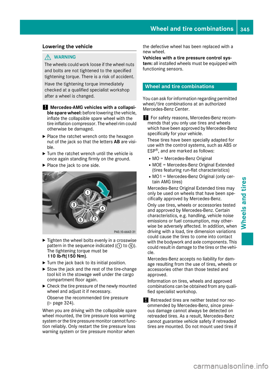
XTighten the wheel bolts evenly in a crosswise pattern in the sequence indicated (: toA).
The tightening torque must be
110 lb-f t(150 Nm).
XTurn the jack back to its initial position.
XStow the jack and the rest of the tire-change
tool kit in the stowage well under the cargo
compartment floor again.
XCheck the tire pressure of the newly mounted
wheel and adjust it if necessary.
Observe the recommended tire pressure
(
Ypage 324).
When you are driving with the collapsible spare
wheel mounted, the tire pressure loss warning
system or the tire pressure monitor cannot func-
tion reliably. Only restart the tire pressure loss
warning system or tire pressure monitor when the defective wheel has been replaced with a
new wheel.
Vehicles with a tire pressure control sys-
tem:
all installed wheels must be equipped with
functioning sensors.
Wheel and tire combinations
You can ask for information regarding permitted
wheel/tire combinations at an authorized
Mercedes-Benz Center.
!For safety reasons, Mercedes-Benz recom-
mends that you only use tires and wheels
which have been approved by Mercedes-Benz
specifically for your vehicle.
These tires have been specially adapted for
use with the control systems, such as ABS or
ESP
®, and are marked as follows:
RMO = Mercedes-Benz Original
RMOE = Mercedes-Benz Original Extended
(tires featuring run-flat characteristics)
RMO1 = Mercedes-Benz Original (only cer-
tain AMG tires)
Mercedes-Benz Original Extended tires may
only be used on wheels that have been spe-
cifically approved by Mercedes-Benz.
Only use tires, wheels or accessories tested
and approved by Mercedes-Benz. Certain
characteristics, e.g. handling, vehicle noise
emissions or fuel consumption, may other-
wise be adversely affected. In addition, when
driving with a load, tire dimension variations
could cause the tires to come into contact
with the bodywork and axle components. This
could result in damage to the tires or the vehi- cle.
Mercedes-Benz accepts no liability for dam-
age resulting from the use of tires, wheels or
accessories other than those tested and
approved.
Information on tires, wheels and approved
combinations can be obtained from any quali-
fied specialist workshop.
!Retreaded tires are neither tested nor rec-
ommended by Mercedes-Benz, since previ-
ous damage cannot always be detected on
retreaded tires. As a result, Mercedes-Benz
cannot guarantee vehicle safety if retreaded
tires are mounted. Do not mount used tires if
Wheel and tire combinations345
Wheels and tires
Z
Page 349 of 366
tion reliably. Only restart the tire pressure loss
warning system or tire pressure monitor when
the defective wheel has been replaced with a
new wheel.
Vehicles with tire pressure monitor:after
mounting an emergency spare wheel, the sys-
tem may still display the tire pressure of the
removed wheel for a few minutes. The value dis-
played for the mounted emergency spare wheel
is not the same as the current tire pressure of
the emergency spare wheel.
Removing/stowing the emergency
spare wheel
Vehicles with a "Minispare" emergency
spare wheel under the cargo compart-
ment floor
Always observe the instructions and safety
notes in the "Mounting a wheel" section
(
Ypage 341).
The "Minispare" emergency spare wheel can be
found in the stowage well under the cargo com-
partment floor.
Removing the emergency spare wheel
XLift the cargo compartment floor upwards
(Ypage 276).
XTurn retaining screw ;counter-clockwise
and remove it.
XRemove "Minispare" emergency spare
wheel :.
Vehicles with a "Minispare" emergency
spare wheel in the emergency spare
wheel bag
Always observe the instructions and safety
notes in the "Mounting a wheel" section
(
Ypage 341).
On vehicles with a Bang & Olufsen sound sys-
tem, the "Minispare" emergency spare wheel is packed in an emergency spare wheel bag. The
emergency spare wheel bag is secured to the
cargo tie-down rings in the cargo compartment.
Removing the emergency spare wheel
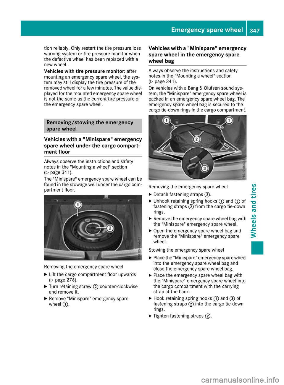
XDetach fastening straps ;.
XUnhook retaining spring hooks :and =of
fastening straps ;from the cargo tie-down
rings.
XRemove the emergency spare wheel bag with
the "Minispare" emergency spare wheel.
XOpen the emergency spare wheel bag and
remove the "Minispare" emergency spare
wheel.
Stowing the emergency spare wheel
XPlace the "Minispare" emergency spare wheel
into the emergency spare wheel bag and
close the emergency spare wheel bag.
XPlace the emergency spare wheel bag with
the "Minispare" emergency spare wheel into
the cargo compartment with the carrying
strap at the back.
XHook retaining spring hooks :and =of
fastening straps ;into the cargo tie-down
rings.
XTighten fastening straps ;.
Emergency sparewheel347
Wheels an d tires
Z