2017 MERCEDES-BENZ GLC SUV stowage compartment
[x] Cancel search: stowage compartmentPage 290 of 374
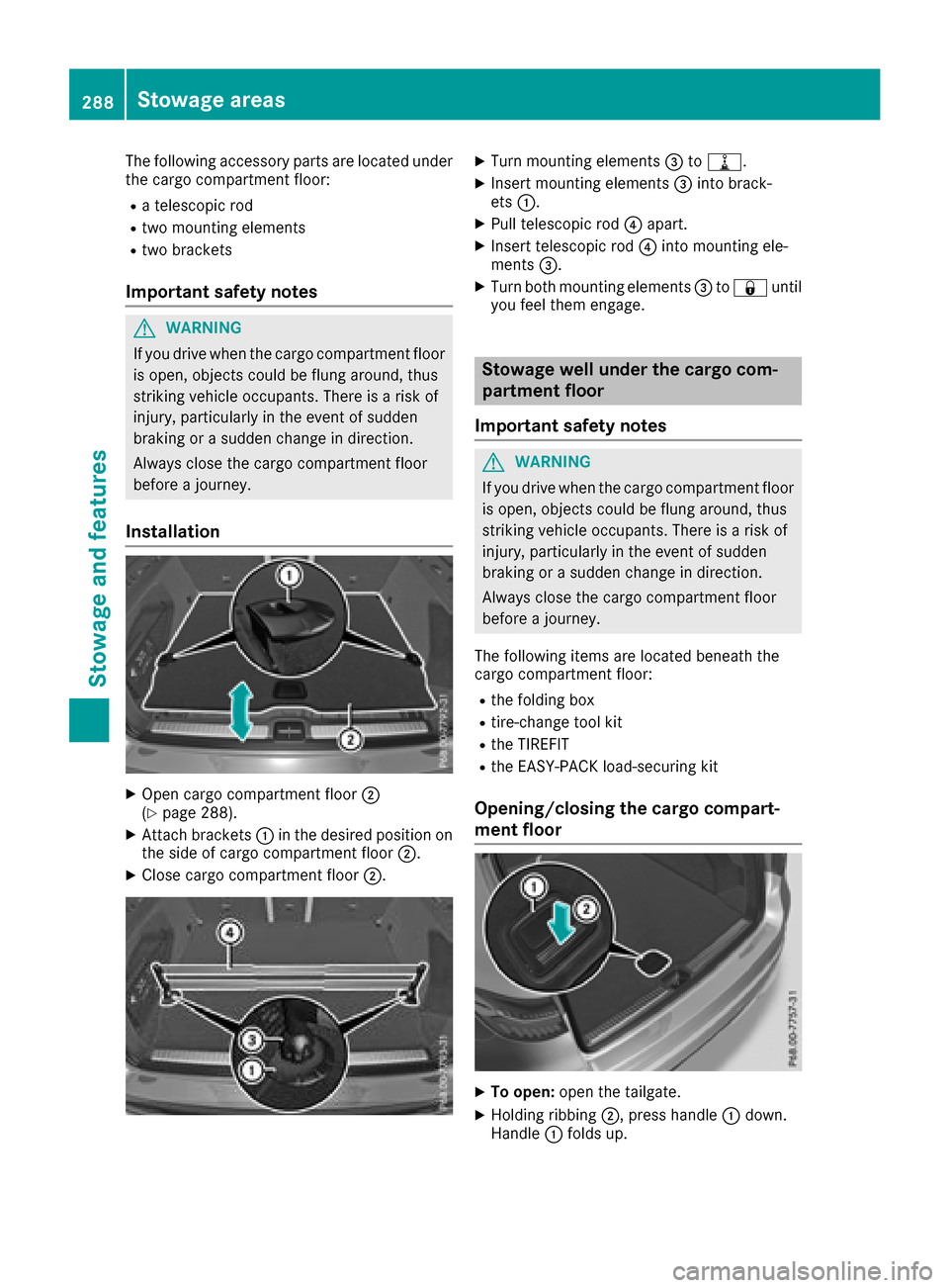
The following accessory parts are located under
the cargo compartment floor:
Ra telescopic rod
Rtwo mounting elements
Rtwo brackets
Important safety notes
GWARNING
If you drive when the cargo compartment floor is open, objects could be flung around, thus
striking vehicle occupants. There is a risk of
injury, particularly in the event of sudden
braking or a sudden change in direction.
Always close the cargo compartment floor
before a journey.
Installation
XOpen cargo compartment floor ;
(Ypage 288).
XAttach brackets :in the desired position on
the side of cargo compartment floor ;.
XClose cargo compartment floor;.
XTurn mounting elements=to=.
XInsert mounting elements =into brack-
ets :.
XPull telescopic rod ?apart.
XInsert telescopic rod ?into mounting ele-
ments =.
XTurn both mounting elements =to& until
you feel them engage.
Stowage well under the cargo com-
partment floor
Important safety notes
GWARNING
If you drive when the cargo compartment floor is open, objects could be flung around, thus
striking vehicle occupants. There is a risk of
injury, particularly in the event of sudden
braking or a sudden change in direction.
Always close the cargo compartment floor
before a journey.
The following items are located beneath the
cargo compartment floor:
Rthe folding box
Rtire-change tool kit
Rthe TIREFIT
Rthe EASY-PACK load-securing kit
Opening/closing the cargo compart-
ment floor
XTo open: open the tailgate.
XHolding ribbing ;, press handle :down.
Handle :folds up.
288Stowage areas
Stowage and features
Page 291 of 374

XFold out hook=on the underside of the
cargo compartment floor in the direction of
the arrow.
XAttach hook =to the cargo compartment's
upper seal ?.
XTo close:detach hook =from the cargo
compartment's upper seal ?.
XFasten hook=to the bracket on the under-
side of the cargo compartment floor.
XFold the cargo compartment floor down.
XPress the cargo compartment floor down until
it engages.
Locking/unlocking the cargo compart-
ment floor
1Cargo compartment floor unlocked
2Cargo compartment floor locked
The cargo compartment floor can be locked and
unlocked using the mechanical key.
Roof carrier
Important safety notes
GWARNING
When you load the roof, the center of gravity
of the vehicle rises and the driving character-
istics change. If you exceed the maximum roof
load, the driving characteristics, as well as
steering and braking, will be greatly impaired.
There is a risk of an accident.
Never exceed the maximum roof load and
adjust your driving style.
You will find information on the maximum roof
load in the "Technical data" section
(
Ypage 370).
!Mercedes-Benz recommends that you only
use roof carriers that have been tested and
approved for Mercedes-Benz vehicles. This
helps to avoid damage to the vehicle.
Position the load on the roof carrier in such a
way that the vehicle will not sustain damage
even when it is in motion.
Depending on the vehicle equipment, ensure
that when the roof carrier is installed you can:
Rfully raise the sliding sunroof/panorama
roof with power tilt/sliding panel
Ropen the tailgate fully
Stowage areas289
Stowage and features
Z
Page 292 of 374

An incorrectly secured roof carrier or roof load
may become detached from the vehicle. You
must therefore ensure that you observe the roof
carrier manufacturer's installation instructions.
Vehicles with a panorama roof with power
tilt/sliding panel:the panorama roof with
power tilt/sliding panel cannot be opened if a
roof carrier is installed. The panorama roof with power tilt/sliding panel can still be raised to
allow ventilation of the vehicle interior. If the
panorama roof with power tilt/sliding panel
makes contact with a roof carrier approved by
Mercedes-Benz, the sunroof will lower slightly
but remain raised at the rear.
Attaching the roof carrier
XSecure the roof carrier to the roof rails.
XObserve the manufacturer's installation
instructions.
Features
Cup holder
Important safety notes
GWARNING
If you transport objects in the vehicle interior
and these are not adequately secured, they
could slip or be flung around and thereby
strike vehicle occupants. In addition, cup
holders, open stowage spaces and mobile
phone brackets may not always be able to
hold the objects placed in them in the event of
an accident. There is a risk of injury, particu-
larly in the event of sharp braking or sudden
changes of direction.
RAlways stow objects in such a way that they cannot be tossed about in these or similar
situations.
RAlways make sure that objects do not pro-
trude out of the stowage spaces, luggage
nets or stowage nets.
REnsure that closable stowage spaces are
shut before beginning your journey.
RAlways stow and secure heavy, hard, poin-
ted, sharp-edged, fragile or large objects in
the cargo compartment.
!Only use the cup holders for containers of
the right size and which have lids. The drinks could otherwise spill.
!Do not expose drinks bottles in the cup
holder in the center console to continuous,
strong and direct sunlight. The passenger
compartment in the area of the center con-
sole can otherwise be damaged by the con-
centrated and reflected sunlight.
Observe the loa
ding guidelines (Ypage 278).
Cup holder in the front center console
XTo open:
open the stowage compartment
(Ypage 279).
XTo remove: slide catch=forward and pull
out cup holder ;.
XTo insert:insert cup holder ;and slide back
catch =.
XTo close: push cover :of the stowage com-
partment closed.
If you remove the cup holder insert, you can use
the resulting compartment for stowage.
You can remove the cup holder's rubber mat for
cleaning. Clean with clear, lukewarm water only.
Cup holder in the rear seat armrest
!Do not sit on or support your body weight on
the rear seat armrest when it is folded down,
as you could otherwise damage it.
!Close the cup holder before folding the rear
seat armrest up. Otherwise, the cup holder
could be damaged.
290Features
Stowag ean d features
Page 294 of 374
out of the retainers and spring back suddenly
when driving at high speeds, e.g. when driving
on the freeway. This could damage the inertia
reel. Therefore, either close the side window
or retract the roller sunblind before driving at
high speeds.
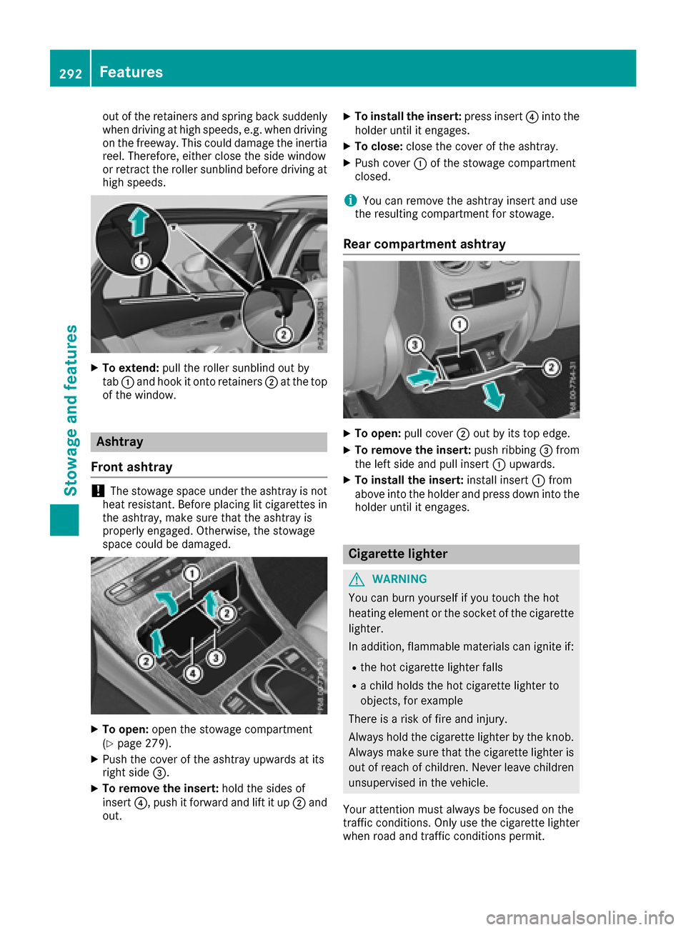
XTo extend:pull the roller sunblind out by
tab :and hook it onto retainers ;at the top
of the window.
Ashtray
Front ashtray
!The stowage space under the ashtray is not
heat resistant. Before placing lit cigarettes in the ashtray, make sure that the ashtray is
properly engaged. Otherwise, the stowage
space could be damaged.
XTo open: open the stowage compartment
(Ypage 279).
XPush the cover of the ashtray upwards at its
right side =.
XTo remove the insert: hold the sides of
insert ?, push it forward and lift it up ;and
out.
XTo install the insert: press insert?into the
holder until it engages.
XTo close: close the cover of the ashtray.
XPush cover :of the stowage compartment
closed.
iYou can remove the ashtray insert and use
the resulting compartment for stowage.
Rear compartment ashtray
XTo open: pull cover ;out by its top edge.
XTo remove the insert: push ribbing=from
the left side and pull insert :upwards.
XTo install the insert: install insert:from
above into the holder and press down into the
holder until it engages.
Cigarette lighter
GWARNING
You can burn yourself if you touch the hot
heating element or the socket of the cigarette lighter.
In addition, flammable materials can ignite if:
Rthe hot cigarette lighter falls
Ra child holds the hot cigarette lighter to
objects, for example
There is a risk of fire and injury.
Always hold the cigarette lighter by the knob.
Always make sure that the cigarette lighter is
out of reach of children. Never leave children
unsupervised in the vehicle.
Your attention must always be focused on the
traffic conditions. Only use the cigarette lighter when road and traffic conditions permit.
292Features
Stowage and features
Page 295 of 374
Cigarette lighter (example)
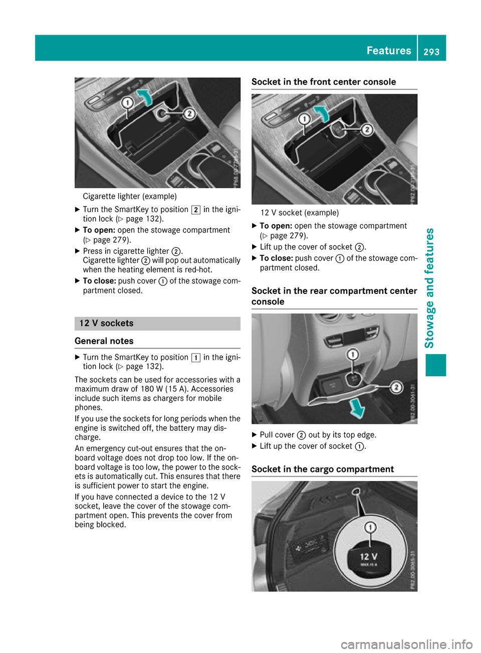
XTurn theSmartKey to position 2inthe igni-
tion lock (Ypage 132).
XTo open: open the stowage compartment
(Ypage 279).
XPress incigarette lighter ;.
Cigarette lighter ;will pop out automatically
when the heating element isred-hot.
XTo close: push cover :of the stowage com-
partment closed.
12 V sockets
General notes
XTurn the SmartKey to position 1inthe igni-
tion lock (Ypage 132).
The sockets can beused for accessories with a
maximum draw of 180 W (15 A). Accessories
inc lude such items as chargers for mob ile
phones.
If you use the sockets for long periods when the
engine is switched off, the battery may dis-
charge.
An emergency cut-out ensures that the on-
board voltage does not drop too low. Ifthe on-
board voltage is too low,the power to the sock-
ets isautomatically cut. This ensures that there
is suff icient power to start the engine.
If you have connected a device to the 12 V
socket, leave the cover of the stowage com-
partment open. This prevents the cover from
bein gbloc ked.
Socket in the front center console
12 V socket (example)
XTo open: open the stowage compartment
(Ypage 279).
XLift up the cover of socket ;.
XTo close:push cover :of the stowage com-
partment closed.
Socket in the rear compartment center
console
XPull cover ;out by its top edge.
XLift up the cover of socket :.
Socket in the cargo compartment
Features293
Stowage and features
Z
Page 296 of 374
XLift up the cover of socket:.
115 V socket
Important safety notes
GDANGER
When a suitable device is connected, the
115 V power socket will be carrying a high
voltage. You could receive an electric shock if the connector cable or the 115 V power
socket is pulled out of the trim or is damaged
or wet. There is a risk of fatal injury.
RUse only connector cables that are dry and
free of damage.
RWhen the ignition is off, make sure that the
115 V power socket is dry.
RHave the 115 V power socket checked or
replaced immediately at a qualified speci-
alized workshop if it is damaged or has been
pulled out of the trim.
RNever plug the connector cable into a 115 V
power socket that is damaged or has been
pulled out of the trim.
GDANGER
If you reach into the power socket or plug
inappropriate devices into the power socket,
you could receive an electric shock. There is a
risk of fatal injury.
Only connect appropriate devices to the
power socket.
!Note that work and repairs on the 115 V
power socket should only be carried out by
qualified specialist personnel.
General notes
The 115 V power socket provides an alternating
voltage of 115 V so that small electronic devices can be connected. These devices, such as
games consoles, chargers and laptops, must not
consume more than a maximum of 150 watts
altogether.
Requirements for operation of these devices:
Rthe electronic device that you connect has a
suitable connector and conforms to stand-
ards specific to the country you are in.
Rthe plug of the electronic device is plugged
correctly into 115 V power socket.
Rthe maximum wattage of the device to be
connected must not exceed 150 watts.
Rthe on-board power supply is within a permis-sible voltage range.
Rthe 12 V sockets in the rear compartment and
the cargo compartment are operational.
Using the 115 V power socket
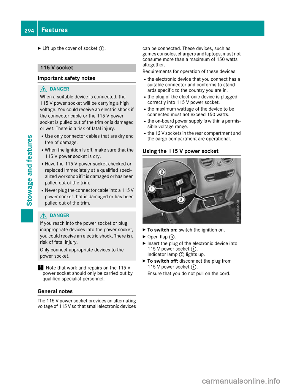
XTo switch on: switch the ignition on.
XOpen flap=.
XInsert the plug of the electronic device into
115 V power socket :.
Indicator lamp ;lights up.
XTo switch off: disconnect the plug from
115 V power socket :.
Ensure that you do not pull on the cord.
294Features
Stowage and features
Page 321 of 374
Where will I find...?
Reflective safety jacket
Removing/replacing the reflective
safety jacket
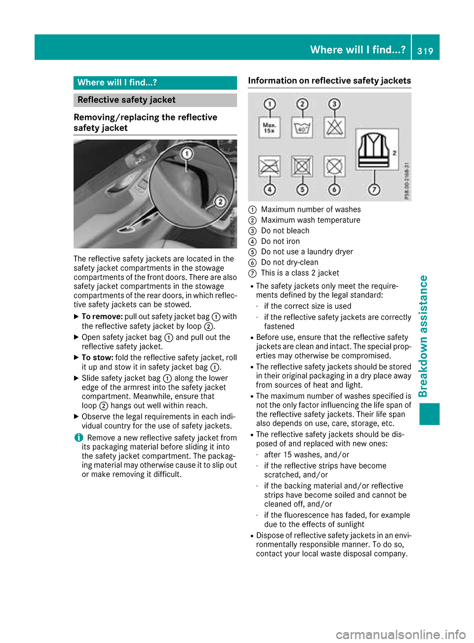
The reflective safety jackets are located in the
safety jacket compartments in the stowage
compartments of the front doors. There are also
safety jacket compartments in the stowage
compartments of the rear doors, in which reflec-
tive safety jackets can be stowed.
XTo remove: pull out safety jacket bag :with
the reflective safety jacket by loop ;.
XOpen safety jacket bag:and pull out the
reflective safety jacket.
XTo stow: fold the reflective safety jacket, roll
it up and stow it in safety jacket bag :.
XSlide safety jacket bag:along the lower
edge of the armrest into the safety jacket
compartment. Meanwhile, ensure that
loop ;hangs out well within reach.
XObserve the legal requirements in each indi-
vidual country for the use of safety jackets.
iRemove a new reflective safety jacket from
its packaging material before sliding it into
the safety jacket compartment. The packag-
ing material may otherwise cause it to slip out
or make removing it difficult.
Information on reflective safety jackets
:Maximum number of washes
;Maximum wash temperature
=Do not bleach
?Do not iron
ADo not use a laundry dryer
BDo not dry-clean
CThis is a class 2 jacket
RThe safety jackets only meet the require-
ments defined by the legal standard:
-if the correct size is used
-if the reflective safety jackets are correctly
fastened
RBefore use, ensure that the reflective safety
jackets are clean and intact. The special prop-
erties may otherwise be compromised.
RThe reflective safety jackets should be stored
in their original packaging in a dry place away
from sources of heat and light.
RThe maximum number of washes specified is not the only factor influencing the life span of
the reflective safety jackets. Their life span
also depends on use, care, storage, etc.
RThe reflective safety jackets should be dis-
posed of and replaced with new ones:
-after 15 washes, and/or
-if the reflective strips have become
scratched, and/or
-if the backing material and/or reflective
strips have become soiled and cannot be
cleaned off, and/or
-if the fluorescence has faded, for example
due to the effects of sunlight
RDispose of reflective safety jackets in an envi-
ronmentally responsible manner. To do so,
contact your local waste disposal company.
Where will I find...?319
Breakdown assistance
Page 322 of 374
Towing eye
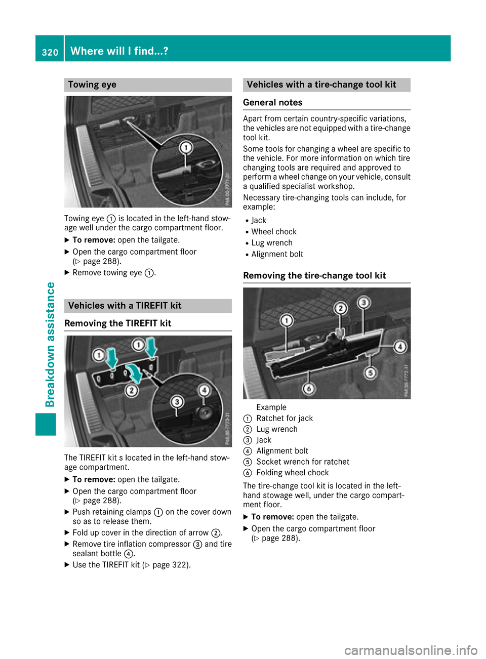
Towing eye:is located in the left-hand stow-
age well under the cargo compartment floor.
XTo remove: open the tailgate.
XOpen the cargo compartment floor
(Ypage 288).
XRemove towing eye :.
Vehicles with a TIREFIT kit
Removing the TIREFIT kit
The TIREFIT kit s located in the left-hand stow-
age compartment.
XTo remove: open the tailgate.
XOpen the cargo compartment floor
(Ypage 288).
XPush retaining clamps :on the cover down
so as to release them.
XFold up cover in the direction of arrow ;.
XRemove tire inflation compressor=and tire
sealant bottle ?.
XUse the TIREFIT kit (Ypage 322).
Vehicles with a tire-change tool kit
General notes
Apart from certain country-specific variations,
the vehicles are not equipped with a tire-change
tool kit.
Some tools for changing a wheel are specific to the vehicle. For more information on which tire
changing tools are required and approved to
perform a wheel change on your vehicle, consult
a qualified specialist workshop.
Necessary tire-changing tools can include, for
example:
RJack
RWheel chock
RLug wrench
RAlignment bolt
Removing the tire-change tool kit
Example
:Ratchet for jack
;Lug wrench
=Jack
?Alignment bolt
ASocket wrench for ratchet
BFolding wheel chock
The tire-change tool kit is located in the left-
hand stowage well, under the cargo compart-
ment floor.
XTo remove: open the tailgate.
XOpen the cargo compartment floor
(Ypage 288).
320WherewillIfind ...?
Breakdown assis tance