2017 MERCEDES-BENZ GLC SUV height
[x] Cancel search: heightPage 224 of 374

Head-up display submenu
Selecting other displays
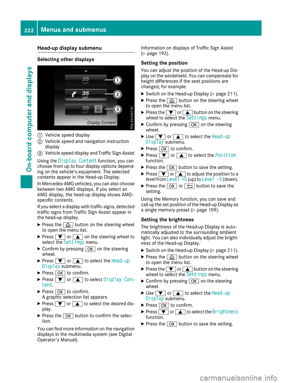
:Vehicle speed display
;Vehicle speed and navigation instruction
display
=Vehicle speed display and Traffic Sign Assist
Using the Display Content
function, you can
choose from up to four display options depend-
ing on the vehicle's equipment. The selected
contents appear in the Head-up Display.
In Mercedes-AMG vehicles, you can also choose
between two AMG displays. If you select an
AMG display, the head-up display shows AMG-
specific contents.
If you select a display with traffic signs, detected
traffic signs from Traffic Sign Assist appear in
the head-up display.
XPress the òbutton on the steering wheel
to open the menu list.
XPress :or9 on the steering wheel to
select the Settingsmenu.
XConfirm by pressing aon the steering
wheel.
XPress :or9 to select the Head-upDisplaysubmenu.
XPressato confirm.
XPress :or9 to select Display Con‐tent.
XPressato confirm.
A graphic selection list appears.
XPress :or9 to select the desired dis-
play.
XPress the abutton to confirm the selec-
tion.
You can find more information on the navigation
displays in the multimedia system (see Digital
Operator's Manual). Information on displays of Traffic Sign Assist
(
Ypage 192).
Setting the position
You can adjust the position of the Head-up Dis-
play on the windshield. You can compensate for
height differences if the seat positions are
changed, for example.
XSwitch on the Head-up Display (Ypage 211).
XPress the
òbutton on the steering wheel
to open the menu list.
XPress the :or9 button on the steering
wheel to select the Settingsmenu.
XConfirm by pressing aon the steering
wheel.
XUse : or9 to select the Head-upDisplaysubmenu.
XPressato confirm.
XPress :or9 to select the Positionfunction.
XPress theabutton to save the setting.
XPress :or9 to adjust the position to a
level from Level+5(up) toLevel-5(down).
XPress the aor% button to save the
setting.
Using the Memory function, you can save and
call up the set position of the Head-up Display as
a single memory preset (
Ypage 109).
Setting the brightness
The brightness of the Head-up Display is auto-
matically adjusted to the surrounding ambient
light. You can also individually adjust the bright-
ness of the Head-up Display.
XSwitch on the Head-up Display (Ypage 211).
XPress the òbutton on the steering wheel
to open the menu list.
XPress the :or9 button on the steering
wheel to select the Settingsmenu.
XConfirm by pressing aon the steering
wheel.
XUse : or9 to select the Head-upDisplaysubmenu.
XPressato confirm.
XPress :or9 to select the Brightnessfunction.
XPress theabutton to save the setting.
222Menus and submenus
On-board computer and displays
Page 309 of 374

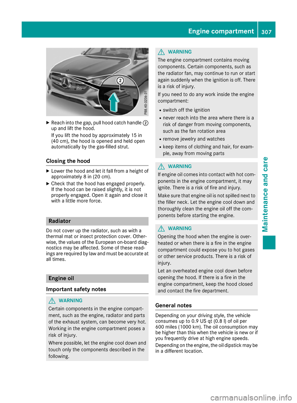
XReachint oth egap, pull hoo dcatch handle ;
up and lift th ehood.
If you lift th ehoo dby approximately 15 in
(40 cm), th ehoo dis opened and held open
automatically by th egas-filled strut .
Closing the hood
XLowerth ehoo dand let it fall from aheight of
approximately 8in (20 cm).
XChec kthat th ehoo dhas engage dproperly.
If th ehoo dcan be raised slightly, it is no t
properly engaged. Open it again and close it
wit h a littlemor eforce .
Radiator
Do no tcover up th eradiator, suc has wit h a
thermal mat or insec tprotection cover .Other -
wise, th evalue sof th eEuropean on-board diag-
nostics may be affected. Some of these read -
ing sare require dby law and mus tbe accurat eat
all times .
Engine oil
Important safety notes
GWARNIN G
Certain component sin th eengin ecompart-
ment, suc has th eengine, radiato rand part s
of th eexhaust system, can become ver yhot .
Workin gin th eengin ecompartmen tposes a
ris kof injury.
Wher epossible, let th eengin ecool down and
touch only th ecomponent sdescribe din th e
following.
GWARNIN G
The engin ecompartmen tcontain smoving
components. Certain components, suc has
th eradiato rfan ,may continu eto run or start
again suddenly when th eignition is off .There
is aris kof injury.
If you need to do any wor kinside th eengin e
compartment:
Rswitch off th eignition
Rnever reac hint oth earea wher ethere is a
ris kof danger from moving components,
suc has th efan rotation area
Rremove jewelr yand watches
Rkeep items of clothing and hair ,for exam-
ple, away from moving part s
GWARNING
If engin eoil comes int ocontact wit hhot com-
ponents in th eengin ecompartment, it may
ignite. There is aris kof fir eand injury.
Mak esur ethat engin eoil is no tspilled next to
th efiller neck .Let th eengin ecool down and
thoroughly clean th eengin eoil off th ecom-
ponents before starting th eengine.
GWARNIN G
Opening th ehoo dwhen th eengin eis over-
heated or when there is afir ein th eengin e
compartmen tcould expos eyou to hot gase s
or other servic eproducts .There is aris kof
injury.
Let an overheate dengin ecool down before
opening th ehood. If there is afir ein th e
engin ecompartment, keep th ehoo dclosed
and contact th efir edepartment.
General notes
Dependin gon your driving style, th evehicl e
consumes up to 0. 9US qt (0. 8l) of oil per
60 0mile s(1000 km). The oil consumption may
be higher than this when the vehicle is new or if
you frequently drive at high engine speeds.
Depending on the engine, the oil dipstick may be
in a different location.
Engine compartment307
Maintenance and care
Z
Page 353 of 374

Tire labeling
Overview
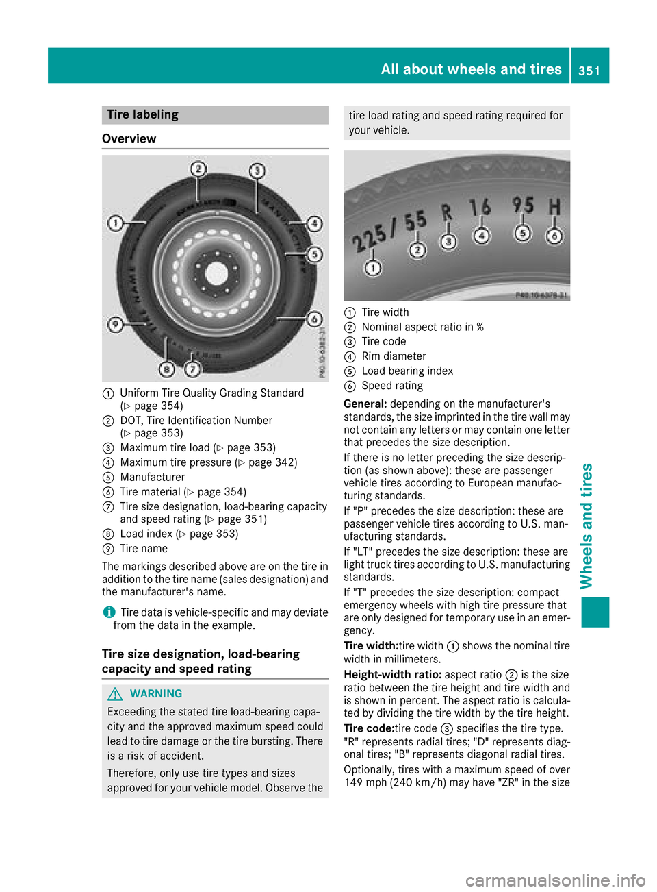
:Uniform Tire Quality Grading Standard
(Ypage 354)
;DOT, Tire Identification Number
(Ypage 353)
=Maximum tire load (Ypage 353)
?Maximum tire pressure (Ypage 342)
AManufacturer
BTire material (Ypage 354)
CTire size designation, load-bearing capacity
and speed rating (Ypage 351)
DLoad index (Ypage 353)
ETire name
The markings described above are on the tire in
addition to the tire name (sales designation) and
the manufacturer's name.
iTire data is vehicle-specific and may deviate
from the data in the example.
Tire size designation, load-bearing
capacity and speed rating
GWARNING
Exceeding the stated tire load-bearing capa-
city and the approved maximum speed could
lead to tire damage or the tire bursting. There is a risk of accident.
Therefore, only use tire types and sizes
approved for your vehicle model. Observe the
tire load rating and speed rating required for
your vehicle.
:Tire width
;Nominal aspect ratio in %
=Tire code
?Rim diameter
ALoad bearing index
BSpeed rating
General: depending on the manufacturer's
standards, the size imprinted in the tire wall may
not contain any letters or may contain one letter
that precedes the size description.
If there is no letter preceding the size descrip-
tion (as shown above): these are passenger
vehicle tires according to European manufac-
turing standards.
If "P" precedes the size description: these are
passenger vehicle tires according to U.S. man-
ufacturing standards.
If "LT" precedes the size description: these are
light truck tires according to U.S. manufacturing
standards.
If "T" precedes the size description: compact
emergency wheels with high tire pressure that
are only designed for temporary use in an emer-
gency.
Tire width: tire width:shows the nominal tire
width in millimeters.
Height-width ratio: aspect ratio;is the size
ratio between the tire height and tire width and
is shown in percent. The aspect ratio is calcula-
ted by dividing the tire width by the tire height.
Tire code:tire code =specifies the tire type.
"R" represents radial tires; "D" represents diag-
onal tires
; "B" represents diagonal radial tires.
Optionally, tires with a maximum speed of over
149 mph (240 km/h) may have "ZR" in the size
All about wheels an d tires351
Wheels and tires
Z
Page 357 of 374

Speed rating
The speed rating is part of the tire identification.It specifies the speed range for which the tire is
approved.
GVW (Gross Vehicle Weight)
The gross vehicle weight includes the weight of the vehicle including fuel, tools, the spare wheel,
accessories installed, occupants, luggage and
the drawbar noseweight, if applicable. The gross
vehicle weight must not exceed the gross vehi-
cle weight rating GVWR as specified on the vehi- cle identification plate on the B-pillar on the
driver's side.
GVWR (Gross Vehicle Weight Rating)
The GVWR is the maximum permissible gross
weight of a fully loaded vehicle (the weight of the
vehicle including all accessories, occupants,
fuel, luggage and the drawbar noseweight, if
applicable). The gross vehicle weight rating is
specified on the vehicle identification plate on
the B-pillar on the driver's side.
Maximum loaded vehicle weight
The maximum weight is the sum of:
Rthe curb weight of the vehicle
Rthe weight of the accessories
Rthe load limit
Rthe weight of the factory installed optional
equipment
Kilopascal (kPa)
Metric unit for tire pressure. 6.9 kPa corre-
sponds to 1 psi. Another unit for tire pressure is
bar. 100 kilopascals (kPa) are the equivalent of
1 bar.
Load index
In addition to the load-bearing index, the load
index may also be imprinted on the sidewall of
the tire. This specifies the load-bearing capacity
more precisely.
Curb weight
The weight of a vehicle with standard equipment
including the maximum capacity of fuel, oil and
coolant. It also includes the air-conditioning sys-
tem and optional equipment if these are instal-
led in the vehicle, but does not include passen-
gers or luggage.
Maximum load rating
The maximum tire load is the maximum permis-
sible weight in kilograms or lbs for which a tire is
approved.
Maximum permissible tire pressure
Maximum permissible tire pressure for one tire.
Maximum load on one tire
Maximum load on one tire. This is calculated by
dividing the maximum axle load of one axle by
two.
PSI (pounds per square inch)
A standard unit of measure for tire pressure.
Aspect ratio
Relationship between tire height and tire width
in percent.
Tire pressure
This is pressure inside the tire applying an out-
ward force to each square inch of the tire's sur-
face. The tire pressure is specified in pounds per
square inch (psi), in kilopascal (kPa) or in bar.
The tire pressure should only be corrected when the tires are cold.
Cold tire pressure
The tires are cold:
Rif the vehicle has been parked with the tires
out of direct sunlight for at least three hours
and
Rif the vehicle has not been driven further than
1 mile (1.6 km)
Tread
The part of the tire that comes into contact with
the road.
Bead
The tire bead ensures that the tire sits securely
on the wheel. There are several steel wires in the
bead to prevent the tire from coming loose from
the wheel rim.
Sidewall
The part of the tire between the tread and the
bead.
All about wheels and tires355
Wheels and tires
Z
Page 360 of 374

must be positioned vertically, directly under
the jacking point of the vehicle.
!Only position the jack at the appropriate
jacking point of the vehicle. Otherwise, you
could damage the vehicle.
Observe the following when raising the vehi-
cle:
RTo raise the vehicle, only use the vehicle-spe-
cific jack that has been tested and approved
by Mercedes-Benz. If used incorrectly, the
jack could tip over with the vehicle raised.
RThe jack is designed only to raise and hold the
vehicle for a short time while a wheel is being
changed. It must not be used for performing
maintenance work under the vehicle.
RAvoid changing the wheel on uphill and down-
hill slopes.
RBefore raising the vehicle, secure it from roll-
ing away by applying the parking brake and
inserting wheel chocks. Do not disengage the
parking brake while the vehicle is raised.
RThe jack must be placed on a firm, flat and
non-slip surface. On a loose surface, a large,
flat, load-bearing underlay must be used. On a
slippery surface, a non-slip underlay must be
used, e.g. rubber mats.
RDo not use wooden blocks or similar objects
as a jack underlay. Otherwise, the jack will not
be able to achieve its load-bearing capacity
due to the restricted height.
RMake sure that the distance between the
underside of the tires and the ground does not
exceed 1.2 in (3 cm).
RDo not place your hands or feet under the
raised vehicle.
RDo not lie under the vehicle.
RDo not start the engine when the vehicle is
raised.
RNever open or close a door or the tailgate
when the vehicle is raised.
RMake sure that no persons are present in the
vehicle when the vehicle is raised.
XUsing lug wrench :, loosen the bolts on the
wheel you wish to change by about one full
turn. Do not unscrew the bolts completely.
The jacking points are located just behind the
front wheel housings and just in front of the rear
wheel housings (arrows).
XTake the ratchet wrench out of the tire-chang-
ing tool kit and place it on the hexagon nut of the jack so that the letters AUFare visible.
XPosition jack =at jacking point ;.
358Changing a wheel
Wheels and tires
Page 372 of 374

!Only the refrigerant R‑134a and the PAG oil
approved by Mercedes-Benz may be used.
The approved PAG oil may not be mixed with
any other PAG oil that is not approved for
R-134a refrigerant. Otherwise, the climate
control system may be damaged.
Service work, such as refilling with refrigerant or
replacing component parts, may only be carried
out by a qualified specialist workshop. All appli- cable regulations, as well as SAE standard J639,
must be adhered to.
Always have work on the climate control system
carried out at a qualified specialist workshop.
Refrigerant instruction label
Example: refrigerant instruction label
:Warning symbol
;Refrigerant filling capacity
=Applicable standards
?PAG oil part number
AType of refrigerant
Warning symbol :advises you about:
RPossible dangers
RHaving service work carried out at a qualified
specialist workshop
Filling capacities
All models
Refrigerant22.2 ± 0.4 oz
(630 ± 10 g)
PAG oil2.8 oz(80 g)
Vehicle data
General notes
Please note that for the specified vehicle data:
Rthe heights specified may vary as a result of:
-tires
-load
-condition of the suspension
-optional equipment
Roptional equipment reduces the maximum
payload.
Observe the information relating to level con-
trol:
RAIR BODY CONTROL (Ypage 173)
Dimensions and weights
Model:
Opening height
;
Maximum
headroom
Mercedes-
AMG GLC 43
4MATIC82.9 in
(2106 mm)75.6 in
(1920 mm)
All other mod-
els84.5 in
(2146 mm)78.4 in
(1992 mm)
Mercedes-AMG
GLC 43 4MATIC
Vehicle length183.5 in (4661 mm)
Vehicle width
including exterior
mirrors82.5 in (2096 mm)
Vehicle height64.1 in (1629 mm)
370Vehicle data
Technical data
Page 373 of 374

Mercedes-AMG
GLC 43 4MATIC
Wheelbase113.1 in (2873 mm)
Turning circle39.7 ft (12.10m)
Maximum roof load165 lb (75 kg)
Maximum trunk
load
All other models
Vehicle length183.3 in (4656 mm)
Vehicle width
including exterior
mirrors82.5 in (2096 mm)
Vehicle height65.5 in (1664 mm)
Wheelbase113.1 in (2873 mm)
Turning circle38.7 ft (11.80m)
Maximum roof load165 lb (75 kg)
Maximum trunk
load220 lb (100 kg)
Trailer tow hitch
Trailer loads
Permissible trailer load, braked (at a
minimum gradient-climbing capability
of 12% from a standstill)
Model
All models3501 lb (1588 kg)
Maximum drawbar noseweight
!Use a drawbar noseweight as close as pos-
sible to the maximum permissible nose-
weight. Do not use a noseweight of less than
50 kg, otherwise the trailer may come loose.
Note that the payload and the rear axle load
are reduced by the actual payload.
Towing a trailer is not possible with all models.
Further information (
Ypage 203).
The drawbar load reduces the permissible over-
all load and rear axle load. The drawbar load acts from above onto the ball
head on the trailer tow hitch.
The trailer drawbar noseweight is not included in
the towing weight.
ModelPermissible nose-
weight
All models280 lbs (127 kg)
The actual noseweight may not be higher than
the value which is given. The value can be found
on the trailer tow hitch or trailer identification
plates. The lowest weight applies.
The maximum permissible trailer drawbar nose-
weight is the maximum weight with which the
trailer drawbar can be loaded. The permissible
trailer drawbar noseweight is the limit for
Mercedes-Benz-approved trailer couplings.
Gross rear axle weight rating when
towing a trailer
Missing values were not available at time of
going to print.
ModelGross axle weight rating
GLC 300 d 4MATIC
Mercedes-AMG
GLC 43 4MATIC2822 lbs (1280 kg)
All other models2755 lbs (1250 kg)
Ball position of the ball coupling
Trailer tow hitch371
Technical data
Z