2017 MERCEDES-BENZ GLC SUV rear view mirror
[x] Cancel search: rear view mirrorPage 109 of 374
For this reason, always make sure of the
actual distance from the road users traveling
behind by glancing over your shoulder.
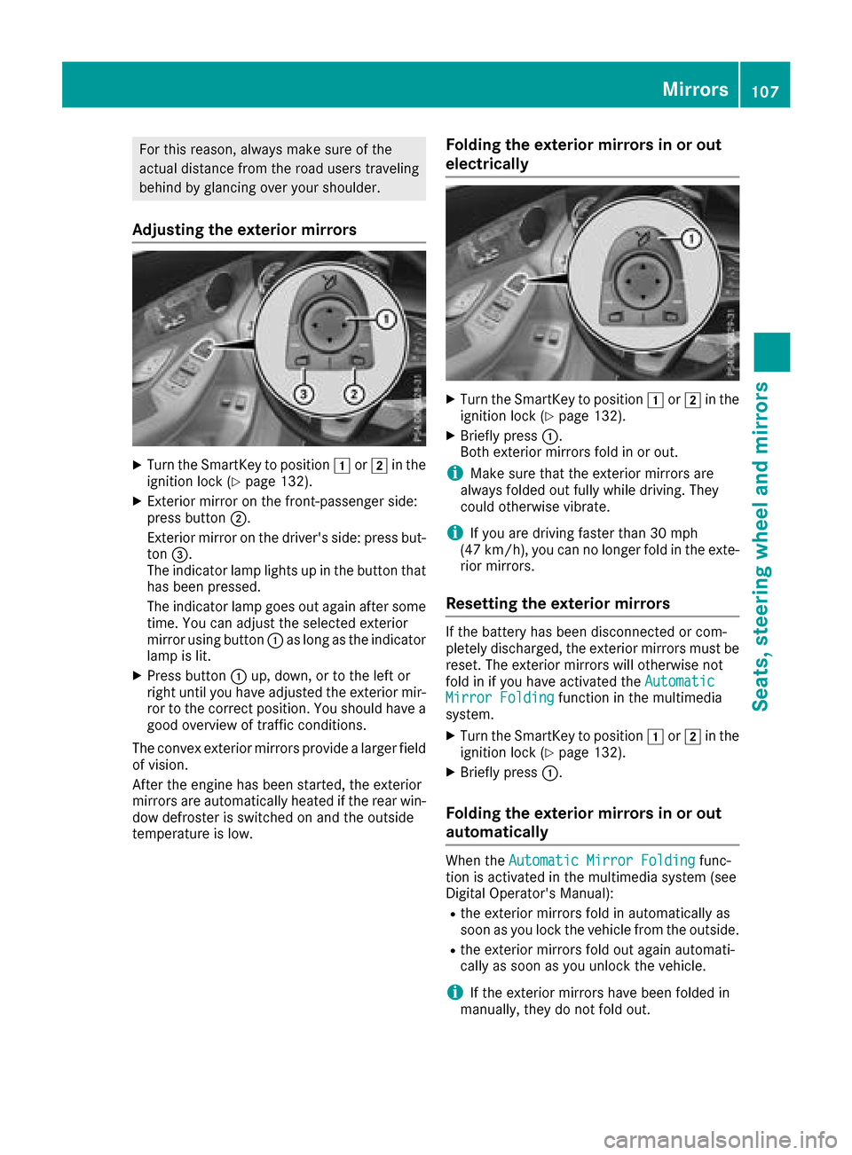
Adjusting the exterior mirrors
XTurn the SmartKey to position1or2 in the
ignition lock (Ypage 132).
XExterior mirror on the front-passenger side:
press button ;.
Exterior mirror on the driver's side: press but-
ton =.
The indicator lamp lights up in the button that
has been pressed.
The indicator lamp goes out again after some
time. You can adjust the selected exterior
mirror using button :as long as the indicator
lamp is lit.
XPress button :up, down, or to the left or
right until you have adjusted the exterior mir-
ror to the correct position. You should have a
good overview of traffic conditions.
The convex exterior mirrors provide a larger field of vision.
After the engine has been started, the exterior
mirrors are automatically heated if the rear win-
dow defroster is switched on and the outside
temperature is low.
Folding the exterior mirrors in or out
electrically
XTurn the SmartKey to position 1or2 in the
ignition lock (Ypage 132).
XBriefly press :.
Both exterior mirrors fold in or out.
iMake sure that the exterior mirrors are
always folded out fully while driving. They
could otherwise vibrate.
iIf you are driving faster than 30 mph
(47 km/h), you can no longer fold in the exte-
rior mirrors.
Resetting the exterior mirrors
If the battery has been disconnected or com-
pletely discharged, the exterior mirrors must be
reset. The exterior mirrors will otherwise not
fold in if you have activated the Automatic
Mirror Foldingfunction in the multimedia
system.
XTurn the SmartKey to position 1or2 in the
ignition lock (Ypage 132).
XBriefly press :.
Folding the exterior mirrors in or out
automatically
When theAutomatic Mirror Foldingfunc-
tion is activated in the multimedia system (see
Digital Operator's Manual):
Rthe exterior mirrors fold in automatically as
soon as you lock the vehicle from the outside.
Rthe exterior mirrors fold out again automati-
cally as soon as you unlock the vehicle.
iIf the exterior mirrors have been folded in
manually, they do not fold out.
Mirrors107
Seats, steering wheel and mirrors
Z
Page 110 of 374
Exterior mirror pushed out of position
If an exterior mirror has been pushed out of
position, proceed as follows:
XVehicles without electrically folding exte-
rior mirrors:manually move the exterior mir-
ror into the correct position.
XVehicles with electrically folding exterior
mirrors: press and hold button :until you
hear a click and then the mirror engaging in
position (
Ypage 107).
The mirror housing is engaged again and you
can adjust the exterior mirrors as usual
(
Ypage 107).
If an exterior mirror has been pushed out of
position, proceed as follows:
XPress and hold button :until you hear a click
and the mirror engages audibly into position
(
Ypage 107).
The mirror housing is engaged again and you
can adjust the exterior mirrors as usual
(
Ypage 107).
Automatic anti-glare mirrors
GWARNING
Electrolyte may escape if the glass in an auto-
matic anti-glare mirror breaks. The electrolyte
is harmful and causes irritation. It must not
come into contact with your skin, eyes, res-
piratory organs or clothing or be swallowed.
There is a risk of injury.
If you come into contact with the electrolyte,
observe the following:
RRinse off the electrolyte from your skin
immediately with water.
RImmediately rinse the electrolyte out of
your eyes thoroughly with clean water.
RIf the electrolyte is swallowed, immediately
rinse your mouth out thoroughly. Do not
induce vomiting.
RIf electrolyte comes into contact with your
skin or hair or is swallowed, seek medical
attention immediately.
RImmediately change out of clothing which
has come into contact with electrolyte.
RIf an allergic reaction occurs, seek medical
attention immediately.
The exterior mirror on the driver's side and the
rear-view mirror automatically go into anti-glare mode if:
Rthe ignition is switched on
Rincident light from headlamps strikes the sen-
sor in the rear-view mirror
The mirrors do not go into anti-glare mode if
reverse gear is engaged or if the interior lighting
is switched on.
Parking position for the exterior mir-
ror on the front-passenger side
Storing the parking position
You can set the front-passenger side exterior
mirror such that you can see the rear wheel on
that side as soon as you engage reverse gear.
You can store this position.
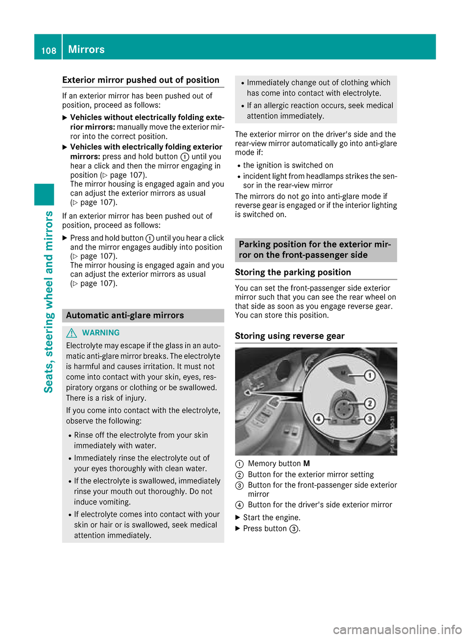
Storing using reverse gear
:Memory button M
;Button for the exterior mirror setting
=Button for the front-passenger side exterior
mirror
?Button for the driver's side exterior mirror
XStart the engine.
XPress button=.
108Mirrors
Seats, steering wheel and mirrors
Page 184 of 374
Surroundingsmessage appears on the mul-
tifunction display.
iYou will achieve the best results by waiting
for the steering procedure to complete before
pulling away.
If you back up after activation, the steering
wheel is moved to the straight-ahead posi-
tion.
XDrive forward and back up as prompted by the
PARKTRONIC warning displays, several times
if necessary.
Once you have exited the parking space com-
pletely, the steering wheel is moved to the
straight-ahead position. You hear a tone and the Park
AssistSwitchedOffmessage appears
on the multifunction display. You will then have
to steer and merge into traffic on your own.
PARKTRONIC is still available. You can take over
the steering before the vehicle has exited the
parking space completely. This is useful if you
recognize that it is already possible to pull out of
the parking space.
Canceling Active Parking Assist
XStop the movement of the multifunction
steering wheel or steer yourself.
Active Parking Assist will be canceled at once.
The Park Assist Canceled
message
appears in the multifunction display.
or
XPress the PARKTRONIC button (Ypage 177).
PARKTRONIC is switched off and Active Park-
ing Assist is immediately canceled. The Park
Assist Canceledmessage appears in the
multifunction display.
Active Parking Assist is canceled automatically
if:
Rthe electric parking brake is engaged
Rtransmission position jis selected
Rparking using Active Parking Assist is no lon-
ger possible
Ryou are driving faster than 6 mph (10 km/h)
Ra wheel spins, ESP®intervenes or fails. In
such cases the ÷warning lamp lights up in
the instrument cluster
A warning tone sounds. The parking symbol dis-
appears and the multifunction display shows the
Park Assist Canceled
message.
When Active Parking Assist is canceled, you
must steer and brake again yourself. If a system malfunction occurs, the vehicle is
braked to a standstill. To drive on, depress the
accelerator again.
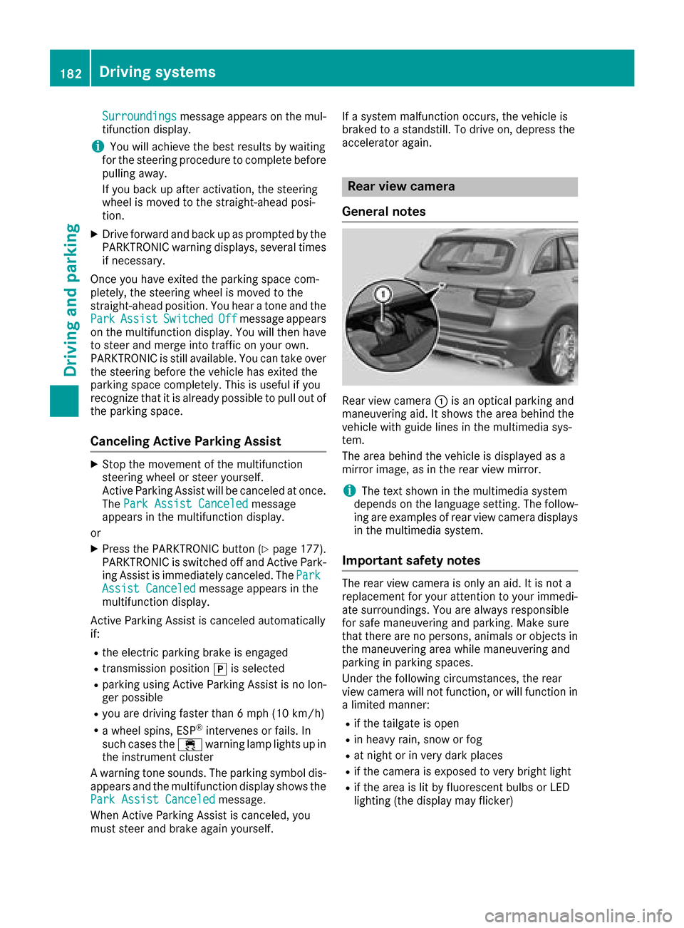
Rear view camera
General notes
Rear view camera :is an optical parking and
maneuvering aid. It shows the area behind the
vehicle with guide lines in the multimedia sys-
tem.
The area behind the vehicle is displayed as a
mirror image, as in the rear view mirror.
iThe text shown in the multimedia system
depends on the language setting. The follow-
ing are examples of rear view camera displays
in the multimedia system.
Important safety notes
The rear view camera is only an aid. It is not a
replacement for your attention to your immedi-
ate surroundings. You are always responsible
for safe maneuvering and parking. Make sure
that there are no persons, animals or objects in
the maneuvering area while maneuvering and
parking in parking spaces.
Under the following circumstances, the rear
view camera will not function, or will function in
a limited manner:
Rif the tailgate is open
Rin heavy rain, snow or fog
Rat night or in very dark places
Rif the camera is exposed to very bright light
Rif the area is lit by fluorescent bulbs or LED
lighting (the display may flicker)
182Driving systems
Driving and parking
Page 189 of 374
360° camera
General notes
The 360° camera is a system consisting of four
cameras.
The system processes images from the follow-
ing cameras:
RRear view camera
RFront camera
RTwo side cameras in the exterior mirrors
The cameras cover the immediate surroundings
of the vehicle. The system supports you, for
example when parking or if vision is restricted at
an exit.
You can show images from the 360° camera in
full-screen mode or in seven different split-
screen views on the multimedia system. A split- screen view also includes a top view of the vehi-
cle. This view is calculated from the data sup-
plied by the installed cameras (virtual camera).
The seven split-screen views are:
RTop view and picture from the rear view cam-
era (130° viewing angle)
RTop view and image from the front camera
(130° viewing angle without displaying the
maximum steering wheel angle)
RTop view and enlarged rear view
RTop view and enlarged front view
RTop view and trailer view (vehicles with trailer
tow hitch)
RTop view and images from the rear-facing side
cameras (rear wheel view)
RTop view and images from the forward-facing
side cameras (front wheel view)
When the function is active and you shift the
transmission from hork toi, the guide
lines are hidden in the multimedia system.
When you change between transmission posi-
tions hand k, you see the previously selec-
ted front or rear view.
Distances measured by PARKTRONIC will also
be optically displayed:
Rin split screen view as red or yellow brackets
around the vehicle icon in the top view, or
Rat the bottom right as red or yellow brackets
around the vehicle symbol in full-screen mode
The line thickness and color of the brackets
show how far the vehicle is from an object.
Ryellow brackets with thin lines: PARKTRONIC
is active
Ryellow brackets with normal lines: an object is present in close range of the vehicle
Rred line: an object is present in the immediate
close range of the vehicle
Important safety notes
The 360°camera is only an aid and may show a
distorted view of obstacles, show them incor-
rectly or not at all. The 360°camera is not a
substitute for attentive driving.
You are always responsible for safe maneuver-
ing and parking. Make sure that there are no
persons, animals or objects in the maneuvering
area while maneuvering and parking in parking
spaces.
You are always responsible for safety, and must
always pay attention to your surroundings when
parking and maneuvering. This applies to the
areas behind, in front of and beside the vehicle. You could otherwise endanger yourself and oth-
ers.
The 360° camera will not function or will func-
tion in a limited manner:
Rif the doors are open
Rif the exterior mirrors are folded in
Rif the tailgate is open
Rin heavy rain, snow or fog
Rat night or in very dark places
Rif the cameras are exposed to very bright light
Rif the area is lit by fluorescent bulbs or LED
lighting (the display may flicker)
Rif the camera lenses fog up, e.g. when driving
into a heated garage in winter, causing a rapid
change in temperature
Rif the camera lenses are dirty or covered
Rif the vehicle components in which the cam-
eras are installed are damaged. In this case,
have the camera position and setting checked
at a qualified specialist workshop
Do not use the 360° camera in this case. You
can otherwise injure others or cause damage to
objects or the vehicle.
The guide lines in the multimedia system display
show the distances to your vehicle. The distan-
ces only apply to road level.
In trailer mode, the guide lines are shown at the
level of the trailer tow hitch.
Driving systems187
Driving and parking
Z
Page 191 of 374
Rvery close to the exterior mirrors
Rin the transitional areas between the various
cameras in the virtual top view
!Objects not at ground level may appear to
be further away than they actually are, e.g.:
Rthe bumper of a parked vehicle
Rthe drawbar of a trailer
Rthe ball coupling of a trailer tow hitch
Rthe rear section of an HGV
Ra slanted post
Use the guidelines only for orientation.
Approach objects no further than the bottom-
most guideline.
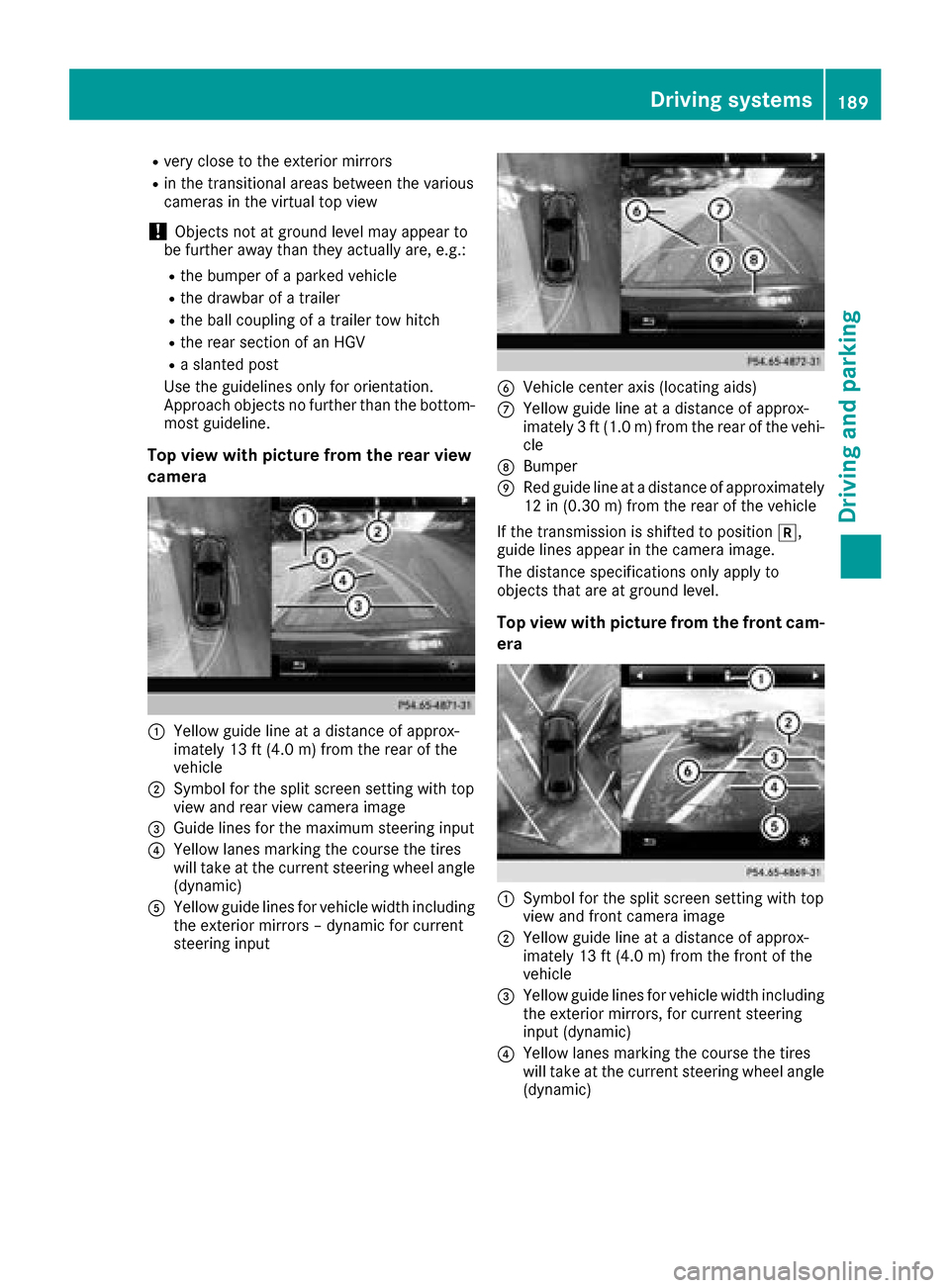
Top view with picture from the rear view
camera
:Yellow guide line at a distance of approx-
imately 13 ft (4.0 m) from the rear of the
vehicle
;Symbol for the split screen setting with top
view and rear view camera image
=Guide lines for the maximum steering input
?Yellow lanes marking the course the tires
will take at the current steering wheel angle
(dynamic)
AYellow guide lines for vehicle width including
the exterior mirrors – dynamic for current
steering input
BVehicle center axis (locating aids)
CYellow guide line at a distance of approx-
imately 3 ft (1.0 m) from the rear of the vehi-
cle
DBumper
ERed guide line at a distance of approximately
12 in (0.30 m) from the rear of the vehicle
If the transmission is shifted to position k,
guide lines appear in the camera image.
The distance specifications only apply to
objects that are at ground level.
Top view with picture from the front cam-
era
:Symbol for the split screen setting with top
view and front camera image
;Yellow guide line at a distance of approx-
imately 13 ft (4.0 m) from the front of the
vehicle
=Yellow guide lines for vehicle width including
the exterior mirrors, for current steering
input (dynamic)
?Yellow lanes marking the course the tires
will take at the current steering wheel angle
(dynamic)
Driving systems189
Driving and parking
Z
Page 192 of 374

ARed guide lineat adistanc eof approximately
12 in (0.30m) from the front of the vehicle
BYellow guide line at a distance of approx-
imately 3 ft (1.0 m) fromthe front of the
vehicle
Top view and enlarged rear view
:Symbol for the split screen setting with top
view and rear view camera image enlarged
;Red guide line at a distance of approximately
12 in (0.30 m)from the rear of the vehicle
This view assists you in estimating the distance
to the vehicle behind you.
iThis setting can also be selected as an
enlarged front view.
Top view with image from the side cam-
eras
:Symbol for the top view and forward-facing
side camera setting
;Yellow guide line for the vehicle width
including the exterior mirrors (right side of
vehicle)
=Yellow guide line for the vehicle width
including the exterior mirrors (left side of
vehicle)
iYou can also select the side camera setting
for the rear-facing view.
"Coupling up a trailer" function
:Vehicle center point on the yellow guide line
at a distance of approximately 3 ft (1.0 m)
from the rear of the vehicle
;Trailer drawbar
=Red guide line at a distance of approximately
12 in (0.30 m) from the rear of the vehicle
XSet the height of trailer drawbar ;so that it
is slightly higher than the ball coupling.
XPosition the vehicle centrally in front of trailer
drawbar ;.
For technical reasons, the ball coupling Bof
the trailer tow hitch on the multimedia system
display is either only partially visible or not visi-
ble at all.
XSelect symbol ?using the controller.
The "Coupling up a trailer" function is selec-
ted. The distance specifications now only
apply to objects that are at the same level as
the ball coupling.
XReverse carefully, making sure that trailer
drawbar locating aid Apoints approximately
in the direction of the trailer drawbar.
190Driving systems
Driving and parking
Page 207 of 374
XSwitch off the engine.
XClose the doors and tailgate.
XCouple up the trailer.
XEstablish the electrical connection between
the vehicle and the trailer.
XCheck that the trailer lighting system is work-
ing.
XPush the combination switch upwards/down-wards and check whether the corresponding
turn signal on the trailer flashes.
A trailer that is connected is recognized only
when the electrical connection is established
correctly and when the lighting system is work-
ing properly. The function of other systems also
depends on this, for example:
RESP®
RPARKTRONIC
RActive Parking Assist
RActive Blind Spot Assist
RActive Lane Keeping Assist
Vehicles with AIR BODY CONTROL: if you couple
up a trailer, the vehicle always remains at high-
way level. Observe the following note when cou-
pling up a trailer:
RUnless highway level has been set manually,
the vehicle is automatically lowered to high-
way level. If a speed of 5 mph (8 km/h) has
been reached, this may be the case.
These restrictions apply to accessories that are
supplied with power via the trailer socket in your
vehicle, e.g. a rear bicycle rack.
Observe the maximum permissible trailer
dimensions (width and length).
Most U.S. states and all Canadian provinces
require by law:
RSafety chains between the towing vehicle and
the trailer. The chains should be cross-wound
under the trailer drawbar. They must be fas-
tened to the vehicle's trailer coupling, not to
the bumper or the axle.
Leave enough play in the chains to make tight
cornering possible.
RA separate brake system for certain types of
trailer.
RSafety switch for braked trailers. Check the
specific legal requirements applicable to your state.
If the trailer becomes detached from the tow-
ing vehicle, the safety feature applies the
trailer brakes.
Towing a trailer
There are several legal requirements for towing
a trailer, e.g. the maximum permissible speed.
Make sure that your car/trailer combination
complies with the local regulations:
Rin your place of residence
Rat your destination
The police and local authorities can provide reli- able information.
To accumulate driving experience and accustom
yourself to the new handling characteristics,
practice the following at a location where there
is no traffic:
RCornering
RStopping
RBacking up
Check the following before the journey:
RTrailer tow hitch
RSafety switch for braked trailers
RSafety chains
RElectrical connections
RLighting system
RWheels and tires
RLoad securing
Adjust the exterior mirrors so that you have a
clear view of the rear section of the trailer.
If the trailer is equipped with electronically con-
trolled brakes, pull away carefully in the car/
trailer combination. Brake manually using the
brake controller and check whether the brakes
function correctly.
Regularly check that the load is secure.
When towing a trailer, your vehicle's handling
characteristics will be different in comparison
with when driving without a trailer.
The vehicle/trailer combination:
Ris heavier
Ris restricted in its acceleration and gradient-
climbing capability
Rhas an increased braking distance
Ris affected more by strong crosswinds
Rdemands more sensitive steering
Rhas a larger turning circle
Avoid sudden steering movements.
Avoid braking abruptly. If possible, brake gently
at first to allow the trailer to run on. Then,
increase the braking force rapidly.
Towing a trailer205
Driving and parking
Z
Page 293 of 374
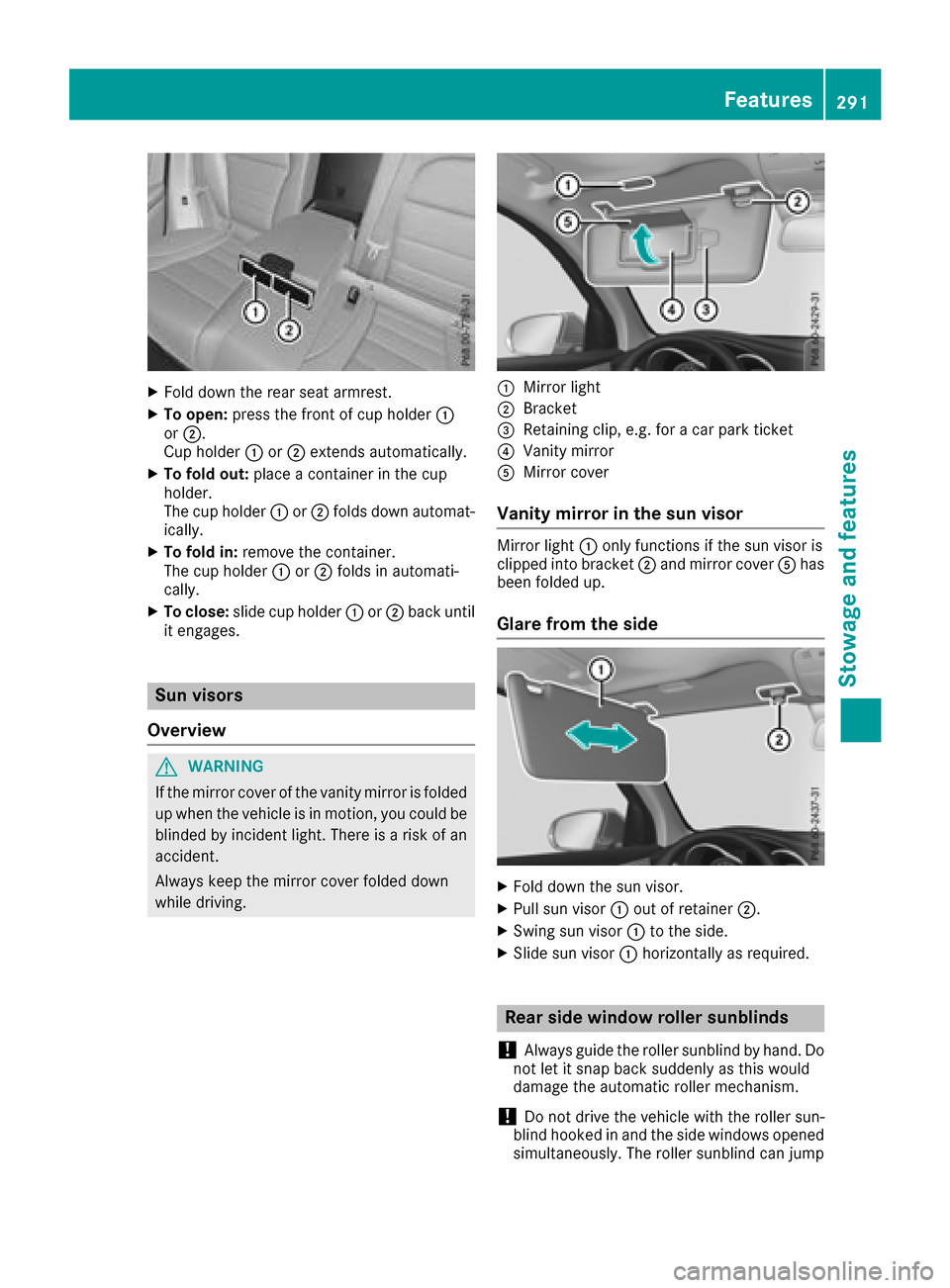
XFold down the rear seat armrest.
XTo open:press the front of cup holder :
or ;.
Cup holder :or; extends automatically.
XTo fold out: place a container in the cup
holder.
The cup holder :or; folds down automat-
ically.
XTo fold in: remove the container.
The cup holder :or; folds in automati-
cally.
XTo close: slide cup holder :or; back until
it engages.
Sun visors
Overview
GWARNING
If the mirror cover of the vanity mirror is folded
up when the vehicle is in motion, you could be
blinded by incident light. There is a risk of an
accident.
Always keep the mirror cover folded down
while driving.
:Mirror light
;Bracket
=Retaining clip, e.g. for a car park ticket
?Vanity mirror
AMirror cover
Vanity mirror in the sun visor
Mirror light :only functions if the sun visor is
clipped into bracket ;and mirror cover Ahas
been folded up.
Glare from the side
XFold down the sun visor.
XPull sun visor :out of retainer ;.
XSwing sun visor :to the side.
XSlide sun visor :horizontally as required.
Rear side window roller sunblinds
!
Always guide the roller sunblind by hand. Do
not let it snap back suddenly as this would
damage the automatic roller mechanism.
!Do not drive the vehicle with the roller sun-
blind hooked in and the side windows opened
simultaneously. The roller sunblind can jump
Features291
Stowage and features
Z