2017 MERCEDES-BENZ GLA SUV trailer
[x] Cancel search: trailerPage 332 of 369
The brackets for the screw-in towing eye are
located in the bumpers. They are located at the rear and at the front, under covers :.
X Remove the towing eye from the stowage
space.
The towing eye is located with the vehicle tool
kit under the luggage compartment floor
(Y page 317).
Vehicles with a TIREFIT kit: the towing eye is
located under the tyre inflation compressor
(Y page 317).
X Press the mark on cover :inwards in the
direction of the arrow.
X Remove cover :from the opening.
X Screw in the towing eye clockwise to the stop.
Vehicles with a trailer tow hitch only have a
bracket at the front for the screw-in towing eye.
If you intend to use the vehicle for towing, fold
out the ball coupling (Y page 214) and secure
the towbar to it.
Removing the towing eye X
Loosen the towing eye and unscrew it.
X Attach cover :to the bumper and press until
it engages.
X Place the towing eye in the stowage well
under the luggage compartment floor
(Y page 317).
X Vehicles with a TIREFIT kit: replace the tyre
inflation compressor (Y page 317).Towing the vehicle with the front axle
raised
When towing your vehicle with the front axle
raised, it is important that you observe the
safety instructions (Y page 327).
Only vehicles without 4MATIC can be towed
with the front axle raised.
! Vehicles with 4MATIC must not be towed
with the front or rear axle raised; otherwise,
the transmission may be damaged.
Vehicles with 4MATIC may either be towed with
both axles on the ground or be loaded and trans- ported.
! The ignition must be switched off if you are
towing the vehicle with the front axle raised. Intervention by ESP
®
could otherwise dam-
age the brake system.
X On vehicles with KEYLESS-GO or the KEY-
LESS-GO start function: you must use the
key instead of the Start/Stop button
(Y page 145).
X Make sure that the vehicle is stationary.
X Turn the key to position 2in the ignition
lock.
X When the vehicle is stationary, depress the
brake pedal and keep it depressed.
X Vehicles with automatic transmission:
shift the automatic transmission to position
j.
or X Vehicles with manual transmission:
depress the clutch pedal fully and shift to
neutral.
X Release the brake pedal.
X Release the electric parking brake.
X Deactivate tow-away protection (Y page 77).
X Deactivate automatic locking (Y page 229).
X Switch on the hazard warning lamps
(Y page 118).
X Turn the key in the ignition lock to position g
and leave the key in the ignition lock. Towing the vehicle away with all
wheels on the ground
It is important that you observe the safety
instructions when towing away your vehicle
(Y page 327).
X On vehicles with KEYLESS-GO or the KEY-
LESS-GO start function: you must use the
key instead of the Start/Stop button
(Y page 145).
Vehicles with automatic transmission: The
automatic transmission automatically shifts to
position jwhen you open the driver's or front-
passenger door or when you remove the key
from the ignition lock. In order to ensure that the
automatic transmission stays in position i
when towing away the vehicle, you must
observe the following points:
X Make sure that the vehicle is stationary.
X Turn the key to position 2in the ignition
lock. Towing away and tow-starting
329Breakdown assistance Z
Page 333 of 369
X
Depress the brake pedal and keep it
depressed.
X Shift the automatic transmission to position
i.
Vehicles with manual transmission: X Turn the key to position 2in the ignition
lock.
X When the vehicle is stationary, depress the
brake pedal and keep it depressed.
X Depress the clutch pedal fully and engage
neutral.
Vehicles with manual or automatic trans-
mission:
X Leave the key in position 2in the ignition
lock.
X Release the brake pedal.
X Release the electric parking brake.
X Switch on the hazard warning lamps
(Y page 118).
i In order to signal a change of direction when
towing the vehicle with the hazard warning
lamps switched on, use the combination
switch as usual. In this case, only the turn
signals for the desired direction flash. When
you reset the combination switch, the hazard warning lamps start flashing again. Transporting the vehicle
4MATIC vehicles or vehicles with auto-
matic transmission !
When the vehicle is loaded for transport, the
front and rear axles must be stationary and on
the same transportation vehicle. Positioning
over the connection point of the transport
vehicle is not permitted. The drive train may
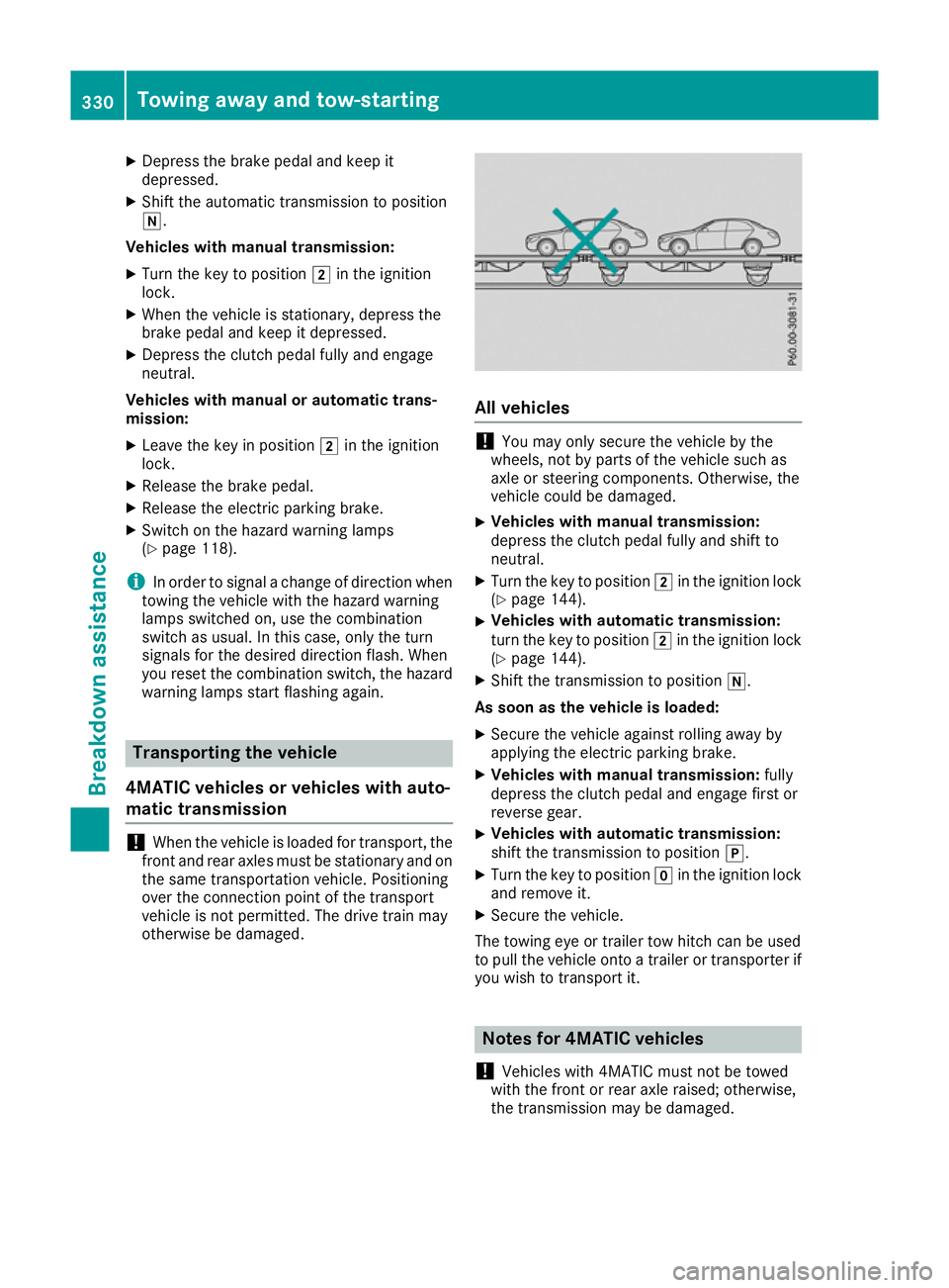
otherwise be damaged. All vehicles
!
You may only secure the vehicle by the
wheels, not by parts of the vehicle such as
axle or steering components. Otherwise, the
vehicle could be damaged.
X Vehicles with manual transmission:
depress the clutch pedal fully and shift to
neutral.
X Turn the key to position 2in the ignition lock
(Y page 144).
X Vehicles with automatic transmission:
turn the key to position
2in the ignition lock
(Y page 144).
X Shift the transmission to position i.
As soon as the vehicle is loaded:
X Secure the vehicle against rolling away by
applying the electric parking brake.
X Vehicles with manual transmission: fully
depress the clutch pedal and engage first or
reverse gear.
X Vehicles with automatic transmission:
shift the transmission to position
j.
X Turn the key to position gin the ignition lock
and remove it.
X Secure the vehicle.
The towing eye or trailer tow hitch can be used
to pull the vehicle onto a trailer or transporter if
you wish to transport it. Notes for 4MATIC vehicles
! Vehicles with 4MATIC must not be towed
with the front or rear axle raised; otherwise,
the transmission may be damaged. 330
Towing away and tow-startingBreakdown assistance
Page 334 of 369
Vehicles with 4MATIC may only be either towed
away with both axles on the ground or be loadedup and transported.
If the vehicle has transmission damage or dam-
age to the front or rear axle, have it transported on a transporter or trailer.
In the event of damage to the electrical sys-
tem:
If the battery is defective, the automatic trans-
mission will be locked in position j. To shift the
automatic transmission to position i, you
must provide power to the vehicle's on-board
electrical system in the same way as when jump- starting (Y page 325).
Have the vehicle transported on a transporter or trailer. Tow-starting (emergency engine
starting)
! Do not tow-start vehicles with automatic
transmission. You could otherwise damage
the automatic transmission.
i You can find information on "Jump-starting"
under (Y page 325).
Before tow-starting, the following conditions
must be fulfilled: R the battery is connected
R the engine has cooled down
R the exhaust system has cooled down
When tow-starting, it is important that you
observe the safety notes (Y page 327) and the
legal requirements in each respective country.
X Switch on the hazard warning lamps
(Y page 118).
X Fit the towing eye (Y page 328).
X Secure the rigid towing bar or the towing
rope.
X When the vehicle is stationary, depress the
brake pedal and keep it depressed.
X Turn the key to position 2in the ignition lock
(Y page 144).
X Depress the clutch pedal fully, engage second
gear and continue to keep the clutch pedal
fully depressed.
X Release the brake pedal.
X Tow-start the vehicle.
X Release the clutch pedal slowly; do not
depress the accelerator pedal while doing so. X
When the engine has been started, immedi-
ately depress the clutch pedal fully and shift
to neutral.
X Pull over at a suitable place and stop the vehi-
cle safely, paying attention to road and traffic
conditions.
X Use the electric parking brake to secure the
vehicle and prevent it from rolling away.
X Remove the rigid towing bar or towing rope.
X Remove the towing eye (Y page 329).
X Switch off the hazard warning lamps. Fuses
Important safety notes
G
WARNING
If you manipulate, bridge or replace a faulty
fuse with a fuse of a higher amperage, the
electric cables could be overloaded. This may result in a fire. There is a risk of an accident
and injury.
Always replace faulty fuses with specified newfuses of the correct amperage.
! Only use fuses that have been approved for
Mercedes-Benz vehicles and which have the
correct fuse rating for the system concerned.
Only use fuses marked with an "S". Compo-
nents or systems could otherwise be dam-
aged.
! Make sure that no moisture can enter the
fuse box when the cover is open.
! When closing the cover, make sure that it is
lying correctly on the fuse box. Moisture seep-
ing in or dirt could otherwise impair the oper- ation of the fuses.
The fuses in your vehicle disconnect faulty cir-
cuits. If a fuse blows, all the components in the circuit and their functions will fail.
Blown fuses must be replaced with fuses of the same rating, which you can recognise by the
colour and fuse rating. The fuse ratings are listed
in the fuse allocation chart.
The fuse allocation chart is in the fuse box in the front-passenger footwell (Y page 332).
If the newly inserted fuse also blows, have the
cause traced and rectified at a qualified special- Fuses
331Breakdown assistance Z
Page 341 of 369
Only screw standard valve caps or valve caps
specifically provided by Mercedes-Benz for
your vehicle onto the tyre valve. G
WARNING
If the tyre pressure drops repeatedly, the
wheel, valve or tyre may be damaged. Tyre
pressure that is too low may result in a tyre
blow-out. There is a risk of accident.
R Check the tyre for foreign objects.
R Check whether the wheel is losing air or the
valve is leaking.
If you are unable to rectify the damage, con-
tact a qualified specialist workshop. H
Environmental note
Check the tyre pressure regularly, at least
every 14 days.
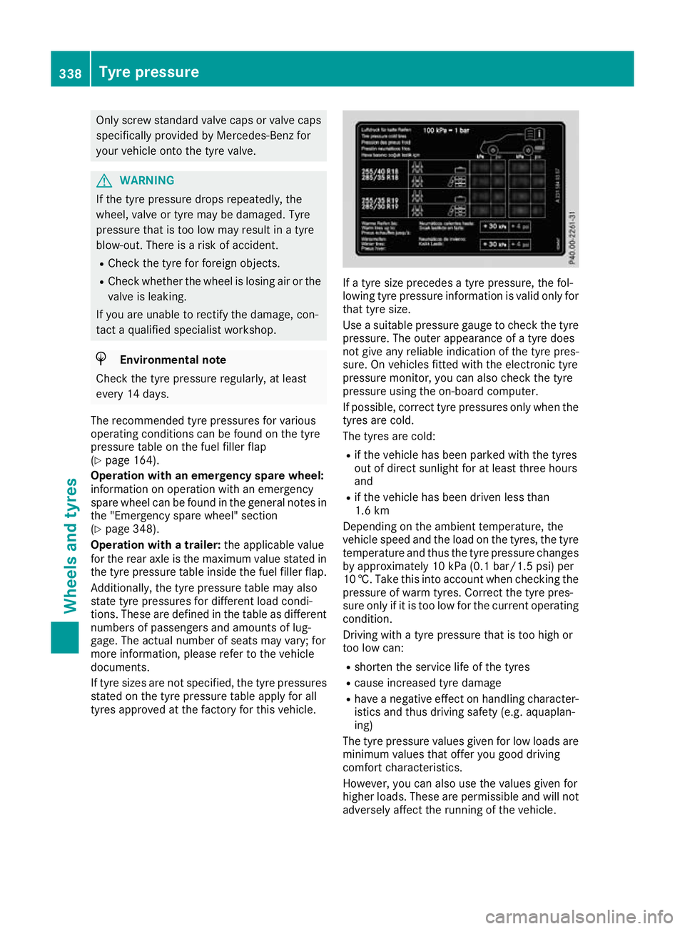
The recommended tyre pressures for various
operating conditions can be found on the tyre
pressure table on the fuel filler flap
(Y page 164).
Operation with an emergency spare wheel:
information on operation with an emergency
spare wheel can be found in the general notes in the "Emergency spare wheel" section
(Y page 348).
Operation with a trailer: the applicable value
for the rear axle is the maximum value stated in the tyre pressure table inside the fuel filler flap.
Additionally, the tyre pressure table may also
state tyre pressures for different load condi-
tions. These are defined in the table as different numbers of passengers and amounts of lug-
gage. The actual number of seats may vary; for
more information, please refer to the vehicle
documents.
If tyre sizes are not specified, the tyre pressures
stated on the tyre pressure table apply for all
tyres approved at the factory for this vehicle. If a tyre size precedes a tyre pressure, the fol-
lowing tyre pressure information is valid only for that tyre size.
Use a suitable pressure gauge to check the tyre
pressure. The outer appearance of a tyre does
not give any reliable indication of the tyre pres-
sure. On vehicles fitted with the electronic tyre
pressure monitor, you can also check the tyre
pressure using the on-board computer.
If possible, correct tyre pressures only when the
tyres are cold.
The tyres are cold:
R if the vehicle has been parked with the tyres
out of direct sunlight for at least three hours
and
R if the vehicle has been driven less than
1.6 km
Depending on the ambient temperature, the
vehicle speed and the load on the tyres, the tyre temperature and thus the tyre pressure changes by approximately 10 kPa (0.1 bar/1.5 psi) per
10 †. Take this into account when checking the
pressure of warm tyres. Correct the tyre pres-
sure only if it is too low for the current operating
condition.
Driving with a tyre pressure that is too high or
too low can:
R shorten the service life of the tyres
R cause increased tyre damage
R have a negative effect on handling character-
istics and thus driving safety (e.g. aquaplan-
ing)
The tyre pressure values given for low loads are minimum values that offer you good driving
comfort characteristics.
However, you can also use the values given for
higher loads. These are permissible and will not
adversely affect the running of the vehicle. 338
Tyre pressureWheels and tyres
Page 342 of 369
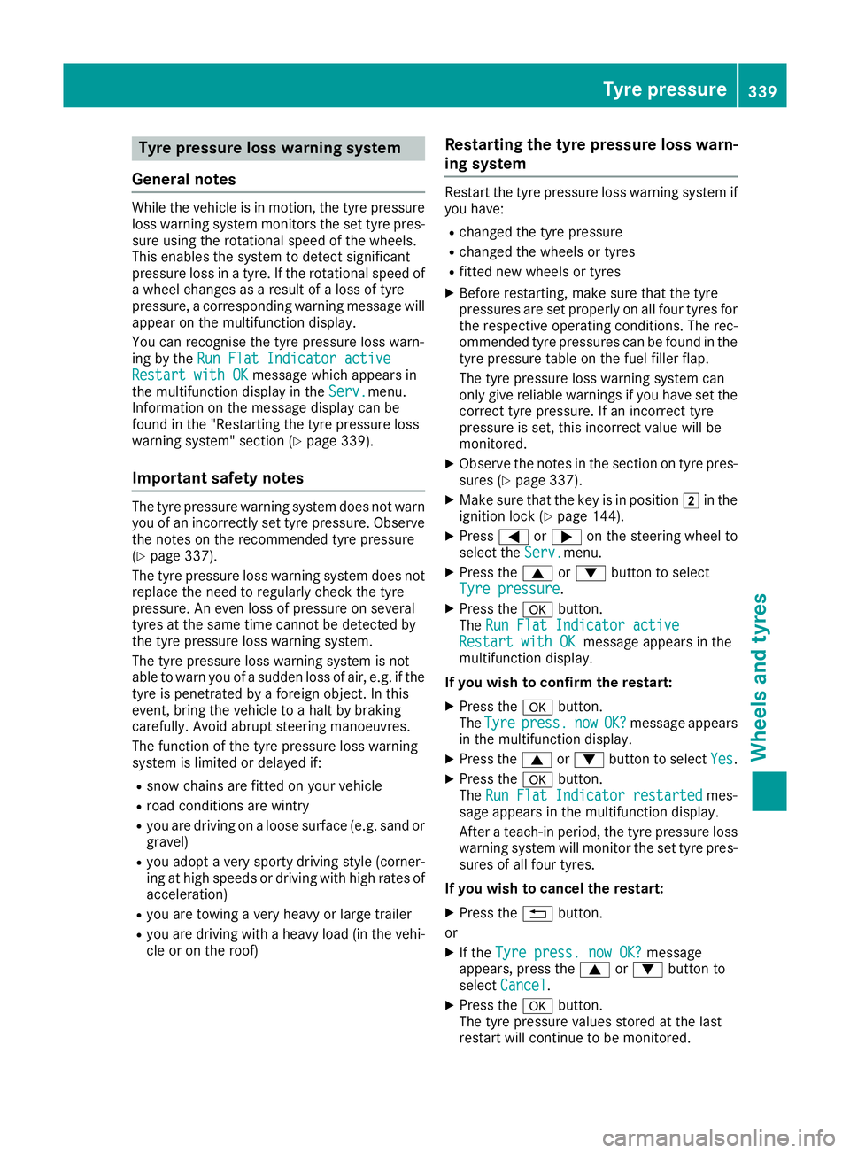
Tyre pressure loss warning system
General notes While the vehicle is in motion, the tyre pressure
loss warning system monitors the set tyre pres-
sure using the rotational speed of the wheels.
This enables the system to detect significant
pressure loss in a tyre. If the rotational speed of
a wheel changes as a result of a loss of tyre
pressure, a corresponding warning message will
appear on the multifunction display.
You can recognise the tyre pressure loss warn-
ing by the Run Flat Indicator active
Run Flat Indicator active
Restart with OK Restart with OK message which appears in
the multifunction display in the Serv.
Serv.menu.
Information on the message display can be
found in the "Restarting the tyre pressure loss
warning system" section (Y page 339).
Important safety notes The tyre pressure warning system does not warn
you of an incorrectly set tyre pressure. Observe the notes on the recommended tyre pressure
(Y page 337).
The tyre pressure loss warning system does not
replace the need to regularly check the tyre
pressure. An even loss of pressure on several
tyres at the same time cannot be detected by
the tyre pressure loss warning system.
The tyre pressure loss warning system is not
able to warn you of a sudden loss of air, e.g. if the
tyre is penetrated by a foreign object. In this
event, bring the vehicle to a halt by braking
carefully. Avoid abrupt steering manoeuvres.
The function of the tyre pressure loss warning
system is limited or delayed if:
R snow chains are fitted on your vehicle
R road conditions are wintry
R you are driving on a loose surface (e.g. sand or
gravel)
R you adopt a very sporty driving style (corner-
ing at high speeds or driving with high rates of
acceleration)
R you are towing a very heavy or large trailer
R you are driving with a heavy load (in the vehi-
cle or on the roof) Restarting the tyre pressure loss warn-
ing system Restart the tyre pressure loss warning system if
you have:
R changed the tyre pressure
R changed the wheels or tyres
R fitted new wheels or tyres
X Before restarting, make sure that the tyre
pressures are set properly on all four tyres for
the respective operating conditions. The rec-
ommended tyre pressures can be found in the
tyre pressure table on the fuel filler flap.
The tyre pressure loss warning system can
only give reliable warnings if you have set the correct tyre pressure. If an incorrect tyre
pressure is set, this incorrect value will be
monitored.
X Observe the notes in the section on tyre pres-
sures (Y page 337).
X Make sure that the key is in position 2in the
ignition lock (Y page 144).
X Press =or; on the steering wheel to
select the Serv. Serv.menu.
X Press the 9or: button to select
Tyre pressure
Tyre pressure.
X Press the abutton.
The Run Flat Indicator active
Run Flat Indicator active
Restart with OK
Restart with OK message appears in the
multifunction display.
If you wish to confirm the restart: X Press the abutton.
The Tyre
Tyre press.
press. now
nowOK?
OK?message appears
in the multifunction display.
X Press the 9or: button to select Yes
Yes.
X Press the abutton.
The Run Flat Indicator restarted
Run Flat Indicator restarted mes-
sage appears in the multifunction display.
After a teach-in period, the tyre pressure loss warning system will monitor the set tyre pres-
sures of all four tyres.
If you wish to cancel the restart: X Press the %button.
or X If the Tyre press. now OK?
Tyre press. now OK? message
appears, press the 9or: button to
select Cancel Cancel .
X Press the abutton.
The tyre pressure values stored at the last
restart will continue to be monitored. Tyre pressure
339Wheels and tyres Z
Page 354 of 369
tion of aftermarket radio frequency transmitting
equipment") when retrofitting RF transmitters.
Comply with the legal requirements for add-on
parts.
If your vehicle has fittings for two-way radio
equipment, use the power supply or aerial con-
nections intended for use with the basic fittings.
Be sure to observe the manufacturer's addi-
tional instructions when installing.
Deviations in respect of wavebands, maximum
transmission outputs or aerial positions must be approved by Mercedes-Benz.
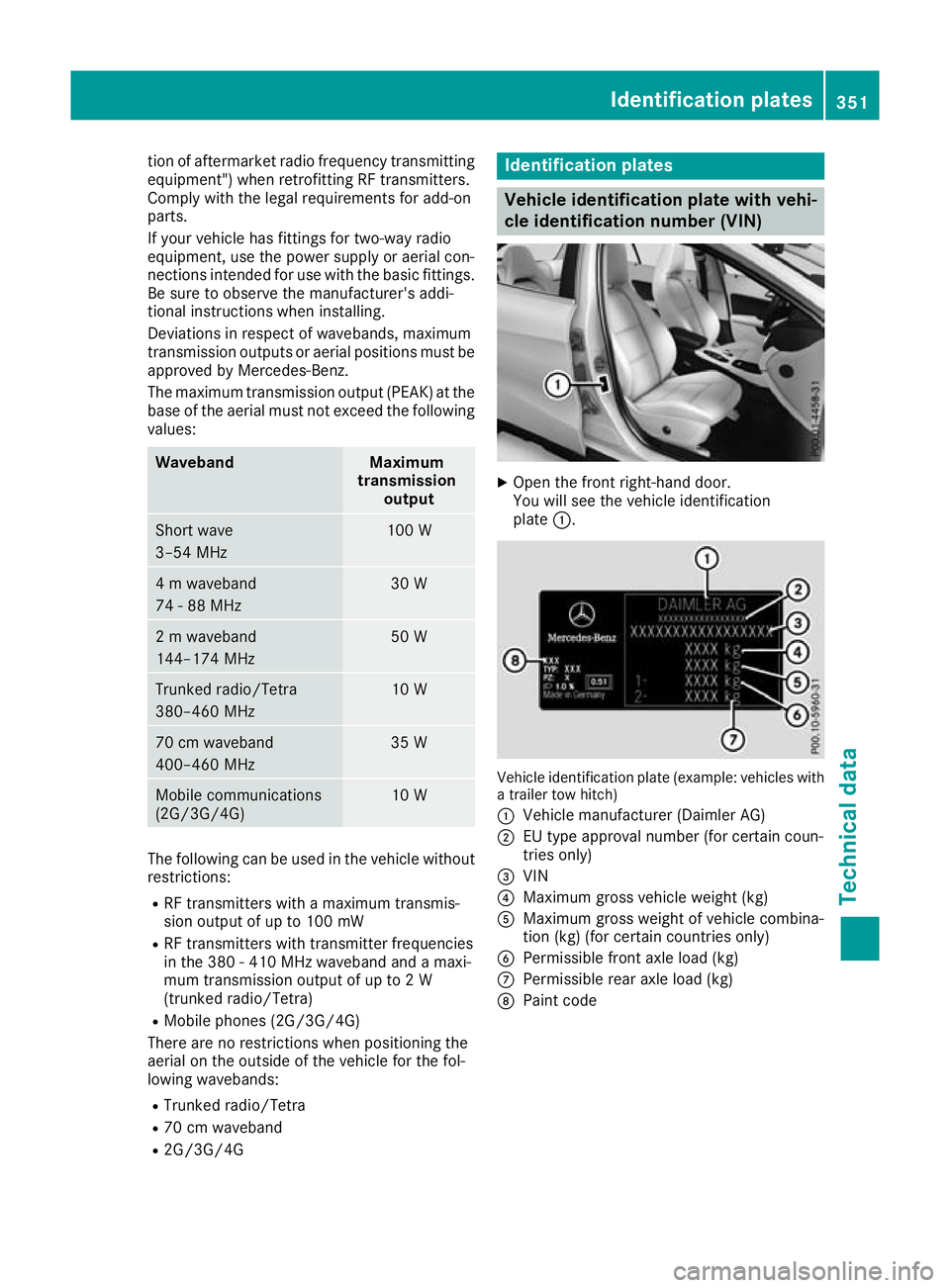
The maximum transmission output (PEAK) at the base of the aerial must not exceed the followingvalues: Waveband Maximum
transmission output Short wave
3–54 MHz 100 W
4 m waveband
74 - 88 MHz 30 W
2 m waveband
144–174 MHz 50 W
Trunked radio/Tetra
380–460 MHz 10 W
70 cm waveband
400–460 MHz 35 W
Mobile communications
(2G/3G/4G) 10 W
The following can be used in the vehicle without
restrictions:
R RF transmitters with a maximum transmis-
sion output of up to 100 mW
R RF transmitters with transmitter frequencies
in the 380 - 410 MHz waveband and a maxi-
mum transmission output of up to 2 W
(trunked radio/Tetra)
R Mobile phones (2G/3G/4G)
There are no restrictions when positioning the
aerial on the outside of the vehicle for the fol-
lowing wavebands:
R Trunked radio/Tetra
R 70 cm waveband
R 2G/3G/4G Identification plates
Vehicle identification plate with vehi-
cle identification number (VIN)
X
Open the front right-hand door.
You will see the vehicle identification
plate :. Vehicle identification plate (example: vehicles with
a trailer tow hitch)
: Vehicle manufacturer (Daimler AG)
; EU type approval number (for certain coun-
tries only)
= VIN
? Maximum gross vehicle weight (kg)
A Maximum gross weight of vehicle combina-
tion (kg) (for certain countries only)
B Permissible front axle load (kg)
C Permissible rear axle load (kg)
D Paint code Identification plates
351Technical data Z
Page 362 of 369
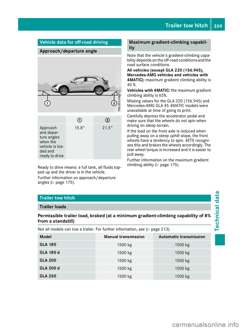
Vehicle data for off-road driving
Approach/departure angle
:
: ;
;
Approach
and depar-
ture angles
when the
vehicle is loa-
ded and
ready to drive 15.8° 21.5°
Ready to drive means: a full tank, all fluids top-
ped up and the driver is in the vehicle.
Further information on approach/departure
angles (Y page 175). Maximum gradient-climbing capabil-
ity
Note that the vehicle's gradient-climbing capa-
bility depends on the off-road conditions and the road surface conditions.
All vehicles (except GLA 220 (156.945),
Mercedes-AMG vehicles and vehicles with
4MATIC): maximum gradient climbing ability is
40 %.
Vehicles with 4MATIC: the maximum gradient
climbing ability is 65%.
Missing values for the GLA 220 (156.945) and
Mercedes‑AMG GLA 45 4MATIC models were
unavailable at time of going to print.
Carefully depress the accelerator pedal and
make sure that the wheels do not spin when
driving on steep terrain.
If the load on the front axle is reduced when
pulling away on a steep uphill slope, the front
wheels have a tendency to spin. 4ETS recogni-
ses this and brakes the wheels accordingly. The
rear wheel torque is increased and it is easier to pull away.
Further information on the maximum gradient
climbing ability (Y page 175). Trailer tow hitch
Trailer loads
Permissible trailer load, braked (at a minimum gradient-climbing capability of 8%
from a standstill) Not all models can tow a trailer. For further information, see (Y
page 213).Model Manual transmission Automatic transmission
GLA 180
1500 kg 1500 kg
GLA 180 d
1500 kg 1500 kg
GLA 200
1500 kg 1500 kg
GLA 200 d
1500 kg 1500 kg
GLA 250
1500 kg 1500 kgTrailer tow hitch
359Technical data Z
Page 363 of 369
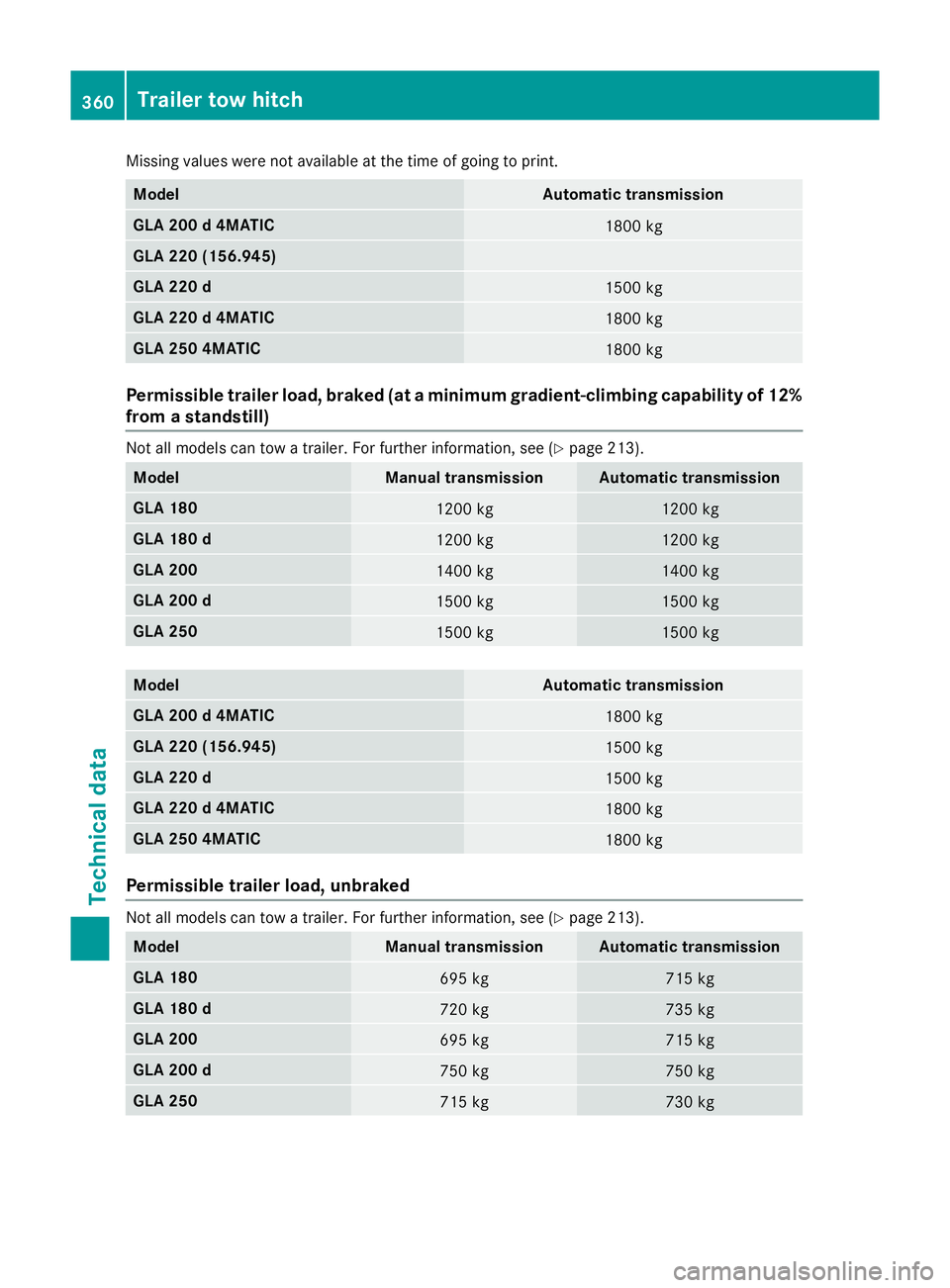
Missing values were not available at the time of going to print.
Model Automatic transmission
GLA 200 d 4MATIC
1800 kg
GLA 220 (156.945)
GLA 220 d
1500 kg
GLA 220 d 4MATIC
1800 kg
GLA 250 4MATIC
1800 kg
Permissible trailer load, braked (at a minimum gradient-climbing capability of 12%
from a standstill) Not all models can tow a trailer. For further information, see (Y
page 213).Model Manual transmission Automatic transmission
GLA 180
1200 kg 1200 kg
GLA 180 d
1200 kg 1200 kg
GLA 200
1400 kg 1400 kg
GLA 200 d
1500 kg 1500 kg
GLA 250
1500 kg 1500 kg
Model Automatic transmission
GLA 200 d 4MATIC
1800 kg
GLA 220 (156.945)
1500 kg
GLA 220 d
1500 kg
GLA 220 d 4MATIC
1800 kg
GLA 250 4MATIC
1800 kg
Permissible trailer load, unbraked
Not all models can tow a trailer. For further information, see (Y
page 213).Model Manual transmission Automatic transmission
GLA 180
695 kg 715 kg
GLA 180 d
720 kg 735 kg
GLA 200
695 kg 715 kg
GLA 200 d
750 kg 750 kg
GLA 250
715 kg 730 kg360
Trailer tow hitchTechnical data