2017 MERCEDES-BENZ E43AMG IDENTIFICATION
[x] Cancel search: IDENTIFICATIONPage 5 of 482

Drivingand pa rking ................................. 129
Driving ........................................................ 129
DY NA MIC SELECT switch ............................1 36
Au tomatic transmission .............................. 137
Re fueling ..................................................... 141
Pa rking ...................................................... .143
Driving and driving saf etysy stems ............ .150
Instrument Display and on-board
comp uter .................................................. 199
Instrument Display overview ...................... .199
Overview of the buttons on thesteering
wheel ......................................................... .200
Operating the on-board computer .............. 201
Displa ysinthe multifunction display ......... .202
Ad justing the instrument lighting ............... 203
Menus and submenus ................................ 203
Head-up Display .......................................... 210
Vo ice Control Sy stem ............................... 212
Operating saf ety.......................................... 212
Operation ....................................................2 12
Using Voice Cont rol Sy stem ef fectively ....... 214
Essential commands ................................... 214
Multimedia sy stem .................................. 223
Overview and operation .............................. 223
Sy stem settings .......................................... 231
Na vigation .................................................. 239
Te lephone .................................................. .260
Online and Internet functions ..................... 274
Media ..........................................................2 81
Ra dio .......................................................... 293
Sound ........................................................ .300
Maintenance and care .............................303
ASS YST PLUS service inter val display ........ 303
Engine compartment .................................. 304
Cleaning and care ...................................... .310
Breakdown assistance .............................318
Emergency .................................................. 318
Flat tire ....................................................... 318
Battery (vehicle) .........................................3 24
To w starting or towing away ....................... 329
Electrical fuses ........................................... 334
Wheels and tires ...................................... 338
Noise or unusual handling characteris‐
tics ............................................................ .338
Re gular checking of wheels and tires ......... 338
No tes on snow chains ................................ 339
Ti re pressure .............................................. 339
Loading theve hicle .................................... 345
Ti re labeling ................................................ 350
Definitions for tires and loading ................. 355
Changing a wheel ....................................... 358
Te ch nical data .......................................... 368
No tes on tech nical da ta.............................. 368
Ve hicle electronics .....................................3 68
Ve hicle identification plate, VIN and
engine number ...........................................3 70
Operating fluids .......................................... 372
Ve hicle data ................................................ 378
Displa ymessages and warning/indi‐
cator lamps .............................................. 380
Display messages ...................................... .380
Wa rning and indicator lamps ...................... 423
Contents 3
Page 22 of 482

*NO
TEImpairment of the operating ef fi‐
ciency of there stra int sy stems from
ins talling accessories or from repairs or
we lding
Airbags, Emer gency Tensioning Devices, as
we ll as control units and sensors forth e
re stra int sy stems, may be ins talled in thefo l‐
lowing areas of your vehicle:
RDoors
RDoor pillars
RDoor sills
RSeats
RCo ckpit
RInstrument clus ter
RCente r console
#Do not ins tall accessories such as audio
sy stems in these areas.
#Do not car ryout repairs or welding.
#Have accessori esretrofitted at a quali‐
fi ed specialist workshop.
Yo u could jeopardize the operating saf etyof your
ve hicle if you use parts, tires and wheels as well
as accessories releva nt tosaf etywhic hha ve not
been appr ovedby Mercedes-Benz. This could
lead tomalfunctions in saf ety-re leva nt sy stems,
fo rex ample, the brake sy stem. Only use
Mercedes-Benz GenuineParts or parts of equal
qu ality. Only use tires, wheels and accessory
parts that ha vebeen specifically appr ovedfo r
yo ur vehicle model.
Mercedes-Benz GenuineParts are subject to
st rict quality control. Each part has been spe‐
cially de veloped, manufactured or selecte dfo r
Mercedes-Benz vehicles and fine-tuned forth em.
Therefore, only Mercedes-Benz GenuineParts
should be used.
More than 300,000 dif fere nt Mercedes-Benz
GenuineParts are available for Mercedes-Benz
models.
All au thorized Mercedes-Benz Centers maintain
a supply of Mercedes-Benz GenuineParts for
necessary service and repair work. In addition,
st ra tegically located parts-delivery centers pro‐
vide forqu ick and reliable parts service. Alw
ays specify theve hicle identification number
(VIN) (→page 370) when orde ring Mercedes-
Benz GenuineParts.
Ope rato r's Manual
This Operator's Manual describes all models and
all standard and optional equipment available for
yo ur vehicle at the time of this Opera tor's Man‐
ual going topress. Countr y-specific dif fere nces
are possible. No tethat your vehicle may not be
equipped with all features descri bed. This is also
th e case for sy stems and functions releva nt to
saf ety. Therefore, the equipment on your vehicle
may dif fer from that in the descriptions and illus‐
trations.
The original pur chase contract documentation
fo ryo ur vehicle contains a list of all of the sys‐
te ms in your vehicle.
Should you ha veany questions concerning
equipment and operation, please consult an
authorized Mercedes-Benz service center.
The Operator's Manual and maintenance booklet
are impor tant documents and should be kept in
th eve hicle.
20
General no tes
Page 98 of 482
&WARNING Risk of injury from unsecured
items in theve hicle
If objects, luggage or loads are not secured
or not secured suf ficientl y,they could slip,
tip ove r or be throw n around and thereby hit
ve hicle occupants.
There is a risk of injur y,particularly in the
ev ent of sudden braking or a sudden change
in direction.
#Alw aysstow objects in such a wayth at
th ey cannot be thro wn around.
#Before the journe y,secure objects, lug‐
ga ge or loads against slipping or tipping
ove r.
&
WARNING Risk of injury from incorrectly
stowe d objects
If objects in theve hicle interior are stowed
incor rectly, they can slide or be throw n
around and hit vehicle occupants. In addi‐
tion, cup holders, open stowage spaces and
mobile phone brac kets cann otalw aysre tain
all objects they contain.
There is arisk of injur y,particularly in the
ev ent of sudden braking or a sudden change
in direction.
#Alw aysstow objects so that they can‐
not be throw n around in such situa‐
tions.
#Alw ays make sure that objects do not
pr otru de from stowage spaces, luggage
nets or stowage nets.
#Close the loc kable stow age spaces
before starting a journe y.
#Alwaysstow and secure heavy, hard,
pointe d, sharp-edged, fragile or bulky
objects in the trunk.
&
WARNING Risk of burn s fromtailpipes
and tailpipe trim
The tailpipe and tailpipe trim can become
ve ry hot. If you come into contact withth ese
parts of theve hicle, you could burn yourself.
#Alw ays be particular lycareful around
th eta ilpipe and theta ilpipe trim.
#Allow theve hicle parts tocool down
before youto uch them.
The handling characteristics of your vehicle are
dependent on the distribution of the load within
th eve hicle. You should bear thefo llowing in
mind when loading theve hicle:
RNe verex ceed the permissible gross mass or
th e permissible axle load forth eve hicle
(including occupants). The values are speci‐
fi ed on theve hicle identification plate on the
ve hicle's B-pillar.
RThe load must not pr otru de abo vethe upper
edge of the seat backrests.
RAlw ays place the load behind unoccupied
seats if possible.
RSecure the load using the tie-down eye and
distribute the load evenly.
96
Seats and stowing
Page 275 of 482
Automatic eme rgency call
The emer gency call is initia ted:
RWhen an airbag is deplo yed.
RWhen the Emer gency Tensioning Devices are
trig gered.
Yo u can end an automatically initiated emer‐
ge ncy call yourself af ter 60 seconds.
Manual emer gency call
An emer gency call can be initia ted manually via
th e SOS button in theove rhead control panel
(
→page 272).
If yo u lea vetheve hicle immediately af ter press‐
ing the SOS button, youdo not kn owif
Mercedes-Benz mbrace
®has successfully made
th e emer gency call.
Initiated eme rgency call
A vo ice connection between the Cus tomer Assis‐
ta nce Center and theve hicle occupants is es tab‐
lished:
Rif th eve hicle occupants are responsive, the
Mercedes-Benz Cus tomer Assis tance Center asks
for more de tailed information on the
emer gency.
Rif no vehicle occupant answers, an ambu‐
lance is sent totheve hicle immediatel y.
Tr ansfer red data
During thevo ice connection tothe Cus tomer
Assis tance Center, thefo llowing data is transfer‐
re d:
RCur rent vehicle location
RVe hicle identification number
Emer gency call not possible
Rifth e mobile phone network is una vailable,
Mercedes-Benz mbrace®is not able tomake
an emer gency call.
A message tothis ef fect is shown in the mul‐
tifunction displa y.
The indicator lamp flashes continuousl y.
In this c
ase, seek assis tance by ot her means.
Information on the MB Info call
An Info calltothe Mercedes-Benz Cus tomer
Assis tance Center has been initiate d viathe
ove rhead control panel (
→page 272). Yo
u can find information on thefo llowing topics:
RAc tivating Merc edes-Benz mbrace®
ROperatingtheve hicle
RNearest authorized Mercedes-Benz Center
ROther products and services from
Mercedes-Benz
Data is transmitted during the connection tothe
Mercedes-Benz Cus tomer Assis tance Center
(
→pa ge 274).
Information on theRo adside Assistance call
A Ro adside Assis tance call tothe Mercedes-
Benz Cus tomer Assis tance Center has been initi‐
ated via theov erhead control panel:
RThe problem with theve hicle is analyzed
using remo tediagnosis.
Fu rther information about this can be
obtained at: http://www.mbusa.com
RA qu alified Mercedes-Benz tech nician car ries
out repairs on site and/or theve hicle will be
to we dto the nearest authorized
Mercedes-Benz Center.
Yo u may be charge dfo rth ese services.
Multimedia sy stem 27
3
Page 348 of 482
#Observethe load rating of the tires.
#The load rating must be at least half the
permissible axle load of theve hicle.
#Ne verove rload the tires by exceeding
th e maximum load.
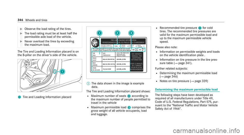
The Tire and Loading Info rmation placard is on
th e B-pillar on the driver's side of theve hicle.
1Tire and Loading Info rmation placard
%
The data shown in the image is example
data.
The Tire and Loading Info rmation placard sho ws:
RMaximum number of seats 2according to
th e maximum number of people permitted to
tr ave l in theve hicle
RMaximum permissible load 3comprises the
gross weight of all vehicle occupants, load
and luggage.
RRe commended tire pressure 1for cold
tires. The recommended tire pressures are
va lid forth e maximum permissible load and
up tothe maximum permissible vehicle
speed.
Please also no te:
RInformation on permissible weights and loads
on theve hicle identification plate .
RInformation on tire pressure in the tire pres‐
sure table (→page 341).
Fu rther related subjects:
RDe term ining the maximum permissible load
(→page 346)
RNo tes on tire pressure (→page 339)
De term ining the maximum permissible load
The following steps ha vebeen de veloped as
re qu ired of all manufacturers under Title 49,
Code of U.S. Federal Regulations, Part57 5, pur‐
suant tothe "National Traf fic and Mo torVe hicle
Saf etyAc t of 1966".
34 6
Wheels and tires
Page 349 of 482
#Step 1: Locate thest atement "The combined
we ight of occupants and cargo should ne ver
exc eed XXX kgor XXX lbs." ("The combined
we ight of occupants and cargo should ne ver
exc eed XXX kgor XXX lbs.") on your vehicle's
tire and loading information table.
#Ste p 2: Determ ine the combined weight of
th e driver and passengers that will be riding
in your vehicle.
#Ste p 3: Subtract the combined weight of the
driver and passengers from XXX kgor
XXX lbs.
#Ste p 4: Theresulting figure equals the per‐
missible load for cargo and lug gage .Fo r
ex ample: If "XXX" equals 1400 lbs and there
are five occupants in your vehicle with a
we ight of 150 lbs each, the maximum cargo
and luggage load capacity is 650 lbs (1400 -
75 0 (5 x 150) = 650 lbs).
#Ste p 5: Determ ine the combined weight of
luggage and cargo being car ried in theve hi‐
cle. For saf etyre asons, this we ight may not
safely exceed theav ailable cargo and lug‐
ga ge load capacity calculated in step 4. Even if
you ha vecalculated thetot al load care‐
full y,yo u should still make sure that the maxi‐
mum permissible gross mass and the maximum
permissible axle load of your vehicle are not
exc eeded. De tails can be found on theve hicle
identification plate.
#Ha ve your loaded vehicle – including driver,
occupants and load – weighed on a vehicle
we ighbridge.
The measured values may not exceed the
maximum permissible values stated on the
ve hicle identification plate.
Fu rther related subjects:
RCalculation example for de term ining the max‐
imum load (→page 347)
RTi re and Loading Info rmation placard
(→page 345)
RTi re pressure table (→page 341)
RVe hicle identification plate
Calculation example for de term ining the
ma ximum load
The following table sho wsexamples of how to
calculate tota l and load capacities with varying
seating con figurations and dif fere nt numbe rs
and sizes of occupants. The following examples
use a maximum load of 1500 lbs (680 kg).This
is for illustration purposes on ly.Make sure
yo u are using the actual load limit foryo ur vehi‐
cle stated on your vehicle's Tire and Loading
Info rmation placard (
→page 345).
The higher thewe ight of all the occupants, the
smaller the maximum load for lug gage .
Wheels and tires 34
7
Page 352 of 482
Tire labeling
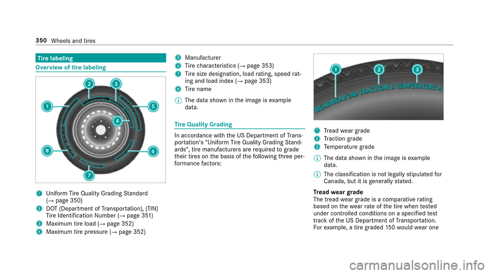
Overview of tire labeling
1Uni form Ti reQuality Grading Standard
(→page 350)
2DOT (Department of Transpor tation), (TIN)
Ti re Identification Number (→page 351)
3Maximum tire load (→page 352)
4Maximum tire pressure (→page 352)
5Manufacturer
6Tire characteristics (→page 353)
7Tire size designation, load rating, speed rat‐
ing and load ind ex(→page 353)
8Tire name
% The da tashown in the image is example
data.
Ti re Quality Grading
In accordance with the US Department of Trans‐
por tation's "Unifo rm TireQuality Grading Stand‐
ards", tire manufacturers are requ ired tograde
th eir tires on the basis of thefo llowing thre e per‐
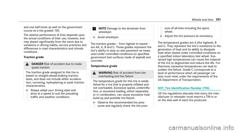
fo rm ance factors:1Tread weargrade
2Traction grade
3Te mp erature grade
% The data shown in the image is example
data.
% The classification is not legally stipulated for
Canada, but it is general lystated.
Tr ead weargrade
The tread wear grade is a comparative rating
based on thewe arrate ofthe tire when tested
under controlled conditions on a specified test
track of the US Department of Transpor tation.
Fo rex ample, a tire graded 150wo uld wear one
350
Wheels and tires
Page 353 of 482
and one-half times aswell on the go vernment
course as a tire graded 100.
The relative per form ance of tires depends upon
th e actual conditions of their use, ho wever,and
may depart significantly from the norm due to
va riations in driving habits, service practices and
dif fere nces in road characteristics and climate
conditions.
Tr action grade
&
DANG ER Risk of accident due toinade‐
qu ate traction
The traction grade assigned tothis tire is
based on stra ight-ahead braking traction
te sts, and does not include either accelera‐
tion, cornering, hydroplaning or peak traction
ch aracteristics.
#Alw ays adapt your drivin gst yle and
drive at a speed tosuit the pr evailing
traf fic and weather conditions.
* NO
TEDama getothe driv etra in from
wheelspin
#Av oid wheelspin.
The traction grades – from highest tolowest –
are AA, A,B and C. Those grades represent the
tire's ability tostop on wet pa vement as meas‐
ured under controlled conditions on specified
go vernment test sur faces made of asphalt and
concr ete.
Te mp erature grade
&
WARNING Risk of accident from tire
ove rheating and tire failure
The temp erature grade forth is tire is es tab‐
lished for a tire that is proper ly inflated and
not overloaded. Excessive speed, underinfla‐
tion, or excessive loading, either separately
or in combination, can cause excessive heat
build-up and possible tire failure.
#Obser vethere commended tire pres‐
sure s and regularly check the tire pres‐
sure of all tires including the spare
wheel.
#Ad just the tire pressure as necessar y.
Thetemp erature grades are A (the highest), B
and C. They represent the tire's resis tance tothe
ge neration of heat and its ability todissipate
heat when tested under controlled conditions on
a specified indoor laboratory test wheel. Sus‐
ta ined high temp eratures can cause the material
of the tire todegenerate and reduce tire life. Fur‐
th ermore, excessive temp eratures can lead to
sudden tire failure. Grade C cor responds toa
le ve l of per form ance which all passenger car
tires must meet under therequ irements of the
US Department of Transpor tation.
DO T,Tire Identification Number (TIN)
US tire regulations stipulate that eve rytire man‐
ufactu rer or retreader must imprint a TIN in or
on the side wall of each tire produced.
Wheels and tires 351