2017 MERCEDES-BENZ CLA tow bar
[x] Cancel search: tow barPage 21 of 318
General notes ................................ 289
Important safety notes .................. 290
Radio type approval for the tire
pressure monitor .......................... .2 92
Restarting ...................................... 291
Warning lamp ................................. 226
Warning message .......................... 291
TIREFIT kit .......................................... 268
Important safety notes .................. 268
Storage location ............................ 266
Tire pressure not reached .............. 269
Tire pressure reached .................... 270
Tires
Aspect ratio (definition) ................. 301
Average weight of the vehicle
occupants (definition) .................... 299
Bar (definition) ............................... 299
Changing a wheel .......................... 301
Characteristics .............................. 299
Checking ........................................ 282
Curb weight (definition) ................. 300
Definition of terms ......................... 299
Direction of rotation ...................... 302
Display message ............................ 209
Distribution of the vehicle occu-
pants (definition) ............................ 301
DOT (Department of Transporta-
tion) (definition) ............................. 299
DOT, Tire Identification Number
(TIN) ............................................... 299
GAWR (Gross Axle Weight Rating)
(definition) ..................................... 300
General notes ................................ 306
GVW (Gross Vehicle Weight) (def-
inition) ........................................... 300
GVWR (Gross Vehicle Weight Rat-
ing) (definition) .............................. 300
Important safety notes .................. 282
Increased vehicle weight due to
optional equipment (definition) ...... 300
Information on driving .................... 282
Kilopascal (kPa) (definiti on) ........... 300
La b
eling (overview) ........................ 296
Load bearing index (definition) ...... 301
Load index ..................................... 298
Load index (definition) ................... 300
M+S tires ....................................... 284 Maximum load on a tire (defini-
tion) ............................................... 300
Maximum loaded vehicle weight
(definition) ..................................... 300
Maximum permissible tire pres-
sure (definition) ............................. 300
Maximum tire load ......................... 298
Maximum tire load (definition) ....... 300
MOExtended tires .......................... 284
Optional equipment weight (defi-
nition) ............................................ 301
PSI (pounds per square inch) (def-
inition) ........................................... 301
Replacing ....................................... 301
Service life ..................................... 283
Sidewall (definition) ....................... 301
Speed rating (definition) ................ 300
Storing ........................................... 302
Structure and characteristics
(definition) ..................................... 299
Summer tires ................................. 284
Temperature .................................. 296
TIN (Tire Identification Number)
(definition) ..................................... 301
Tire bead (definition) ...................... 301
Tire pressure (definition) ................ 301
Tire pressures (recommended) ...... 300
Tire size (data) ............................... 306
Tire size designation, load-bearing
capacity, speed rating .................... 296
Tire tread ....................................... 283
Tire tread (definition) ..................... 301
Total load limit (definition) ............. 301
Traction ......................................... 295
Traction (definition) ....................... 301
Tread wear ..................................... 295
Uniform Tire Quality Grading
Standards ...................................... 295
Uniform Tire Quality Grading
Standards (definition) .................... 300
Wear indicator (definition) ............. 301
Wheel rim (definition) .................... 300
see Fla t ti re
To
p Tether ............................................ 56
Tow-starting
Emergency engine starting ............ 279
Important safety notes .................. 276
Installing the towing eye ................ 277 Index 19
Page 169 of 318
R
if the camera lens is dirty or obstructed
Observe the notes on cleaning
( Y
page 262) R
if the rear of your vehicle is damaged. In this
case, have the camera position and setting
checked at a qualified specialist workshop
The field of vision and other functions of the rear
view camera may be restricted due to additional
accessories on the rear of the vehicle (e.g.
license plate holder, bicycle rack).
Activating/deactivating the rear view
camera X
To activate: make sure that the SmartKey is
in position 2 in the ignition lock.X
Make sure that the Activation by R gear
function is selected in the multimedia system;
see the Digital Operator's Manual. X
Engage reverse gear.
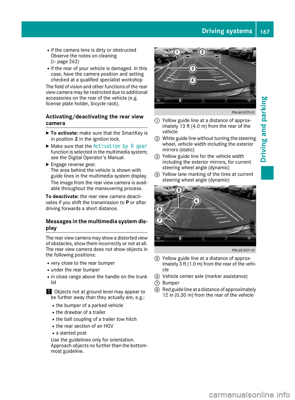
The area behind the vehicle is shown with
guide lines in the multimedia system display.
The image from the rear view camera is avail-
able throughout the maneuvering process.
To deactivate: the rear view camera deacti-
vates if you shift the transmission to P or after
driving forwards a short distance.
Messages in the multimedia system dis-
play The rear view camera may show a distorted view
of obstacles, show them incorrectly or not at all.
The rear view camera does not show objects in
the following positions: R
very close to the rear bumper R
under the rear bumper R
in close range above the handle on the trunk
lid
! Objects not at ground level may appear to
be further away than they actually are, e.g.: R
the bumper of a parked vehicle R
the drawbar of a trailer R
the ball coupling of a trailer tow hitch R
the rear section of an HGV R
a slanted post
Use the guidelines only for orientation.
Approach objects no further than the bottom-
most guideline. �C
Yellow guide line at a distance of approx-
imately 13 ft (4.0 m) from the rear of the
vehicle �D
White guide line without turning the steering
wheel, vehicle width including the exterior
mirrors (static) �
Page 272 of 318
Tire pressure reached
G WARNING
A tire temporarily sealed with tire sealant
impairs the driving characteristics and is not
suitable for higher speeds. There is a risk of
accident.
You should therefore adapt your driving style
accordingly and drive carefully. Do not exceed
the specified maximum speed with a tire that
has been repaired using tire sealant.
The maximum permissible speed for a tire
sealed with tire sealant is 50 mph (80 km/h).
The upper part of the TIREFIT sticker must be
affixed to the instrument cluster in the driver's
field of vision.
If a tire pressure of 200 kPa (2.0 bar/29 psi) has
been attained after ten minutes: X
Switch off the tire inflation compressor. X
Unscrew the filler hose from the valve of the
faulty tire.
Note that tire sealant may escape when you
unscrew the filler hose. X
Stow the tire sealant bottle and the tire infla-
tion compressor. X
Pull away immediately .X
Stop after driving for approximately ten
minutes and check the tire pressure with the
tire inflation compressor.
The tire pressure must now be at least
130 kPa (1.3 bar/19 psi).
G WARNING
If the required tire pressure is not reached
after driving for a short period, the tire is too
badly damaged. The tire sealant cannot repair
the tire in this instance. Damaged tires and a
tire pressure that is too low can significantly
impair the vehicle's braking and driving char-
acteristics. There is a risk of accident.
Do not continue driving. Contact a qualified
specialist workshop.
i In cases such as the one mentioned above,
contact an authorized Mercedes-Benz Cen-
ter. Or call 1-800-FOR-MERCedes (in the
USA) or 1-800-387-0100 (in Canada). X
Correct the tire pressure if it is still at least
130 kPa (1.3 bar/19 psi). See the Tire and
Loading Information placard on the driver's
side B-pillar or the tire pressure table in the
fuel filler flap for values. X
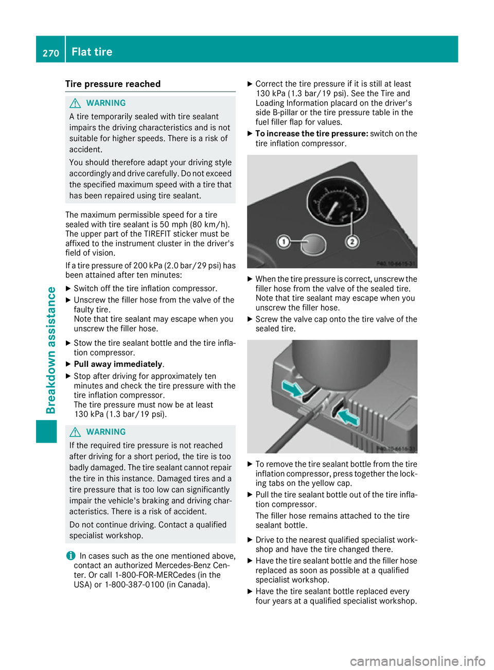
To increase the tire pressure: switch on the
tire inflation compressor.
X
When the tire pressure is correct, unscrew the
filler hose from the valve of the sealed tire.
Note that tire sealant may escape when you
unscrew the filler hose. X
Screw the valve cap onto the tire valve of the
sealed tire.
X
To remove the tire sealant bottle from the tire
inflation compressor, press together the lock-
ing tabs on the yellow cap. X
Pull the tire sealant bottle out of the tire infla-
tion compressor.
The filler hose remains attached to the tire
sealant bottle. X
Drive to the nearest qualified specialist work-
shop and have the tire changed there. X
Have the tire sealant bottle and the filler hose
replaced as soon as possible at a qualified
specialist workshop. X
Have the tire sealant bottle replaced every
four years at a qualified specialist workshop.270
Flat tire
Breakdown assistance
Page 278 of 318
i Jumper cables and further information regarding jump-starting can be obtained at any qualified
specialist workshop.
Towing and tow-starting
Important safety notes
G WARNING
Functions relevant to safety are restricted or
no longer available if: R
the engine is not running. R
the brake system or the power steering is
malfunctioning. R
there is a malfunction in the voltage supply
or the vehicle's electrical system.
If your vehicle is being towed, much more
force may be necessary to steer or brake.
There is a risk of an accident.
In such cases, use a tow bar. Before towing,
make sure that the steering moves freely.
G WARNING
You can no longer steer the vehicle if the
steering wheel lock has been engaged. There
is a risk of an accident.
Always switch off the ignition when towing the
vehicle with a tow cable or a tow bar.
G WARNING
When towing or tow-starting another vehicle
and its weight is greater than the permissible
gross weight of your vehicle, the: R
the towing eye could detach itself R
the vehicle/trailer combination could roll-
over.
There is a risk of an accident.
When towing or tow-starting another vehicle,
its weight should not be greater than the per-
missible gross weight of your vehicle.
Details on the permissible gross vehicle weight
of your vehicle can be found on the vehicle iden-
tification plate ( Y
page 308).
! When Active Brake Assist, Distance Pilot
DISTRONIC or the HOLD function is activated, the vehicle brakes automatically in certain
situations.
To avoid damage to the vehicle, deactivate
these systems in the following or similar sit-
uations: R
when towing the vehicle R
in the car wash
! Make sure that the electric parking brake is
released. If the electric parking brake is faulty,
visit a qualified specialist workshop.
! Only secure the tow rope or tow bar at the
towing eyes. Otherwise, the vehicle could be
damaged.
! Do not use the towing eyes for recovery pur-
poses as this could damage the vehicle. If in
doubt, recover the vehicle with a crane.
! When towing, pull away slowly and
smoothly. If the tractive power is too high, the
vehicles could be damaged.
! The vehicle can be towed a maximum of
30 miles (50km). The towing speed of 30 mph
(50km/h) must not be exceeded.
If the vehicle has to be towed more than
30 miles (50km), the front axle must be raised
or the entire vehicle raised and transported.
! Do not tow with sling-type equipment. This
could damage the vehicle.
! When towing vehicles with KEYLESS-GO,
use the key instead of the Start/Stop button.
Otherwise, the automatic transmission may
shift to position P when the driver's or front-
passenger door are opened, which could lead
to damage to the transmission.
! Vehicles with automatic transmission must
not be started by tow-starting. This could oth-
erwise damage the transmission.
It is better to have the vehicle transported than
to have it towed away.
If the vehicle can no longer be driven because of
an accident or breakdown, you have the follow-
ing options: R
transporting the vehicle276
Towing and tow-starting
Breakdown assistance
Page 279 of 318
As a rule, you should have the vehicle trans-
ported. R
towing the vehicle with a tow rope or tow bar
Only tow the vehicle in exceptional cases.
The battery must be connected and charged.
Otherwise, you: R
cannot turn the SmartKey to position 2 in the
ignition lock R
cannot release the electric parking brake R
cannot move the transmission to position N
The function of the electric parking brake and
the parking lock is dependent on the on-board
voltage.
If the on-board voltage is low or if there is a sys-
tem malfunction: R
the electric parking brake may not be applied
in certain circumstances, or R
the transmission may not be shifted to P
Switch off non-essential consumers, e.g. the
radio.
Disarm the automatic locking feature before the
vehicle is towed ( Y
page 184). You could other-
wise be locked out when pushing or towing the
vehicle.
Installing/removing the towing eye
Installing the towing eye
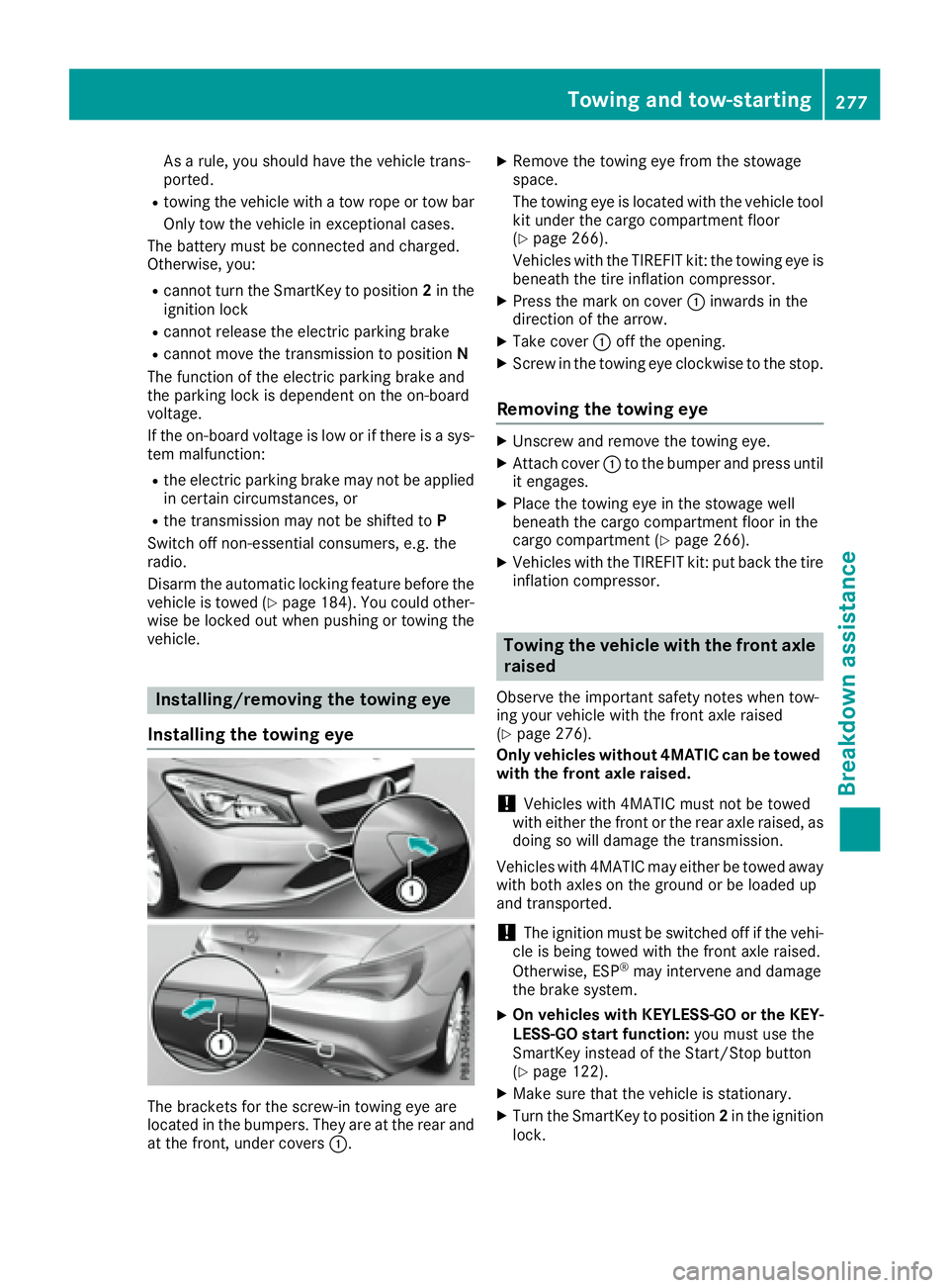
The brackets for the screw-in towing eye are
located in the bumpers. They are at the rear and
at the front, under covers �C . X
Remove the towing eye from the stowage
space.
The towing eye is located with the vehicle tool
kit under the cargo compartment floor
( Y
page 266).
Vehicles with the TIREFIT kit: the towing eye is
beneath the tire inflation compressor. X
Press the mark on cover �C inwards in the
direction of the arrow. X
Take cover �C off the opening. X
Screw in the towing eye clockwise to the stop.
Removing the towing eye X
Unscrew and remove the towing eye. X
Attach cover �C to the bumper and press until
it engages. X
Place the towing eye in the stowage well
beneath the cargo compartment floor in the
cargo compartment ( Y
page 266).X
Vehicles with the TIREFIT kit: put back the tire
inflation compressor.
Towing the vehicle with the front axle
raised Observe the important safety notes when tow-
ing your vehicle with the front axle raised
( Y
page 276).
Only vehicles without 4MATIC can be towed
with the front axle raised.
! Vehicles with 4MATIC must not be towed
with either the front or the rear axle raised, as
doing so will damage the transmission.
Vehicles with 4MATIC may either be towed away
with both axles on the ground or be loaded up
and transported.
! The ignition must be switched off if the vehi-
cle is being towed with the front axle raised.
Otherwise, ESP ®
may intervene and damage
the brake system. X
On vehicles with KEYLESS-GO or the KEY-
LESS-GO start function: you must use the
SmartKey instead of the Start/Stop button
( Y
page 122). X
Make sure that the vehicle is stationary. X
Turn the SmartKey to position 2 in the ignition
lock.Towing and tow-starting 277
Breakdo wn assis tance Z