2017 MERCEDES-BENZ CLA-Class radio
[x] Cancel search: radioPage 164 of 318

iParking Assist PARKTRONIC is automati-
cally activated when you turn the SmartKey to
position 2in the ignition lock.
Problems with Parking Assist PARKTRONIC
ProblemPossible causes/consequences and MSolutions
Only the red segments in
the Parking Assist
PARKTRONIC warning
displays are lit. You also
hear a warning tone for
approximately two sec-
onds.
Parking Assist
PARKTRONIC is then
deactivated and the indi-
cator lamp on the
PARKTRONIC button
lights up.Parking Assist PARKTRONIC has malfunctioned and has been deacti-
vated.
XIf problems persist, have Parking Assist PARKTRONIC checked at a
qualified specialist workshop.
Only the red segments in
the Parking Assist
PARKTRONIC warning
displays are lit. Parking
Assist PARKTRONIC is
then deactivated.The Parking Assist PARKTRONIC sensors are dirty or there is inter-
ference.
XClean the Parking Assist PARKTRONIC sensors (Ypage 262).
XSwitch the ignition back on.
The problem may be caused by an external source of radio or ultra-
sound waves.
XCheck to see if Parking Assist PARKTRONIC works at a different
location.
Parking Pilot
General notes
Parking Pilot is an electronic parking aid with
ultrasound. It measures the road on both sides
of the vehicle. A parking symbol indicates a suit-
able parking space. Active steering intervention
and brake application can assist you during
parking and when exiting a parking space. Park-
ing Assist PARKTRONIC is also available
(
Ypage 160).
Important safety notes
Parking Pilot is only an aid. It is not a replace-
ment for your attention to your immediate sur-
roundings. You are always responsible for safe
maneuvering, parking and exiting a parking
space. Make sure that no persons, animals or
objects are in the maneuvering range. When Parking Assist PARKTRONIC is deactiva-
ted, Parking Pilot is also unavailable.
GWARNING
While parking or pulling out of a parking
space, the vehicle swings out and can drive
onto areas of the oncoming lane. This could
result in a collision with another road user.
There is a risk of an accident.
Pay attention to other road users. Stop the
vehicle if necessary or cancel the Parking Pilot
parking procedure.
!If unavoidable, you should drive over obsta-
cles such as curbs slowly and not at a sharp
angle. Otherwise, you may damage the
wheels or tires.
162Driving systems
Driving and parking
Page 182 of 318

Audio menu
Selecting a radio station
:Active station list
;Station frequency wit hmemory position
The multifunction display shows station ;with
station frequency or station name. The preset
position is only displayed alon gwit hstation ;if
this has been stored.
XSwitc hon th emultimedia system and select
Radio (see th eseparat eoperating instruc-
tions).
XPress th e= or; buttonon th esteering
whee lto select th eAudiomenu.
XTo select apreset list or station list :press
and briefl yhold th e9 or: buttonuntil
th epreset list or station list in th edesired
frequency range is shown.
XTo select astation: brieflypress 9
or :.
iSIRIUS XM satellit eradi ofunction slik e a
normal radio.
You can fin dfurther information on operation
in th e"Satellit eradio" section of th eseparat e
multimedia system operating instructions.
Operating an audio player oraudio
media
:Curren ttitl e Audio dat
afrom various audio device sor media
can be played ,depending on th eequipmen t
installed in th evehicle.
XSwitc hon th emultimedia system and then
audio CD or MP3 mod e(see th eseparat e
operating instructions).
XPress th e= or; buttonon th esteering
whee lto select th eAudiomenu.
XTo select th enext/previou strack :briefl y
press th e9 or: button.
XTo select atrack from th etrack list (rapid
scrolling): press and hold th e9 or:
butto nuntil desired track appears.
If you press and hold 9or:, therapi d
scrollin gspee dis increased. Not all audio
drives or dat acarriers support this function .
If track information is store don th eaudio device
or medium, th emultifunction display will sho w
th enumber and titl eof th etrack .
Video DVD operation
You can only operate DV Dvideos in th eAudiomen uin vehicles wit hCOMAND .
XSwitchon COMAND and select video DV D
(see th eseparat eoperating instructions).
XPress th e= or; buttonon th esteering
whee lto select th eAudiomenu.
XTo select th enext or previou sscene:
briefl ypress th e9 or: button.
XTo select ascene from th escene list
(rapid scrolling): press and hold the9
or : buttonuntil desired scen e:
appears.
Telephone menu
Introd uction
GWARNIN G
If you operate information systems and com-
munication equipmen tintegrate din th evehi-
180Menus and submenus
On-board computer and displays
Page 229 of 318

General notes
The multimedia system section in this Opera-
tor's Manual describes the basic principles for
operation. More information can be found in theDigital Operator's Manual.
Important safety notes
GWARNING
If you operate information systems and com-
munication equipment integrated in the vehi-
cle while driving, you will be distracted from
traffic conditions. You could also lose control
of the vehicle. There is a risk of an accident.
Only operate the equipment when the traffic
situation permits. If you are not sure that this
is possible, park the vehicle paying attention
to traffic conditions and operate the equip-
ment when the vehicle is stationary.
You must observe the legal requirements for the
country in which you are currently driving when
operating the multimedia system.
The multimedia system calculates the route to
the destination without taking the following into
account, for example:
Rtraffic lights
Rstop and yield signs
Rparking or stopping restrictions
Rroad narrowing
Rother road and traffic rules and regulations
The multimedia system may give incorrect nav-
igation recommendations if the actual street/
traffic situation does not correspond with the
digital map's data.
For example:
Ra diverted route
Rthe road layout or the direction of a one-way
street has been changed
For this reason, you must always observe road
and traffic rules and regulations during your
journey. Road and traffic rules and regulations
always have priority over multimedia system
driving recommendations.
Navigation announcements are intended to
direct you while driving without diverting your
attention from the road and driving. Please always use this feature instead of con-
sulting the map display for directions. Looking
at the icons or map display can distract you from
traffic conditions and driving, and increase the
risk of an accident.
This equipment complies with FCC radiation
exposure limits set forth for uncontrolled equip-
ment and meets the FCC radio frequency (RF)
Exposure Guidelines in Supplement C to OET65.
This equipment has very low levels of RF energy
that is deemed to comply without maximum
permissive exposure evaluation (MPE). How-
ever, it is recommended
to insta
ll it at a distance
of at least 8 inches (approx. 20 cm) between the
radiation source and a person's body (not
including limbs such as hands, wrists, feet and
legs).
GWARNING
Modifications to electronic components, their software as well as wiring can impair their
function and/or the function of other net-
worked components. In particular, systems
relevant to safety could also be affected. As a
result, these may no longer function as inten-
ded and/or jeopardize the operating safety of
the vehicle. There is an increased risk of an
accident and injury.
Never tamper with the wiring as well as elec-
tronic components or their software. You
should have all work to electrical and elec-
tronic equipment carried out at a qualified
specialist workshop.
If you make any changes to the vehicle elec-
tronics, the general operating permit is ren-
dered invalid.
Function restrictions
For safety reasons, some functions are restric-
ted or unavailable while the vehicle is in motion.
You will notice this, for example, because either
you will not be able to select certain menu items
or a message will appear to this effect.
Function restrictions227
Multimedia system
Z
Page 230 of 318

Operating system
Overview
General notes
!Do not use the space in front of the display
for storage. Objects placed here could dam-
age the display or impair its function. Avoid
any direct contact with the display surface.
Pressure on the display surface may result in
impairments to the display, which could be
irreversible.
Wearing polarized sunglasses may impair your
ability to read the display.
The display has an automatic temperature-con-
trolled switch-off feature. The brightness is
automatically reduced if the temperature is too
high. The display may temporarily switch off
completely.
Cleaning instructions
!Do not touch the display. The display has a
very sensitive high-gloss surface; there is a
risk of scratching. If you have to clean the
screen, however, use a mild cleaning agent
and a soft, lint-free cloth.
The display must be switched off and have
cooled down before you start cleaning. Do not
apply pressure to the display surface when
cleaning it, as this could cause irreversible dam-
age to the display.
Switching the multimedia system
on/off
XPress the qcontrol knob.
Adjusting the volume
XTurn the qcontrol knob.
The volume is adjusted:
Rfor the currently selected media source
Rduring traffic or navigation announcements
Rin hands-free mode during a phone call
Switching the sound on or off
XPress the 8button on the control panel.
If the audio output is switched off, the status
line will show the 8symbol. If you switch the media source or set the volume, the sound
is automatically switched on.
iNavigation announcements will be heard
even if the sound is muted.
Functions
The multimedia system has the following func-
tions:
RRadio mode
RMedia mode with media search
RSound systems
RNavigation system
COMAND: navigation via the hard drive
Audio 20: navigation via SD card
RCommunication functions
RSIRIUS Weather (COMAND)
RVehicle functions with system settings
RFavorites functions
Controller
The controller in the center console lets you:
Rselect menu items on the display
Renter characters
Rselect a destination on the map
Rsave entries
The controller can be:
Rturned 3
Rslid left or right 1
Rslid forwards or back 4
Rslid diagonally2
Rpressed briefly or pressed and held 7
Back button
You can use the%button to exit a menu or to
call up the basic display of the current operating
mode.
XTo exit the menu: briefly press the%
button.
The multimedia system changes to the next
higher menu level in the current operating
mode.
XTo call up the basic display: press the%
button for longer than two seconds.
The multimedia system changes to the basic
display of the current operating mode.
228Operating system
Multimedia system
Page 252 of 318

XTo start program mode:press and hold one
of buttons ;to? on the integrated garage
door opener.
The garage door opener is now in program
mode. After a short time, indicator lamp :
lights up yellow.
Indicator lamp :lights up yellow as soon as
button ;,=or? is stored for the first time.
If the selected button has already been pro-
gramed, indicator lamp :will only light up
yellow after ten seconds have elapsed.
XRelease button ;,=or?. Indicator
lamp :flashes yellow.
XTo program the remote control: point
garage door remote control Atowards but-
tons ;to? on the rear-view mirror at a dis-
tance of 2 to 8 in (5 to 20 cm).
XPress and hold button Bon remote control
A until indicator lamp :lights up green.
When indicator lamp :lights up green: pro-
gramming is finished.
When indicator lamp :flashes green: pro-
gramming was successful. The next step is to synchronize the rolling code (
Ypage 250).
XRelease button Bon remote control Afor
the garage door drive system.
If indicator lamp :lights up red: repeat the
programing procedure for the corresponding
button on the rear-view mirror. When doing
so, vary the distance between remote contro l
A a
nd the rear-view mirror.
The required distance between remote con-
trol Aand the integrated garage door opener
depends on the garage door drive system.
Several attempts might be necessary. You
should test every position for at least
25 seconds before trying another position.
Synchronizing the rolling code
Pay attention to the "Important safety notes"
(Ypage 249).
If the garage door system uses a rolling code,
you will also have to synchronize the garage
door system with the integrated garage door
opener in the rear-view mirror. To do this you will
need to use the programming button on the door
drive control panel. The programming button
may be located in different places depending on
the manufacturer. It is usually located on the
door drive unit on the garage ceiling.
Familiarize yourself with the garage door drive
operating instructions, e.g. under "Program- ming additional remote controls", before carry-
ing out the following steps.
Your vehicle must be within reach of the garage
door or gate opener drive. Make sure that nei-
ther your vehicle nor any persons/objects are
present within the sweep of the door or gate.
XTurn the SmartKey to position
2in the ignition
lock (Ypage 121).
XGet out of the vehicle.
XPress the programming button on the door
drive unit.
Usually, you now have 30 seconds to initiate
the next step.
XGet into the vehicle.
XPress previously programed button ;,=
or ? on the integrated garage door opener
repeatedly and in quick succession until the
door closes.
The rolling code synchronization is then com- plete.
Notes on programming the remote con-
trol
Canadian radio frequency laws require a "break"
(or interruption) of the transmission signals
after broadcasting for a few seconds. Therefore,
these signals may not last long enough for the
integrated garage door opener. The signal is not
detected during programming. Comparable withCanadian law, some U.S. garage door openers
also feature a "break".
Proceed as follows:
Rif you live in Canada
Rif you have difficulties programming the
garage door opener (regardless of where you
live) as you follow the programming steps.
XPress and hold one of buttons ;to? on the
integrated garage door opener.
After a short time, indicator lamp :lights up
yellow.
XRelease the button.
Indicator lamp :flashes yell ow.
XPress button Bof garage door remote con-
trol Afor two seconds, then release it for two
seconds.
XPress button Bagain for two seconds.
XRepeat this sequence on button Bof remote
control Auntil indicator lamp :lights up
green.
When indicator lamp :lights up green: pro-
gramming is finished.
250Features
Stowag ean d features
Page 279 of 318
As a rule, you should have the vehicle trans-
ported.
Rtowing the vehicle with a tow rope or tow bar
Only tow the vehicle in exceptional cases.
The battery must be connected and charged.
Otherwise, you:
Rcannot turn the SmartKey to position 2in the
ignition lock
Rcannot release the electric parking brake
Rcannot move the transmission to position N
The function of the electric parking brake and
the parking lock is dependent on the on-board
voltage.
If the on-board voltage is low or if there is a sys-
tem malfunction:
Rthe electric parking brake may not be applied
in certain circumstances, or
Rthe transmission may not be shifted to P
Switch off non-essential consumers, e.g. the
radio.
Disarm the automatic locking feature before the
vehicle is towed (
Ypage 184). You could other-
wise be locked out when pushing or towing the
vehicle.
Installing/removing the towing eye
Installing the towing eye
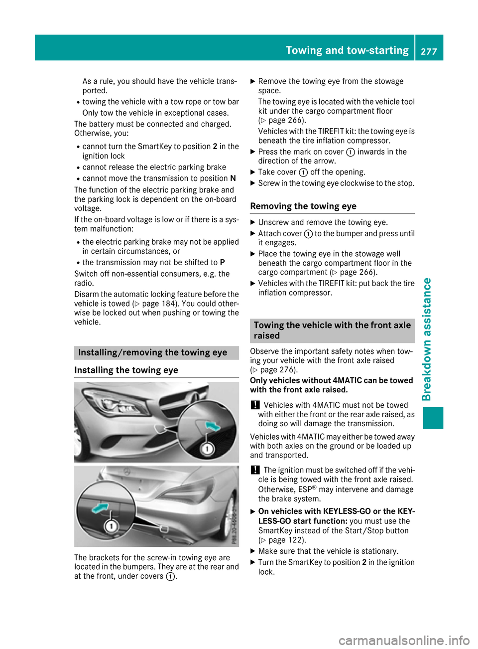
The brackets for the screw-in towing eye are
located in the bumpers. They are at the rear and
at the front, under covers :.
XRemove the towing eye from the stowage
space.
The towing eye is located with the vehicle tool
kit under the cargo compartment floor
(
Ypage 266).
Vehicles with the TIREFIT kit: the towing eye is beneath the tire inflation compressor.
XPress the mark on cover :inwards in the
direction of the arrow.
XTake cover :off the opening.
XScrew in the towing eye clockwise to the stop.
Removing the towing eye
XUnscrew and remove the towing eye.
XAttach cover :to the bumper and press until
it engages.
XPlace the towing eye in the stowage well
beneath the cargo compartment floor in the
cargo compartment (
Ypage 266).
XVehicles with the TIREFIT kit: put back the tire inflation compressor.
Towing the vehicle with the front axle
raised
Observe the important safety notes when tow-
ing your vehicle with the front axle raised
(
Ypage 276).
Only vehicles without 4MATIC can be towed
with the front axle raised.
!Vehicles with 4MATIC must not be towed
with either the front or the rear axle raised, as doing so will damage the transmission.
Vehicles with 4MATIC may either be towed away
with both axles on the ground or be loaded up
and transported.
!The ignition must be switched off if the vehi-
cle is being towed with the front axle raised.
Otherwise, ESP
®may intervene and damage
the brake system.
XOn vehicles with KEYLESS-GO or the KEY-
LESS-GO start function: you must use the
SmartKey instead of the Start/Stop button
(
Ypage 122).
XMake sure that the vehicle is stationary.
XTurn the SmartKey to position 2in the ignition
lock.
Towing and tow-starting277
Breakdo wn assis tance
Z
Page 293 of 318

the information on display messages
(Ypage 209).
It may take up to ten minutes for a malfunction of the tire pressure monitor to be indicated. A
malfunction will be indicated by the tire pres-
sure warning lamp flashing for approximately
one minute and then remaining lit. When the
malfunction has been rectified, the tire pressure
warning lamp goes out after a few minutes of
driving.
The tire pressure values indicated by the on-
board computer may differ from those meas-
ured at a gas station with a pressure gauge. The
tire pressures shown by the on-board computer
refer to those measured at sea level. At high
altitudes, the tire pressure values indicated by a
pressure gauge are higher than those shown by the on-board computer. In this case, do not
reduce the tire pressures.
The operation of the tire pressure monitor can
be affected by interference from radio transmit-
ting equipment (e.g. radio headphones, two-way
radios) that may be being operated in or near the vehicle.
Checking the tire pressure electroni-
cally
XMake sure that the SmartKey is in position 2
in the ignition lock (Ypage 121).
XPress =or; on the steering wheel to
select the Serv.menu.
XPress the9or: button to select
Tire Pressure.
XPress the abutton.
The current tire pressure of each tire is shown
in the multifunction display.
If the vehicle was parked for longer than
20 minute s,the Tire pressure will be
displayed after driving a few minutesmessage is shown.
After a teach-in process, the tire pressure mon-
itor automatically detects new wheels or new
sensors. As long as a clear allocation of the tire
pressure value to the individual wheels is not
possible, the Tire
PressureMonitorActivemessage is shown instead of the tire pressure
display. The tire pressures are already being
monitored.
Tire pressure monitor warning mes-
sages
If the tire pressure monitor detects a pressure
loss in one or more tires, a warning message is
shown in the multifunction display. The yellow
tire pressure warning lamp then lights up.
RIf thePlease Correct Tire Pressuremessage appears in the multifunction display,
the tire pressure in at least one tire is too low.
The tire pressure must be corrected when the
opportunity arises.
RIf the Check Tire Pressuremessage
appears in the multifunction display, the tire
pressure in one or more tires has dropped
significantly. The tires must be checked.
RIf the TirePressureWarningTireFail‐uremessage appears, the tire pressure in one
or more tires has dropped suddenly. The tires
must be checked.
Observe the instructions and safety notes in the
display messages in the "Tires" section
(
Ypage 209).
If the wheel positions on the vehicle are rotated,
the tire pressures may be displayed for the
wrong positions for a short time. This is rectified after a few minutes of driving, and the tire pres-
sures are displayed for the correct positions.
Restarting the tire pressure monitor
When you restart the tire pressure monitor, all
existing warning messages are deleted and the
warning lamps go out. The monitor uses the cur-
rently set tire pressures as the reference valuesfor monitoring. In most cases, the tire pressure
monitor will automatically detect the new refer-
ence values after you have changed the tire
pressure. However, you can also set reference
values manually as described here. The tire
pressure monitor then monitors the new tire
pressure values.
XSet the tire pressure to the value recommen-
ded for the corresponding driving situation on
the Tire and Loading Information placard on
the driver's side B-pillar (
Ypage 285).
You can find more tire pressure values for
various operating conditions in the tire pres-
sure table inside the fuel filler flap
(
Ypage 138).
XMake sure that the tire pressure is correct on
all four wheels.
Tire pressure291
Wheels and tires
Z
Page 294 of 318

XMake sure that the SmartKey is in position2
in the ignition lock (Ypage 121).
XPress =or; on the steering wheel to
select the Serv.menu.
XPress the9or: button to select
Tire Pressure.
XPress the abutton.
The multifunction display shows the current
tire pressure for each tire or the Tire pres‐
surewillbedisplayedafterdrivinga few minutesmessage.
XPress the:button.
The multifunction display shows the Use
Current Pressures as New ReferenceValuesmessage.
If you wish to confirm the restart:
XPress the abutton.
The TirePress.MonitorRestartedmes-
sage appears in the multifunction display.
After driving for a few minutes, the system
checks whether the current tire pressures are within the specified range. The new tire pres-
sures are then accepted as reference values
and monitored.
If you wish to cancel the restart:
XPress the %button.
The tire pressure values stored at the last
restart will continue to be monitored.
Radio type approval for the tire pres-
sure monitor
CountryRadio type approval number
USAFCC ID: MRXMW2433A
FCC ID: MRXGG4
FCC ID: MRXMC34MA4
CanadaIC: 2546A-MW2433A
IC: 2546A-GG4
IC: 2546A-MC34MA4
Loading the vehicle
Instruction labels for tires and loads
GWARNING
Overloaded tires can overheat, causing a
blowout. Overloaded tires can also impair the
steering and driving characteristics and lead
to brake failure. There is a risk of accident.
Observe the load rating of the tires. The load
rating must be at least half of the GAWR of
your vehicle. Never overload the tires by
exceeding the maximum load.
Two instruction labels on your vehicle show the
maximum possible load.
(1) The Tire and Loading Information placard is on the B-pillar on the driver's side. The Tireand Loading Information placard shows the
maximum permissible number of occu-
pants and the maximum permissible vehicle
load. It also contains details of the tire sizes
and corresponding pressures for tires
mounted at the factory.
(2) The vehicle identification plate is on the B- pillar on the driver's side. The vehicle iden-
tification plate informs you of the gross
vehicle weight rating. It is made up of the
vehicle weight, all vehicle occupants, the
fuel and the cargo. You can also find infor-
mation about the maximum gross axle
weight rating on the front and rear axle.
The maximum gross axle weight rating is
the maximum weight that can be carried by
one axle (front or rear axle). Never exceed
the maximum load or the maximum gross
axle weight rating for the front or rear axle.
:B-pillar, driver's side
292Loading the vehicle
Wheels and tires