Page 325 of 470
Maintenance
67
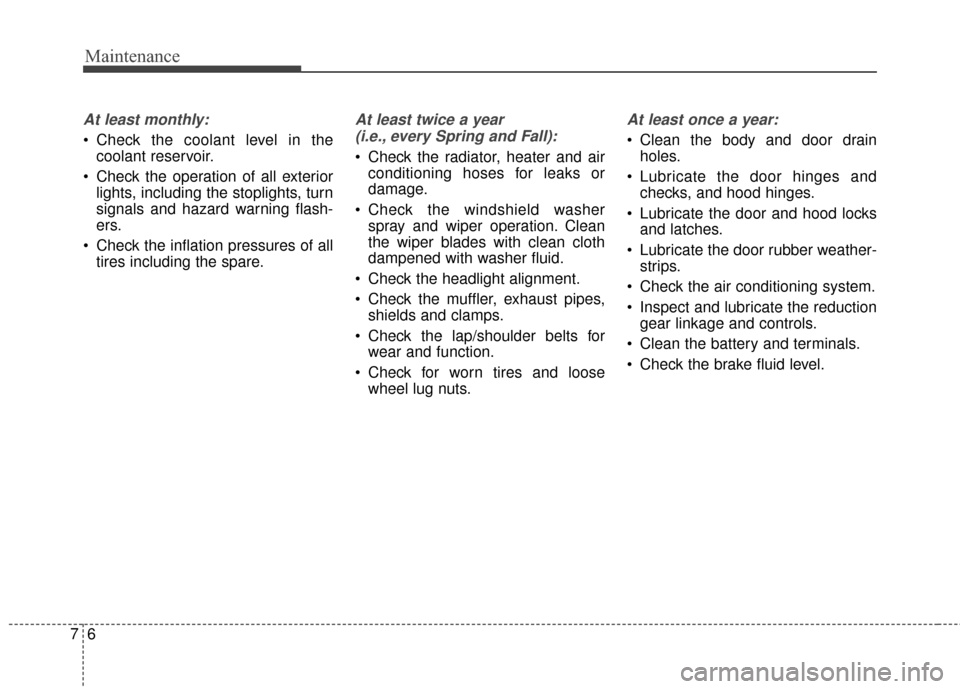
At least monthly:
Check the coolant level in thecoolant reservoir.
Check the operation of all exterior lights, including the stoplights, turn
signals and hazard warning flash-
ers.
Check the inflation pressures of all tires including the spare.
At least twice a year
(i.e., every Spring and Fall):
Check the radiator, heater and air conditioning hoses for leaks or
damage.
Check the windshield washer spray and wiper operation. Clean
the wiper blades with clean cloth
dampened with washer fluid.
Check the headlight alignment.
Check the muffler, exhaust pipes, shields and clamps.
Check the lap/shoulder belts for wear and function.
Check for worn tires and loose wheel lug nuts.
At least once a year:
Clean the body and door drainholes.
Lubricate the door hinges and checks, and hood hinges.
Lubricate the door and hood locks and latches.
Lubricate the door rubber weather- strips.
Check the air conditioning system.
Inspect and lubricate the reduction gear linkage and controls.
Clean the battery and terminals.
Check the brake fluid level.
Page 340 of 470

721
Maintenance
Check the condition and connections
of all cooling system hoses and
heater hoses. Replace any swollen
or deteriorated hoses.
The coolant level should be filled
between F and L marks on the side
of the coolant reservoir when the
motor room is cool.
If the coolant level is low, add enough
specified coolant to provide protec-
tion against freezing and corrosion.
Bring the level to F, but do not over-
fill. If frequent additions are required,
see an authorized Kia dealer for a
cooling system inspection.
Recommended coolant
When adding coolant, use onlydeionized water or soft water for
your vehicle and never mix hard
water in the coolant filled at the fac-
tory. An improper coolant mixture
can result in serious malfunction or
damage.
DO NOT USE alcohol or methanol coolant or mix them with the spec-
ified coolant.
Do not use a solution that contains more than 60% antifreeze or less
than 35% antifreeze, which would
reduce the effectiveness of the
solution.
The cooling circuit of a vehicle equipped with a heat pump system
may freeze in extremely low tem-
perature when the concentration of
the antifreezing liquid is below
45%.
OPSE074002
WARNING- Cooling fan
Use caution when
working near the
blade of the cooling
fan. The electric
motor (cooling fan) is
controlled by coolant tempera-
ture, refrigerant pressure and
vehicle speed. it may some-
times operate even when the
vehicle is not running.
Page 372 of 470

753
Maintenance
Instrument panel (Driver’s side fuse panel)
Fuse Name Fuse ratingCircuit Protected
POWER OUTLET 2 20A Front Power Outlet
ACC 10A BCM, Mood Lamp Module, A/V & Navigation Head Unit, Smart Key Control Module, Power Outside Mirror
Switch, E/R Junction Block (Power Outlet Relay)
POWER OUTLET 1 20A Rear Power Outlet DRL 10A BCM
MODULE 6 7.5A Front Seat Warmer Module, Driver Air Ventilation Seat Control Module
WIPER FRT 1 25A E/R Junction Block (Front Wiper Low Relay) WIPER RR 15A Rear Wiper Motor, Multifunction Switch
MODULE 5 7.5A BCM, Smart Key Control Module
WIPER FRT 2 10A BCM, Multifunction Switch, PCB Block (Front Wiper High Relay)
HEATED STEERING 15A Clock Spring (Steering Wheel Heated) A/CON 7.5A A/C Control Module, Heater Assembly (Cluster Ionizer)
HEATED MIRROR 10A A/C Control Module, Driver/Passenger Power Outside Mirror, Rear Defogger TAIL GATE OPEN 15A Tail Gate Open Relay S/HEATER FRT 20A Front Seat Warmer Module, Driver Air Ventilation Seat Control Module DR LOCK 20A Door Lock Relay, Door Unlock Relay, Two Turn Unlock Relay
A/BAG IND 7.5A Instrument Cluster
AIR BAG 15A SRS Control Module
MODULE 4 10A Electro Chromic Mirror, Front Seat Warmer Module, Driver Air Ventilation Seat Control Module
STOP LAMP 15A Stop Signal Electronic Module
MODULE 7 10A Sport Mode Switch, ICM Relay Box
S/HEATER RR 20A Rear Seat Warmer Module
P/WINDOW RH 25A Power Window RH Relay P/WINDOW LH 25A Power Window LH Relay, Driver Safety Power Window Module
Page 375 of 470
Maintenance
56
7
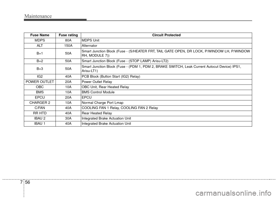
Fuse Name Fuse rating Circuit Protected
MDPS 80A MDPS Unit
ALT 150A Alternator
B+1 50A Smart Junction Block (Fuse - (S/HEATER FRT, TAIL GATE OPEN, DR LOCK, P/WINDOW LH, P/WINDOW
RH, MODULE 7))
B+2 50A Smart Junction Block (Fuse - (STOP LAMP) Arisu-LT2)
B+3 50A Smart Junction Block (Fuse - (PDM 1, PDM 2, BRAKE SWITCH, Leak Current Autocut Device) IPS1,
Arisu-LT1)
IG2 40A PCB Block (Button Start (IG2) Relay)
POWER OUTLET 20A Power Outlet Relay OBC 10A OBC Unit, Rear Heated Relay
BMS 10A BMS Control Module
EPCU 20A EPCU
CHARGER 2 10A Normal Charge Port Lmap C/FAN 40A COOLING FAN 1 Relay, COOLING FAN 2 Relay
RR HTD 40A Rear Heated Relay IBAU 2 30A Integrated Brake Actuation Unit
IBAU 1 40A Integrated Brake Actuation Unit
Page 376 of 470
757
Maintenance
Fuse Name Fuse ratingCircuit Protected
IG1 40A Button Start (ACC) Relay, Button Start (IG1) Relay
BLOWER 40A Blower Relay IG3 1 30A IG3 #1/#2/#3/#4/#5 Relay
EPB 1 30A Electronic Parking Brake Module
EPB 2 30A Electronic Parking Brake Module
IG3 2 10A Blower Relay, A/C Control Module, A/C Compressor, E/R Junction Block (Cooling Fan 1/2 Relay), Heater
Assembly (PTC Heater)
CHARGER 1 10A OBC Unit, BMS Control Module EWP 10A Electronic Water Pump
IG3 3 15A EPCU, Transaxle Range Switch, A/V & Navigation Head Unit, Instrument Cluster
HORN 15A Horn Relay
B/UP LAMP 10A Transaxle Range Switch, EPCU
BATTERY C/FAN 25A Battery C/FAN Relay
No. Relay Name Type
E41 Power Outlet Relay PLUG MICRO
E42 C/FAN 1 Relay PLUG MICRO
E43 RR HTD Relay PLUG MICRO
E44 C/FAN 2 Relay PLUG MINI
Page 414 of 470

4
High Voltage Junction Block: Supplies power from the high voltage bat-
tery to the inverter, LDC, air-conditioner compressor, and PTC heater.
On-Board Charger (OBC): External device (low speed) to charge the high
voltage battery.
Inverter: Transforms direct current into alternating current to supply power
to the motor, and transforms alternating current into direct current to
charge the high voltage battery.
LDC: Transforms power from the high voltage battery to low voltage (12 V)
to supply power to the vehicle (DC-DC).
Motor: Uses electrical energy stored inside the high voltage battery to
drive the vehicle (functions like an engine in a standard vehicle).
Reduction Gear : Delivers rotational force of the motor to the tires at
appropriate speeds and torque.
High voltage battery (lithium-
ion polymer) : Stores and sup-
plies power necessary for the
electric vehicle to operate (12 V
auxiliary battery provides power to
the vehicle features such as lights
and wipers).
❈ OBC : On-Board Charger
❈ LDC : Low Voltage DC-DC Converter
MAIN COMPONENTS OF
ELECTRIC VEHICLE
Main Components of Electric Vehicle
OPSE0Q4002
High Voltage
Junction Block
On-Board Charger (OBC) High Voltage
Battery
EPCU
(Inverter + LDC)
Motor/
Reduction Gear
Page 415 of 470
5
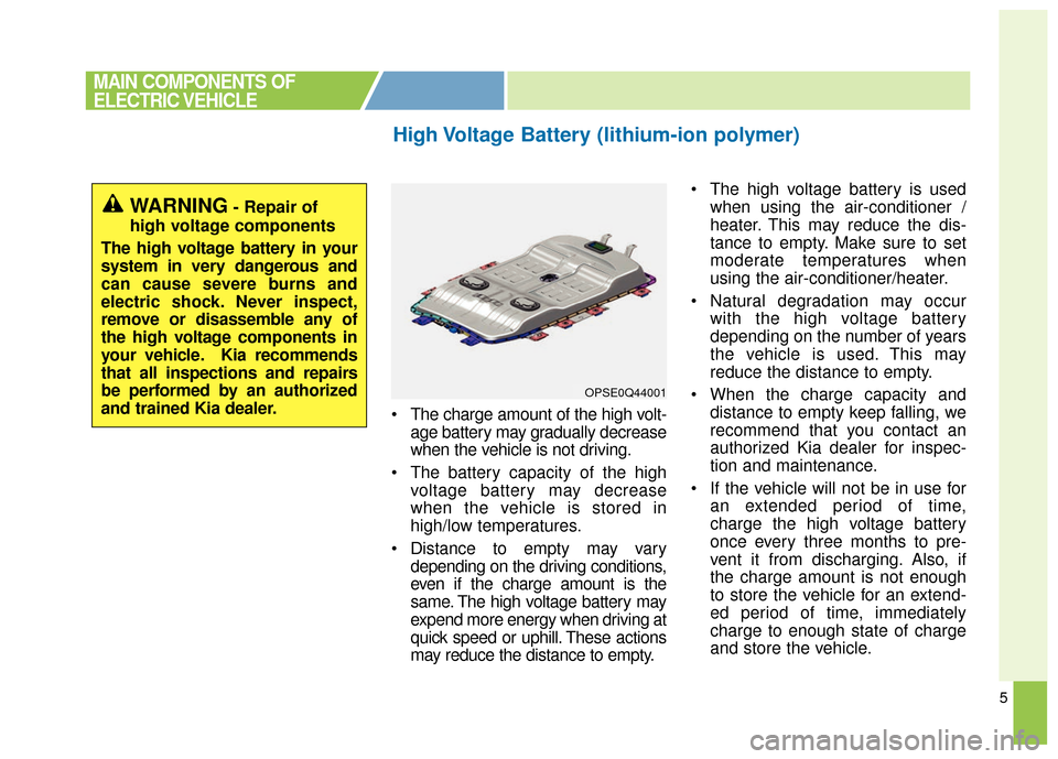
The charge amount of the high volt-age battery may gradually decrease
when the vehicle is not driving.
The battery capacity of the high voltage battery may decrease
when the vehicle is stored in
high/low temperatures.
Distance to empty may vary depending on the driving conditions,
even if the charge amount is the
same. The high voltage battery may
expend more energy when driving at
quick speed or uphill. These actions
may reduce the distance to empty. The high voltage battery is used
when using the air-conditioner /
heater. This may reduce the dis-
tance to empty. Make sure to set
moderate temperatures when
using the air-conditioner/heater.
Natural degradation may occur with the high voltage battery
depending on the number of years
the vehicle is used. This may
reduce the distance to empty.
When the charge capacity and distance to empty keep falling, we
recommend that you contact an
authorized Kia dealer for inspec-
tion and maintenance.
If the vehicle will not be in use for an extended period of time,
charge the high voltage battery
once every three months to pre-
vent it from discharging. Also, if
the charge amount is not enough
to store the vehicle for an extend-
ed period of time, immediately
charge to enough state of charge
and store the vehicle.
High Voltage Battery (lithium-ion polymer)
MAIN COMPONENTS OF
ELECTRIC VEHICLE
OPSE0Q44001
WARNING- Repair of
high voltage components
The high voltage battery in your
system in very dangerous and
can cause severe burns and
electric shock. Never inspect,
remove or disassemble any of
the high voltage components in
your vehicle. Kia recommends
that all inspections and repairs
be performed by an authorized
and trained Kia dealer.
Page 457 of 470
47
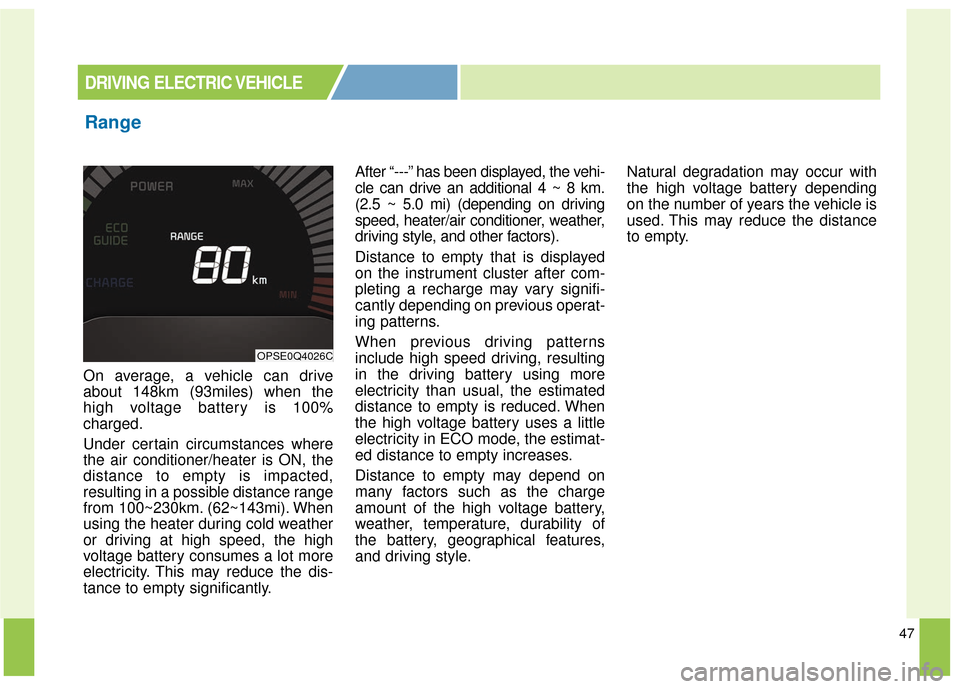
On average, a vehicle can drive
about 148km (93miles) when the
high voltage battery is 100%
charged.
Under certain circumstances where
the air conditioner/heater is ON, the
distance to empty is impacted,
resulting in a possible distance range
from 100~230km. (62~143mi). When
using the heater during cold weather
or driving at high speed, the high
voltage battery consumes a lot more
electricity. This may reduce the dis-
tance to empty significantly.After “---” has been displayed, the vehi-
cle can drive an additional 4 ~ 8 km.
(2.5 ~ 5.0 mi) (depending on driving
speed, heater/air conditioner, weather,
driving style, and other factors).
Distance to empty that is displayed
on the instrument cluster after com-
pleting a recharge may vary signifi-
cantly depending on previous operat-
ing patterns.
When previous driving patterns
include high speed driving, resulting
in the driving battery using more
electricity than usual, the estimated
distance to empty is reduced. When
the high voltage battery uses a little
electricity in ECO mode, the estimat-
ed distance to empty increases.
Distance to empty may depend on
many factors such as the charge
amount of the high voltage battery,
weather, temperature, durability of
the battery, geographical features,
and driving style.
Natural degradation may occur with
the high voltage battery depending
on the number of years the vehicle is
used. This may reduce the distance
to empty.
Range
DRIVING ELECTRIC VEHICLE
OPSE0Q4026C