2017 KIA Soul EV stop start
[x] Cancel search: stop startPage 299 of 470
63
What to do in an emergency
If the vehicle stalls at a cross-
road or crossing
If the vehicle stalls at a crossroad or
crossing, set the shift lever in the N
(Neutral) position and then push the
vehicle to a safe place.
If you have a flat tire while
driving
If a tire goes flat while you are driving:
1. Take your foot off the acceleratorpedal and let the vehicle slow
down while driving straight ahead.
Do not apply the brakes immedi-
ately or attempt to pull off the road
as this may cause a loss of control.
When the vehicle has slowed to
such a speed that it is safe to do
so, brake carefully and pull off the
road. Drive off the road as far as
possible and park on a firm level
ground. If you are on a divided
highway, do not park in the median
area between the two traffic lanes. 2. When the vehicle is stopped, turn
on your emergency hazard flash-
ers, set the parking brake and put
the transaxle in P.
3. Have all passengers get out of the vehicle. Be sure they all get out on
the side of the vehicle that is away
from traffic.
4. When changing a flat tire, follow the instruction provided later in
this section.
If the vehicle stalls while driv-
ing
1. Reduce your speed gradually,keeping a straight line. Move cau-
tiously off the road to a safe place.
2. Turn on your emergency flashers.
3. Try to start the vehicle again. If your vehicle will not start, contact
an authorized Kia dealer or seek
other qualified assistance.
IN CASE OF AN EMERGENCY WHILE DRIVING
Page 305 of 470
69
What to do in an emergency
TIRE PRESSURE MONITORING SYSTEM (TPMS)
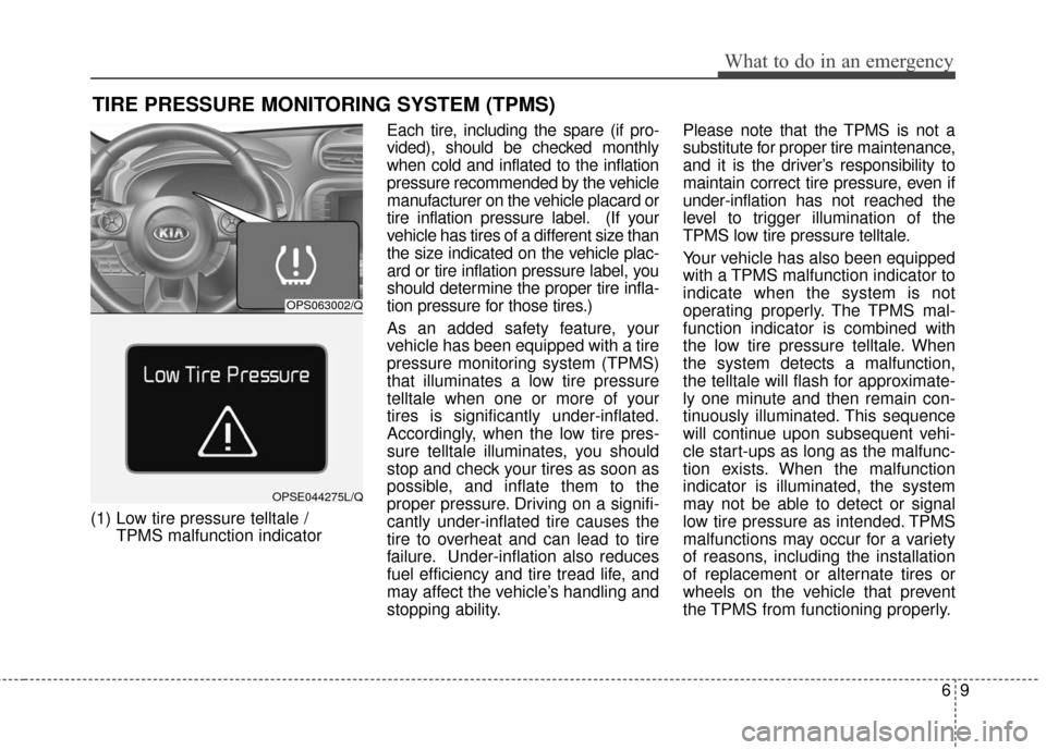
(1) Low tire pressure telltale / TPMS malfunction indicator Each tire, including the spare (if pro-
vided), should be checked monthly
when cold and inflated to the inflation
pressure recommended by the vehicle
manufacturer on the vehicle placard or
tire inflation pressure label. (If your
vehicle has tires of a different size than
the size indicated on the vehicle plac-
ard or tire inflation pressure label, you
should determine the proper tire infla-
tion pressure for those tires.)
As an added safety feature, your
vehicle has been equipped with a tire
pressure monitoring system (TPMS)
that illuminates a low tire pressure
telltale when one or more of your
tires is significantly under-inflated.
Accordingly, when the low tire pres-
sure telltale illuminates, you should
stop and check your tires as soon as
possible, and inflate them to the
proper pressure. Driving on a signifi-
cantly under-inflated tire causes the
tire to overheat and can lead to tire
failure. Under-inflation also reduces
fuel efficiency and tire tread life, and
may affect the vehicle’s handling and
stopping ability. Please note that the TPMS is not a
substitute for proper tire maintenance,
and it is the driver’s responsibility to
maintain correct tire pressure, even if
under-inflation has not reached the
level to trigger illumination of the
TPMS low tire pressure telltale.
Your vehicle has also been equipped
with a TPMS malfunction indicator to
indicate when the system is not
operating properly. The TPMS mal-
function indicator is combined with
the low tire pressure telltale. When
the system detects a malfunction,
the telltale will flash for approximate-
ly one minute and then remain con-
tinuously illuminated. This sequence
will continue upon subsequent vehi-
cle start-ups as long as the malfunc-
tion exists. When the malfunction
indicator is illuminated, the system
may not be able to detect or signal
low tire pressure as intended. TPMS
malfunctions may occur for a variety
of reasons, including the installation
of replacement or alternate tires or
wheels on the vehicle that prevent
the TPMS from functioning properly.
OPS063002/Q
OPSE044275L/Q
Page 306 of 470
What to do in an emergency
10
6
Always check the TPMS malfunction
telltale after replacing one or more
tires or wheels on your vehicle to
ensure that the replacement or alter-
nate tires and wheels allow the TPMS
to continue to function properly.
✽ ✽
NOTICE
If the TPMS, Low Tire Pressure
indicator do not illuminate for 3 sec-
onds when the ignition switch is
turned to the ON position or vehicle
is running, or if they remain illumi-
nated after coming on for approxi-
mately 3 seconds, take your vehicle
to your nearest authorized Kia deal-
er and have the system checked.
Low tire pressure
telltale
When the tire pressure monitoring
system warning indicators are illumi-
nated, one or more of your tires is
significantly under-inflated.
If the telltale illuminates, immediately
reduce your speed, avoid hard cor-
nering and anticipate increased stop-
ping distances. You should stop and
check your tires as soon as possible.
Inflate the tires to the proper pres-
sure as indicated on the vehicle’s
placard or tire inflation pressure label
located on the driver’s side center pil-
lar outer panel. If you cannot reach a
service station or if the tire cannot
hold the newly added air, replace the
low pressure tire with the spare tire. Then the Low Tire Pressure telltale
may flash for approximately one
minute and then remain continuously
illuminated after restarting and about
10 minutes of continuous driving at
speed above 25 km/h (15.5 mph)
before you have the low pressure tire
repaired and replaced on the vehicle.
In winter or cold weather, the low tire
pressure telltale may be illuminated if
the tire pressure was adjusted to the
recommended tire inflation pressure
in warm weather. It does not mean
your TPMS is malfunctioning because
the decreased temperature leads to a
proportional lowering of tire pressure.
When you drive your vehicle from a
warm area to a cold area or from a
cold area to a warm area, or the out-
side temperature is greatly higher or
lower, you should check the tire infla-
tion pressure and adjust the tires to
the recommended tire inflation pres-
sure.
Page 314 of 470

What to do in an emergency
18
6
8. With the vehicle start/stop button
position on or ignition switch posi-
tion on, switch on the compressor
and let it run for approximately
5~7 minutes to fill the sealant up
to proper pressure. (refer to the
Tire and Wheels, chapter 8). The
inflation pressure of the tire after
filling is unimportant and will be
checked/corrected later.
Be careful not to overinflate the
tire and stay away from the tire
when filling it. 9. Switch off the compressor.
10. Detach the hoses from the
sealant bottle connector and
from the tire valve.
Return the Tire Mobility Kit to its stor-
age location in the vehicle.Distributing the sealant
11. Immediately drive approximately 7~10km (4~6miles or, about
10min) to evenly distribute the
sealant in the tire.
Do not exceed a speed of 80 km/h
(50 mph). If possible, do not fall
below a speed of 20 km/h (12 mph).
While driving, if you experience any
unusual vibration, ride disturbance or
noise, reduce your speed and drive
with caution until you can safely pull
off of the side of the road.
Call for road side service or towing.
When you use the Tire Mobility Kit,
the tire pressure sensors and wheel
may be stained by sealant.
Therefore, remove the tire pressure
sensors and wheel stained by
sealant and we recommend that
inspect at an authorized Kia dealer.
WARNING - Carbon monoxide
Do not leave your vehicle run-
ning in a poorly ventilated area
for extended periods of time.
Carbon monoxide poisoning
and suffocation can occur.
WARNING- Tire pressure
Do not attempt to drive your
vehicle if the tire pressure is
below 200 kPa (29 psi).
This could result in an accident
due to sudden tire failure.
Page 373 of 470

Maintenance
54
7
Fuse Name Fuse rating Circuit Protected
MODULE 1 10A BCM IBAU 10A Integrated Brake Actuation Unit
MODULE 2 10A Tire Pressure Monitoring Module, Crash Pad Switch, Center Fascia Switch, Electronic Parking Brake
Module, Stop Lamp Switch, Rear Parking Assist Sensor RH/LH (IN/OUT), Front Parking Assit Sensor
LH/RH (OUT/IN)
MODULE 3 10A ATM Lever Indicator, Multipurpose Check Connector, PCB Block (IG3 #4 Relay) PDM 3 7.5A Smart Key Control Module
IOD 2 15A A/V & Navigation Head Unit
IOD 3 7.5A ICM Relay Box (Outside Mirror Folding Relay, Outside Mirror Unfolding Relay)
CLUSTER 10A Instrument Cluster IG1 15A EPCU
IOD 4 7.5A Instrument Cluster, Tire Pressure Monitoring Module, Data Link Connector, Multipurpose Check Connector,
A/C Control Module, BCM
FOG LAMP REAR 10A Rear Fog Lamp Control Block SUNROOF 2 20A SUNROOF_MOTOR (POWER)
SUNROOF 1 20A SUNROOF_MOTOR (POWER) MDPS 7.5A MDPS Unit
START 7.5A Transaxle Range Switch
IOD 1 7.5A Overhead Console Lamp, Vanity Lamp LH/RH, Room Lamp, Glove Box Lamp, Luggage Lamp
PDM 2 7.5A Smart Key Control Module
PDM 1 20A Smart Key Control Module
BRAKE SWITCH 10A Smart Key Control Module, Stop Lamp Switch
Page 375 of 470
Maintenance
56
7
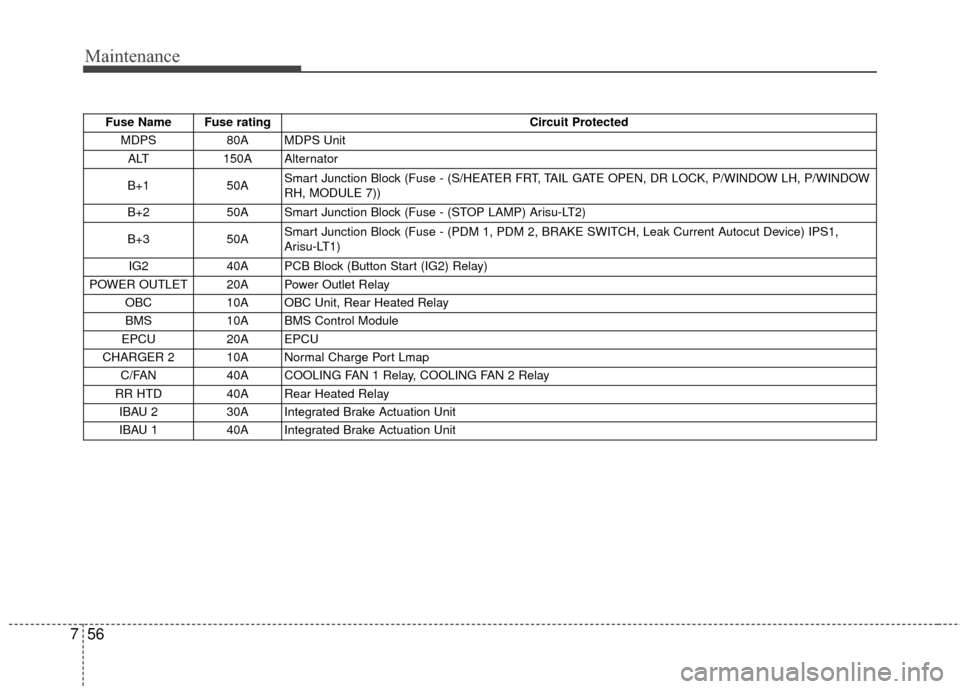
Fuse Name Fuse rating Circuit Protected
MDPS 80A MDPS Unit
ALT 150A Alternator
B+1 50A Smart Junction Block (Fuse - (S/HEATER FRT, TAIL GATE OPEN, DR LOCK, P/WINDOW LH, P/WINDOW
RH, MODULE 7))
B+2 50A Smart Junction Block (Fuse - (STOP LAMP) Arisu-LT2)
B+3 50A Smart Junction Block (Fuse - (PDM 1, PDM 2, BRAKE SWITCH, Leak Current Autocut Device) IPS1,
Arisu-LT1)
IG2 40A PCB Block (Button Start (IG2) Relay)
POWER OUTLET 20A Power Outlet Relay OBC 10A OBC Unit, Rear Heated Relay
BMS 10A BMS Control Module
EPCU 20A EPCU
CHARGER 2 10A Normal Charge Port Lmap C/FAN 40A COOLING FAN 1 Relay, COOLING FAN 2 Relay
RR HTD 40A Rear Heated Relay IBAU 2 30A Integrated Brake Actuation Unit
IBAU 1 40A Integrated Brake Actuation Unit
Page 411 of 470
Electric Vehicle Guide
❈This is an electric vehicle guide to assist drivers with
understanding their vehicle.
Refer to the following content for electric vehicle details
and precautions
Review of Electric Vehicle ........................................................2
Main Components of Electric Vehicle.......................................4
High voltage battery .................................................................5
EV Mode ........................................................................\
..........7
■ Available Range .................................................................7■ Near by stations .................................................................8■ Energy Information. ............................................................8■ ECO Driving .......................................................................9\
■ Setting Charging Times .....................................................9■ Setting Climate Times ......................................................11■ EV Setting ........................................................................\
11
Charge Types for Electric Vehicle...........................................13
Charge Indicator Lamp for Electric Vehicle ............................15
Reserved Charging ................................................................16
Reserved Climate Control. .....................................................18
Precautions for Charging Electric Vehicle ..............................19
Charging Electric Vehicle (Normal Charge) ...........................22
■ How to Connect Normal Charger .....................................22■ Unlock Charging Door in Emergency ...............................25■ Emergency Release of the Charging connector
lock system .......................................................................2\
6
■ Checking Charging Status................................................26■ How to Disconnect Normal Charger ................................27
Charging Electric Vehicle (Quick Charge) ..............................28
■ How to Connect Quick Charger .......................................28■ Unlock Charging Door in Emergency ...............................31■ Checking Charging Status................................................31■ How to Disconnect Quick Charger ...................................32
Charging Electric Vehicle (Trickle Charge) .............................34
■ How to Connect Portable Charging Cable .......................34■ Unlock Charging Door in Emergency ...............................38■ Emergency Release of the Charging connector
lock system .......................................................................3\
9
■ Checking Charging Status................................................39■ Charging Status Indicator Lamp for Portable Charging
Cable ........................................................................\
........40
■ How to Disconnect Portable Charging Cable ..................41■ Precautions for Portable Charging Cable .........................43
Driving Electric Vehicle ...........................................................44
■ How to Start the Vehicle ...................................................44■ How to Stop the Vehicle ...................................................45■ Pedestrian Warning System .............................................46■ Active ECO system ..........................................................46■ Range ........................................................................\
.......47■ Tips for Improving Distance to Empty ..............................48■ Motor Operation Gauge....................................................48■ State of charge (SOC) gauge for high voltage battery.....49■ Warning Message on LCD Display (related to charge)....50■ Warning Lamp and Indicator Lamp
(related to electric vehicle) ...............................................53
Safety Precautions for Electric Vehicle...................................56
■ Service Plug .....................................................................59
Environmental Friendliness Mark ...........................................59
Page 434 of 470
24
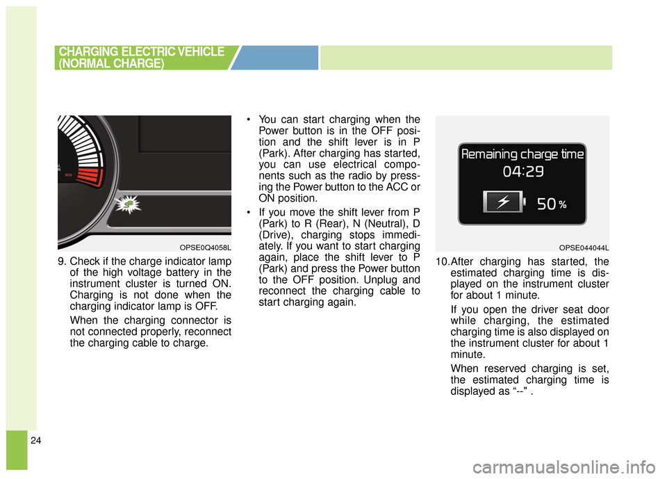
9. Check if the charge indicator lampof the high voltage battery in the
instrument cluster is turned ON.
Charging is not done when the
charging indicator lamp is OFF.
When the charging connector is
not connected properly, reconnect
the charging cable to charge. You can start charging when the
Power button is in the OFF posi-
tion and the shift lever is in P
(Park). After charging has started,
you can use electrical compo-
nents such as the radio by press-
ing the Power button to the ACC or
ON position.
If you move the shift lever from P (Park) to R (Rear), N (Neutral), D
(Drive), charging stops immedi-
ately. If you want to start charging
again, place the shift lever to P
(Park) and press the Power button
to the OFF position. Unplug and
reconnect the charging cable to
start charging again. 10.After charging has started, the
estimated charging time is dis-
played on the instrument cluster
for about 1 minute.
If you open the driver seat door
while charging, the estimated
charging time is also displayed on
the instrument cluster for about 1
minute.
When reserved charging is set,
the estimated charging time is
displayed as “--" .
OPSE0Q4058LOPSE044044L
CHARGING ELECTRIC VEHICLE
(NORMAL CHARGE)