Page 386 of 488

Maintenance
8
7
NORMAL MAINTENANCE SCHEDULE
The following maintenance services must be performed to ensure good emission control and performance. Keep receipts for all
vehicle emission services to protect your warranty. Where both mileage and time are shown, the frequency of service is deter-
mined by whichever occurs first. * 1
: Adjust alternator, water pump and air conditioner (if equipped)
drive belt. Inspect and if necessary repair or replace.
If drive belt noise occurred, readjust drive belt tension before
replace.
* 2
: Check the engine oil level and leak every 500 km (350
miles) or before starting a long trip.
* 3
: For your convenience, it can be replaced prior to it's interval
when you do maintenance of other items.
* 4
: Inspect for excessive valve noise and/or engine vibration
and adjust if necessary. We recommend that the system be
serviced by an authorized Kia dealer.
* 5
: The fuel filter is considered to be maintenance free but peri-
odic inspection is recommended for this maintenance
schedule depends on fuel quality. If there are some impor-
tant matters like fuel flow restriction, surging, loss of power,
hard starting problem etc, replace the fuel filter immediate-
ly regardless of maintenance schedule and we recommend
that you consult an authorized Kia dealer for details. *
6
: When adding coolant, use only deionized water or soft
water for your vehicle and never mix hard water in the
coolant filled at the factory. An improper coolant mixture can
result in serious malfunction or engine damage.
* 7
: Kia recommends that you use good quality gasolines meet
Europe Fuel standards (EN228) or equivalents.
For customers who do not use good quality gasolines
including fuel additives regularly, and have problems start-
ing or the engine does not run smoothly, one bottle of addi-
tives added to the fuel tank at every 15,000km(For Europe)/ 10,000km(Except Europe) is recommended.
Additves are available from your authorized Kia dealer
along with information on how to use them. Do not mix other
additves.
Page 443 of 488

765
Maintenance
SymbolFuse ratingProtected Component
MULTI FUSE80AEPS Control Module
125AAlternator, PCB Fuse & Relay Box
FUSE
50AI/P Junction Box (Power Connector Fuse : F1 10A / F2 20A,
Fuse : F24 10A / F25 10A / F26 10A / F27 15A, Tail Lamp Relay)
40AProjection Type : E/R Sub Fuse Box (Fuse : F1 10A / F2 20A / F4 15A / F5 10A / F7 10A )
50AI/P Junction Box (Fuse : F8 20A / F9 25A / F10 15A / F16 15A / F17 25A / F18 15A / F19 10A
/ F35 10A, Power Window Relay)
40AE/R Junction Box (Fuse : F11 15A), Ignition Switch, PDM Relay Box (ESCL Relay)
40AABS Control Relay, ESC Control Relay
30AABS Control Relay, ESC Control Relay
40ARear Defogger Relay
40APCB Fuse & Relay Box (Start Relay), Ignition Switch, PDM Relay Box (ESCL Relay)
30APCB Fuse & Relay Box (Engine Control Relay, Fuse : F23 10A)
40APCB Fuse & Relay Box (Blower Relay)
40APCB Fuse & Relay Box (Cooling Fan Relay)
FUSE
(General head light type)10AInstrument Cluster, Head Lamp RH, PCB Fuse & Relay Box (Head Lamp (HI) Relay)
2FUEL PUMP
(FFV)
VACCUM PUMP (EU K3 AT)
15APCB Fuse & Relay Box (Fuel Pump #2 Relay)
Engine compartment main fuse panel
Page 444 of 488

Maintenance
66
7
SymbolFuse ratingProtected Component
FUSE
(General head light type)
1FUEL
PUMP15APCB Fuse & Relay Box (Fuel Pump #1 Relay)
20APCB Fuse & Relay Box (Head Lamp (HI) Relay)
20APCB Fuse & Relay Box (Head Lamp (LO) Relay)
10APCB Fuse & Relay Box (Horn Relay, Burglar Alarm Horn Relay)
10APCB Fuse & Relay Box (A/C Relay)
10APCM (B3LA)
10ATCM (F3LA/F4LA/F3LA), PCM (B3LA)
10ATransaxle Range Switch, TCM/PCM, ESC Control Module, Rear Bumper Lamp,
Instrument Cluster, BCM, Back-Up Lamp LH/RH, Back-Up Lamp Switch
10AECM/PCM, Front Wiper Motor, Multifunction Switch
20AIgnition coil, condensor
15ATCM/PCM, Injector #1/#2/#3, Injector #4 (G4LA), Jumper Wire 1, Crash Pad Switch (B4LA),
Fuel Pump #2 Relay (B3LA)
10AHead Lamp LH
10A
G3LA/G4LA/F3LA : TCM/ECM, Camshaft Position Sensor #1/#2, Oxygen Sensor (UP)/(DOWN),
Canister Purge Solenoid Valve, Oil Control Valve #1/#2, PCB Fuse & Relay Box (A/C Relay,
Cooling Fan Relay, Start Relay), B3LA : PCM, Camshaft Position Sensor #1/#2,
PCB Fuse & Relay Box (A/C Relay, Cooling Fan Relay), Oxygen Sensor (UP)/(DOWN),
Canister Purge Solenoid Valve, Oil Control Valve #1/#2, Variable Intake Solenoid Valve
10AHead Lamp RH
Page 445 of 488

767
Maintenance
SymbolFuse ratingProtected Component
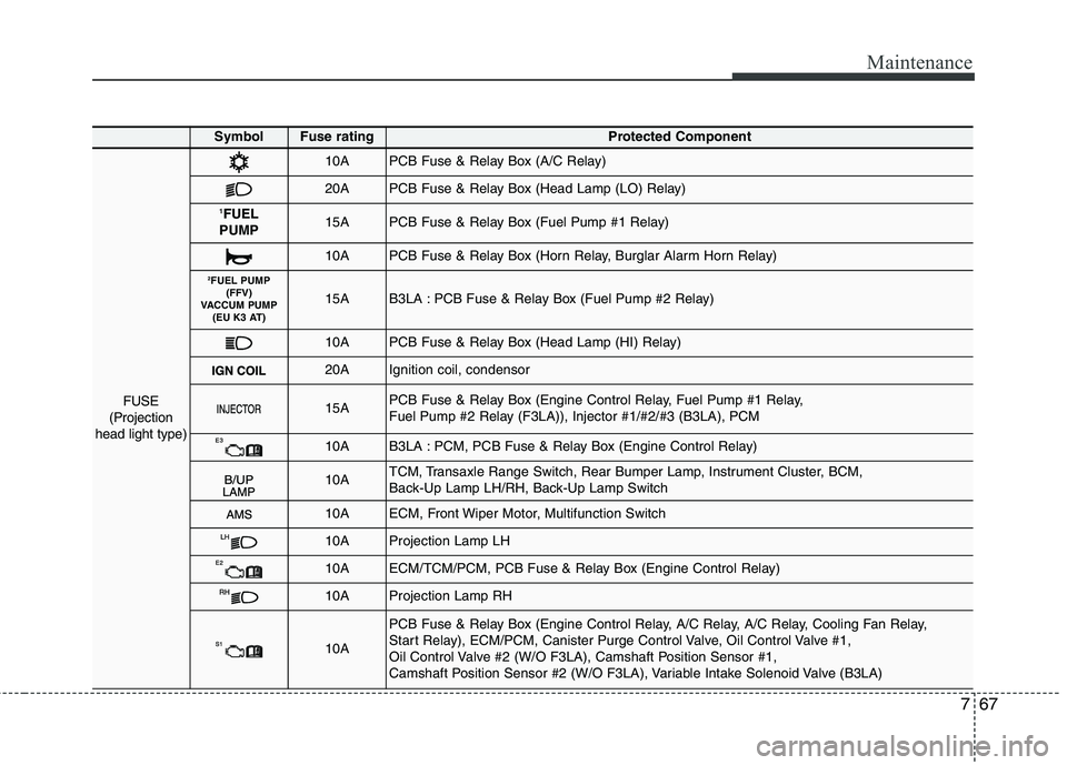
FUSE
(Projection
head light type)
10APCB Fuse & Relay Box (A/C Relay)
20APCB Fuse & Relay Box (Head Lamp (LO) Relay)
1 FUEL
PUMP15APCB Fuse & Relay Box (Fuel Pump #1 Relay)
10APCB Fuse & Relay Box (Horn Relay, Burglar Alarm Horn Relay)
2 FUEL PUMP
(FFV)
VACCUM PUMP (EU K3 AT)
15AB3LA : PCB Fuse & Relay Box (Fuel Pump #2 Relay)
10APCB Fuse & Relay Box (Head Lamp (HI) Relay)
20AIgnition coil, condensor
15APCB Fuse & Relay Box (Engine Control Relay, Fuel Pump #1 Relay,
Fuel Pump #2 Relay (F3LA)), Injector #1/#2/#3 (B3LA), PCM
10AB3LA : PCM, PCB Fuse & Relay Box (Engine Control Relay)
10ATCM, Transaxle Range Switch, Rear Bumper Lamp, Instrument Cluster, BCM,
Back-Up Lamp LH/RH, Back-Up Lamp Switch
10AECM, Front Wiper Motor, Multifunction Switch
10AProjection Lamp LH
10AECM/TCM/PCM, PCB Fuse & Relay Box (Engine Control Relay)
10AProjection Lamp RH
10A
PCB Fuse & Relay Box (Engine Control Relay, A/C Relay, A/C Relay, Cooling Fan Relay,
Start Relay), ECM/PCM, Canister Purge Control Valve, Oil Control Valve #1,
Oil Control Valve #2 (W/O F3LA), Camshaft Position Sensor #1,
Camshaft Position Sensor #2 (W/O F3LA), Variable Intake Solenoid Valve (B3LA)