2017 KIA FORTE KOUP instrument cluster
[x] Cancel search: instrument clusterPage 385 of 595
Driving your vehicle
42 5
The VSM does not operate when:
• Driving on bank roads such as gra-
dient or incline
• Driving rearward
• ESC OFF indicator light ( )
remains on the instrument
cluster
• EPS indicator light remains on the
instrument clusterVSM operation off
If you press the ESC OFF button to
turn off the ESC, the VSM will also
cancel and the ESC OFF indicator
light ( ) illuminates.
To turn on the VSM, press the button
again. The ESC OFF indicator light
goes out.
Malfunction indicator
The VSM can be deactivated even if
you don’t cancel the VSM operation
by pressing the ESC OFF button. It
indicates that a malfunction has
been detected somewhere in the
Electric Power Steering system or
VSM system. If the ESC indicator
light ( ) or EPS warning light
remains on, take your vehicle to an
authorized Kia dealer and have the
system checked.
• The VSM is designed to function
above approximately 15 km/h (9
mph) on curves.• The VSM is designed to function
above approximately 30 km/h (18
mph) when a vehicle is braking on
a split-mu road. The split-mu road
is made of surfaces which have dif-
ferent friction forces.
• The Vehicle Stability Management
system is not a substitute for safe
driving practices but a supplemen-
tary function only. It is the respon-
sibility of the driver to always check
the speed and the distance to the
vehicle ahead. Always hold the
steering wheel firmly while driving.
• Your vehicle is designed to activate
according to the driver’s intention,
even with installed VSM. Always
follow all the normal precautions
for driving at safe speeds for the
conditions – including driving in
inclement weather and on a slip-
pery road.
Page 389 of 595
Driving your vehicle
46 5
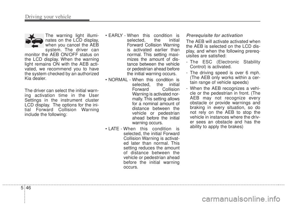
The warning light illumi-
nates on the LCD display,
when you cancel the AEB
system. The driver can
monitor the AEB ON/OFF status on
the LCD display. When the warning
light remains ON with the AEB acti-
vated, we recommend you to have
the system checked by an authorized
Kia dealer.
The driver can select the initial warn-
ing activation time in the User
Settings in the instrument cluster
LCD display. The options for the ini-
tial Forward Collision Warning
include the following:• EARLY - When this condition is
selected, the initial
Forward Collision Warning
is activated earlier than
normal. This setting maxi-
mizes the amount of dis-
tance between the vehicle
or pedestrian ahead before
the initial warning occurs.
• NORMAL - When this condition is
selected, the initial
Forward Collision
Warning is activated nor-
mally. This setting allows
for a nominal amount of
distance between the
vehicle or pedestrian
ahead before the initial
warning occurs.
• LATE - When this condition is
selected, the initial Forward
Collision Warning is activat-
ed later than normal. This
setting reduces the amount
of distance between the
vehicle or pedestrian ahead
before the initial warning
occurs.Prerequisite for activation
The AEB will activate activated when
the AEB is selected on the LCD dis-
play, and when the following prereq-
uisites are satisfied:
- The ESC (Electronic Stability
Control) is activated.
- The driving speed is over 6 mph.
(The AEB only works within a cer-
tain range of vehicle speeds)
- When the AEB recognizes a vehi-
cle or the pedestrian in front. (The
AEB may not recognize every
obstacle or provide warnings and
braking in every situation, so do
not rely on the AEB to stop the
vehicle in instances where the driv-
er sees an obstacle and has the
ability to apply the brakes)
Page 400 of 595
557
Driving your vehicle
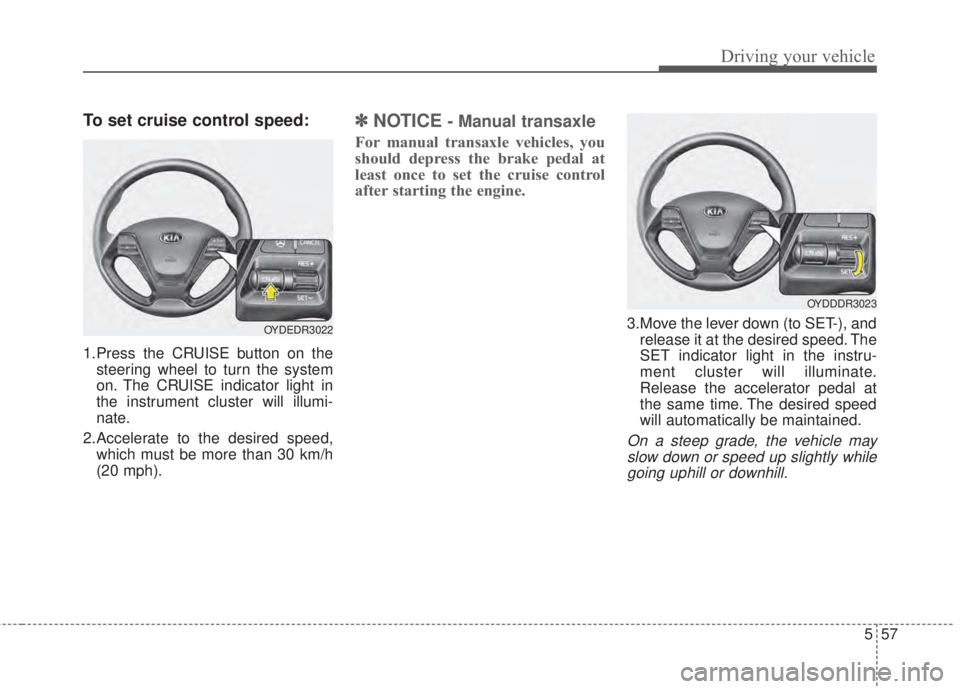
To set cruise control speed:
1.Press the CRUISE button on the
steering wheel to turn the system
on. The CRUISE indicator light in
the instrument cluster will illumi-
nate.
2.Accelerate to the desired speed,
which must be more than 30 km/h
(20 mph).
✽NOTICE- Manual transaxle
For manual transaxle vehicles, you
should depress the brake pedal at
least once to set the cruise control
after starting the engine.
3.Move the lever down (to SET-), and
release it at the desired speed. The
SET indicator light in the instru-
ment cluster will illuminate.
Release the accelerator pedal at
the same time. The desired speed
will automatically be maintained.
On a steep grade, the vehicle may
slow down or speed up slightly while
going uphill or downhill.
OYDEDR3022
OYDDDR3023
Page 403 of 595
Driving your vehicle
60 5
✽NOTICE
Always check the road conditions
when you move the lever up (to
RES+) to resume the speed.
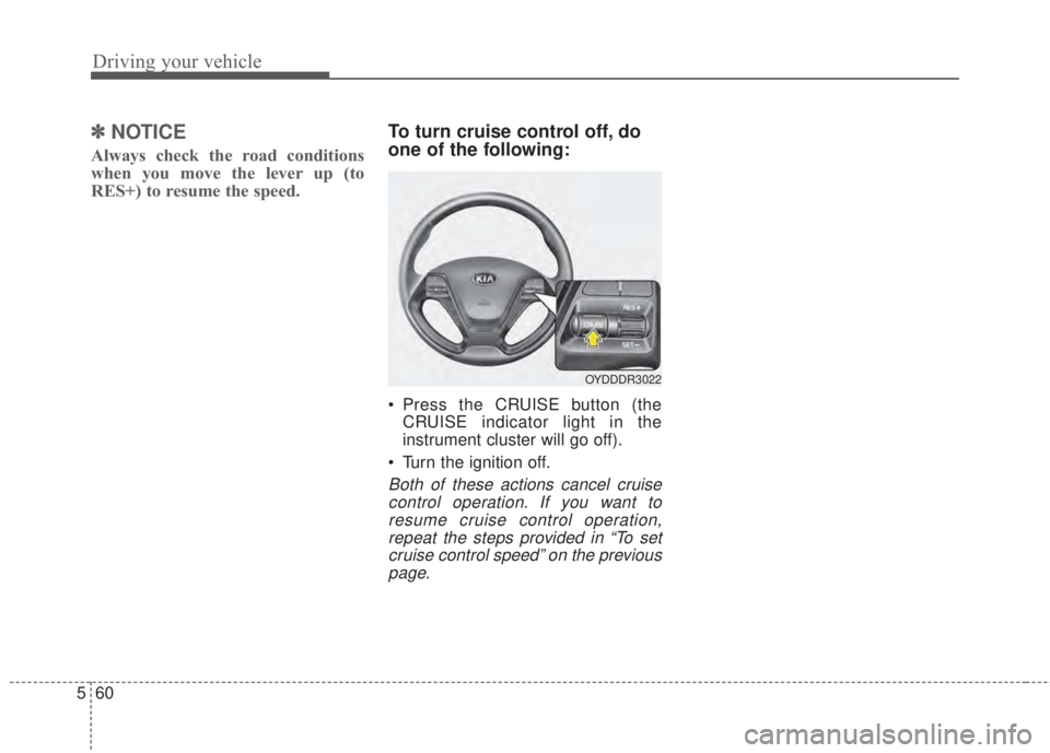
To turn cruise control off, do
one of the following:
• Press the CRUISE button (the
CRUISE indicator light in the
instrument cluster will go off).
• Turn the ignition off.
Both of these actions cancel cruise
control operation. If you want to
resume cruise control operation,
repeat the steps provided in “To set
cruise control speed” on the previous
page.
OYDDDR3022
Page 419 of 595
Driving your vehicle
76 5
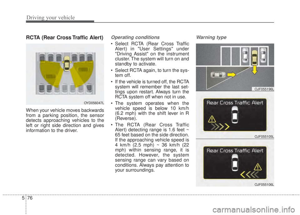
RCTA (Rear Cross Traffic Alert)
When your vehicle moves backwards
from a parking position, the sensor
detects approaching vehicles to the
left or right side direction and gives
information to the driver.
Operating conditions
• Select RCTA (Rear Cross Traffic
Alert) in "User Settings" under
"Driving Assist" on the instrument
cluster. The system will turn on and
standby to activate.
• Select RCTA again, to turn the sys-
tem off.
• If the vehicle is turned off, the RCTA
system will remember the last set-
tings upon restart. Always turn the
RCTA system off when not in use.
• The system operates when the
vehicle speed is below 10 km/h
(6.2 mph) with the shift lever in R
(Reverse).
• The RCTA (Rear Cross Traffic
Alert) detecting range is 1.6 feet ~
65 feet based on the side direction.
If the approaching vehicle speed is
4 km/h (2.5 mph) ~ 36 km/h (22
mph) within sensing range, it is
detected. However, the system
sensing range can vary based on
conditions. Always pay attention to
your surroundings.
Warning type
OYD056047L
OJF055105L
OJF055196L
OJF055106L
Page 539 of 595

777
Maintenance
Instrument panel fuse panel
Fuse Name Fuse rating Circuit Protected
P/SEAT DRV 30A Driver IMS Module, Driver Seat Manual Switch
SPARE 4 25A -
P/WDW RH 25A Smart Junction Block (Power Window RH Relay), Passenger Safety Power Window Module
TRUNK 10A Smart Junction Box (Trunk Relay)
P/WDW LH 25A Smart Junction Block (Power Window LH Relay), Driver Safety Power Window Module
DR LOCK 20A Smart Junction Block (Door Lock Relay, Door Unlock Relay), ICM Relay Box (Two Turn Unlock Relay)
SPARE 3 20A -
POWER OUTLET 1 20A Cigarette Lighter & Power Outlet (Cigarette Lighter)
S/HEATER RR 20A Rear Seat Warmer LH/RH
MODULE 8 10A BCM, Smart Key Control Module
SPARE 2 7.5A -
MODULE 9 15A Driver/Passenger Smart Key Outside Handle, Driver/Passenger Power Outside Handle
MODULE 1 10ASmart Key Control Module, BCM, Digital Clock, Audio, A/V & Navigation Head Unit, Power Outside
Mirror Switch
A/CON 7.5A A/C Control Module, Cluster Ionizer, E/R Junction Block (Blower Relay, GSL PTC Heater Relay)
MODULE 5 7.5ADriver/Passenger Seat Warmer Module, Driver Passenger Air Ventilation Seat Control Module, Rear
Seat Warmer LH/RH, Sunroof
HTD MIRR 10A ECM/PCM, A/C Control Module, Driver/Passenger Power Outside Mirror
INTERIOR LAMP 7.5ATrunk Room Lamp, Glove Box Lamp, Vanity Lamp LH/RH, Room Lamp, Overhead Console Lamp,
Ignition Key ILL. & Door Warning Switch, Luggage Lamp
MODULE 6 7.5A Key Solenoid
PDM 2 7.5A [With Smart Key] Smart Key Control Module [W/O Smart Key] Immobilizer Module
SUNROOF 20ASunroof
Page 540 of 595

Maintenance
78 7
Fuse Name Fuse rating Circuit Protected
MODULE 2 10A Electro Chromic Mirror, Multipurpose Check Connector, A/C Control Module, Driver CCS Switch,
Driver/Passenger Air Ventilation Seat Control Module, Driver/Passenger Seat Warmer Module, Driver
IMS Module, A/V & Navigation Head Unit, ATM Lever Indicator, Rear Seat Warmer LH/RH, Rear Power
Window Switch LH/RH, Rear Seat Warmer LH/RH, Audio, Dynamic Bending Light Module, Console
Switch LH/RH
HTD STRG 15A Steering Wheel Heater
IG 1 20A W/O Smart Key : E/R Junction Block (Fuse - TCU1, ECU 3, ABS 3)
WIPER FRT 25A Wiper Motor, E/R Junction Block (Wiper Relay), Multifunction Switch (Wiper)
MULTIMEDIA 2 7.5A -
MEMORY 7.5ADriver IMS Module, BCM, Tire Pressure Monitoring Module, Auto Light & Photo Sensor, Instrument
Cluster, Data Link Connector, Digital Clock, A/C Control Module, Electro Chromic Mirror,
MODULE 7 10A ICM Relay Box (Turn Signal Lamp Sound Relay, Folding Relay, Unfolding Relay)
PDM 3 7.5A [With Smart Key] Smart Key Control Module [W/O Smart Key] Immobilizer Module
MDPS 7.5A MDPS Unit
MODULE 3 7.5A Instrument Cluster
START 7.5A[With Burglar Alarm & W/O Smart Key & W/O IMMO.] ICM Relay Box (Burglar Alarm Relay)
[W/O Burglar Alarm or With Smart Key or With IMMO.] Transaxle Range Switch, Ignition Lock Switch
MULTIMEDIA 1 15A Audio, A/V & Navigation Head Unit
BRAKE SWITCH 10A Stop Lamp Switch, Smart Key Control Module
PDM 1 20A Smart Key Control Module
POWER OUTLET FRT 20A Cigarette Lighter & Power Outlet (Power Outlet)
A/BAG IND 7.5A Instrument Cluster (Air Bag IND.)
MODULE 4 10ACrash Pad Switch, Tire Pressure Monitoring Module, Stop Lamp Switch, Digital Clock, BCM, Blind Spot
Detection Radar LH/RH, MDPS Unit, AEB Module,
Sport Mode Switch, AEB Radar
A/BAG 15A SRS Control Module, Weight Classification Module
Page 591 of 595

I5
Index
Jack and tools . . . . . . . . . . . . . . . . . . . . . . . . . . . . . . 6-13
Jack label . . . . . . . . . . . . . . . . . . . . . . . . . . . . . . . . . 6-21
Removing and storing the spare tire . . . . . . . . . . . . 6-14
If you have a flat tire (with Tire Mobility Kit). . . . . . . . 6-7
Checking the tire inflation pressure . . . . . . . . . . . . . 6-11
Components of the Tire Mobility Kit . . . . . . . . . . . . 6-9
Distributing the sealant . . . . . . . . . . . . . . . . . . . . . . 6-11
Introduction . . . . . . . . . . . . . . . . . . . . . . . . . . . . . . . . 6-7
Notes on the safe use of the Tire Mobility Kit . . . . . 6-8
Technical Data . . . . . . . . . . . . . . . . . . . . . . . . . . . . . 6-12
Using the Tire Mobility Kit . . . . . . . . . . . . . . . . . . . 6-10
In case of an emergency while driving . . . . . . . . . . . . . . 6-3
If engine stalls while driving . . . . . . . . . . . . . . . . . . . 6-3
If the engine stalls at a crossroad or crossing . . . . . . 6-3
If you have a flat tire while driving . . . . . . . . . . . . . . 6-3
Instrument cluster . . . . . . . . . . . . . . . . . . . . . . . . . . . . . 4-58
Gauges . . . . . . . . . . . . . . . . . . . . . . . . . . . . . . . . . . . 4-60
Instrument cluster control . . . . . . . . . . . . . . . . . . . . 4-59
LCD window control . . . . . . . . . . . . . . . . . . . . . . . . 4-59
Transaxle shift indicator . . . . . . . . . . . . . . . . . . . . . . 4-62
Instrument panel overview . . . . . . . . . . . . . . . . . . . . . . . 2-5
Interior features. . . . . . . . . . . . . . . . . . . . . . . . . . . . . . 4-141
Ashtray . . . . . . . . . . . . . . . . . . . . . . . . . . . . . . . . . . 4-141
Cigarette lighter . . . . . . . . . . . . . . . . . . . . . . . . . . . 4-141
Climate control seat . . . . . . . . . . . . . . . . . . . . . . . . 4-145
Coat hook . . . . . . . . . . . . . . . . . . . . . . . . . . . . . . . . 4-148
Covering shelf (5 Door) . . . . . . . . . . . . . . . . . . . . . 4-150Cup holder . . . . . . . . . . . . . . . . . . . . . . . . . . . . . . . 4-142
Floor mat anchor(s) . . . . . . . . . . . . . . . . . . . . . . . . 4-148
LCD monitor (Clock) . . . . . . . . . . . . . . . . . . . . . . . 4-147
Luggage net (Holder) . . . . . . . . . . . . . . . . . . . . . . . 4-149
Navigation system . . . . . . . . . . . . . . . . . . . . . . . . . 4-151
Power outlet . . . . . . . . . . . . . . . . . . . . . . . . . . . . . . 4-146
Seat warmer . . . . . . . . . . . . . . . . . . . . . . . . . . . . . . 4-143
Sliding armrest . . . . . . . . . . . . . . . . . . . . . . . . . . . . 4-142
Sunvisor . . . . . . . . . . . . . . . . . . . . . . . . . . . . . . . . . 4-143
Interior light . . . . . . . . . . . . . . . . . . . . . . . . . . . . . . . . 4-108
Automatic turn off function . . . . . . . . . . . . . . . . . . 4-108
Glove box lamp . . . . . . . . . . . . . . . . . . . . . . . . . . . 4-111
Luggage room lamp . . . . . . . . . . . . . . . . . . . . . . . . 4-110
Map lamp . . . . . . . . . . . . . . . . . . . . . . . . . . . . . . . . 4-108
Room lamp . . . . . . . . . . . . . . . . . . . . . . . . . . . . . . . 4-109
Vanity mirror lamp . . . . . . . . . . . . . . . . . . . . . . . . . 4-111
Interior overview. . . . . . . . . . . . . . . . . . . . . . . . . . . . . . . 2-4
Key positions . . . . . . . . . . . . . . . . . . . . . . . . . . . . . . . . . 5-6
Ignition switch position . . . . . . . . . . . . . . . . . . . . . . . 5-6
Illuminated ignition switch . . . . . . . . . . . . . . . . . . . . 5-6
Keys . . . . . . . . . . . . . . . . . . . . . . . . . . . . . . . . . . . . . . . . 4-4
Key operations . . . . . . . . . . . . . . . . . . . . . . . . . . . . . . 4-4
Record your key number . . . . . . . . . . . . . . . . . . . . . . 4-4
K