Page 3 of 615

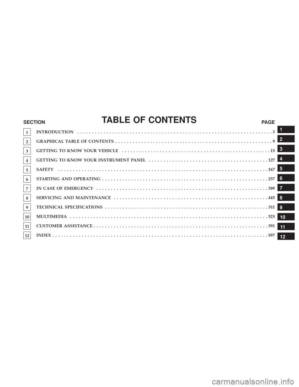
TABLE OF CONTENTSSECTIONPAGE
1INTRODUCTION
...................................................................3
2GRAPHICAL TABLE OF CONTENTS
......................................................9
3GETTING TO KNOW YOUR VEHICLE
...................................................15
4GETTING TO KNOW YOUR INSTRUMENT PANEL
.........................................127
5SAFETY
........................................................................\
167
6STARTINGANDOPERATING.........................................................257
7INCASEOFEMERGENCY ...........................................................389
8SERVICING AND MAINTENANCE
.....................................................445
9TECHNICAL SPECIFICATIONS
........................................................511
10MULTIMEDIA ....................................................................525
11CUSTOMER ASSISTANCE
............................................................591
12INDEX........................................................................\
..597
1
2
3
4
5
6
7
8
9
10 11
12
Page 423 of 615
9. Install the wheel bolts with the threaded end of thewheel bolt toward the wheel. Lightly tighten the wheel
bolts.
WARNING!
To avoid the risk of forcing the vehicle off the jack, do
not tighten the wheel nuts fully until the vehicle has
been lowered. Failure to follow this warning may
result in serious injury.
10. Lower the vehicle to the ground by turning the jack handle counterclockwise.
11. Finish tightening the wheel bolts. Push down on the wrench while at the end of the handle for increased
leverage. Tighten the wheel bolts in a star pattern until
each wheel bolt has been tightened twice. Refer to
“Torque Specifications” in “Technical Specifications”
for the proper lug bolt torque. If in doubt about the
correct tightness, have them checked with a torque
wrench by your authorized dealer or at a service
station. 12. Securely stow the jack, tools, chocks and flat tire.
Assembled Jack
7
IN CASE OF EMERGENCY 421
Page 424 of 615

WARNING!
A loose tire or jack thrown forward in a collision or
hard stop could endanger the occupants of the vehicle.
Always stow the jack parts and the spare tire in the
places provided. Have the deflated (flat) tire repaired
or replaced immediately.
Road Tire Installation
1. Mount the road tire on the axle.
2. Install the remaining wheel bolts with the threaded endof the wheel bolt toward the wheel. Lightly tighten the
wheel bolts.
WARNING!
To avoid the risk of forcing the vehicle off the jack, do
not tighten the wheel nuts fully until the vehicle has
been lowered. Failure to follow this warning may
result in serious injury.
3. Lower the vehicle to the ground by turning the jack handle counterclockwise.
4. Finish tightening the wheel bolts. Push down on the wrench while at the end of the handle for increased
leverage. Tighten the wheel bolts in a star pattern until
each wheel bolt has been tightened twice. Refer to
“Torque Specifications” in “Technical Specifications” for
the proper lug bolt torque. If in doubt about the correct
tightness, have them checked with a torque wrench by
your authorized dealer or service station.
Stowed Tire, Jack And Chock
422 IN CASE OF EMERGENCY
Page 481 of 615

WARNING!
•Use only manufacturer’s recommended brake fluid.
Refer to “Fluids And Lubricants” in “Technical
Specifications” for further information. Using the
wrong type of brake fluid can severely damage your
brake system and/or impair its performance. The
proper type of brake fluid for your vehicle is also
identified on the original factory installed hydraulic
master cylinder reservoir.
• To avoid contamination from foreign matter or mois-
ture, use only new brake fluid or fluid that has been
in a tightly closed container. Keep the master cylin-
der reservoir cap secured at all times. Brake fluid in
a open container absorbs moisture from the air
resulting in a lower boiling point. This may cause it
to boil unexpectedly during hard or prolonged brak-
ing, resulting in sudden brake failure. This could
result in a collision.
• Overfilling the brake fluid reservoir can result in
spilling brake fluid on hot engine parts, causing the
brake fluid to catch fire. Brake fluid can also damage
painted and vinyl surfaces, care should be taken to
avoid its contact with these surfaces.
(Continued)
WARNING! (Continued)
•Do not allow petroleum based fluid to contaminate
the brake fluid. Brake seal components could be
damaged, causing partial or complete brake failure.
This could result in a collision.
Automatic Transmission
Selection Of Lubricant
It is important to use the proper transmission fluid to
ensure optimum transmission performance and life. Use
only the manufacturer’s specified transmission fluid. Refer
to “Fluids And Lubricants” in “Technical Specifications”
for fluid specifications. It is important to maintain the
transmission fluid at the correct level using the recom-
mended fluid.
NOTE: No chemical flushes should be used in any trans-
mission; only the approved lubricant should be used.
8
SERVICING AND MAINTENANCE 479
Page 513 of 615

TECHNICAL SPECIFICATIONS
CONTENTS
�VEHICLE IDENTIFICATION NUMBER ........512
� BRAKE SYSTEM ....................... .512
�
WHEEL AND TIRE TORQUE SPECIFICATIONS . . .513
▫ Torque Specifications ....................513
� FUEL REQUIREMENTS ...................514
▫ Reformulated Gasoline ..................515
▫ Gasoline/Oxygenate Blends ...............515
▫ E-85 Usage In Non-Flex Fuel Vehicles .........515
▫ CNG And LP Fuel System Modifications ......516
▫ MMT In Gasoline ...................... .516
▫ Materials Added To Fuel .................516
▫ Fuel System Cautions ....................517
▫ Carbon Monoxide Warnings ...............517�
FLEXIBLE FUEL (2.4L ENGINE ONLY) —
IF EQUIPPED ......................... .518
▫ E-85 General Information .................518
▫ Ethanol Fuel (E-85) ..................... .518
▫ Fuel Requirements .....................518
▫ Selection Of Engine Oil For Flexible Fuel
Vehicles (E-85) And Gasoline Vehicles ........519
▫ Starting ............................ .519
▫ Cruising Range ....................... .520
▫ Replacement Parts ..................... .520
▫ Maintenance ......................... .520
� FLUID CAPACITIES ..................... .521
� FLUIDS AND LUBRICANTS ................522
▫ Engine ............................. .522
▫ Chassis ............................. .524
9
Page 514 of 615

VEHICLE IDENTIFICATION NUMBER
The Vehicle Identification Number (VIN) is found on the left
front corner of the instrument panel. The VIN is visible from
outside of the vehicle through the windshield. The VIN
number also is stamped into the right front body, on the right
front seat cross member. With the seat in the rear most position
a flap in the carpet can be cut open and lifted to reveal the
VIN. It also appears on the Automobile Information Disclo-
sure Label affixed to a window on your vehicle, the vehicle
registration, and the title.
The VIN is also stamped on either right or left hand side of
the engine block.NOTE:It is illegal to remove or alter the VIN.
BRAKE SYSTEM
Your vehicle is equipped with dual hydraulic brake sys-
tems. If either of the two hydraulic systems loses normal
capability, the remaining system will still function. How-
ever, there will be some loss of overall braking effective-
ness. You may notice increased pedal travel during appli-
cation, greater pedal force required to slow or stop, and
potential activation of the “Brake System Warning Light.”
Vehicle Identification Number
Right Front Body VIN Location
512 TECHNICAL SPECIFICATIONS
Page 515 of 615

In the event power assist is lost for any reason (i.e.,
repeated brake applications with the engine off) the brakes
will still function. However, the effort required to brake the
vehicle will be much greater than that required with the
power system operating.
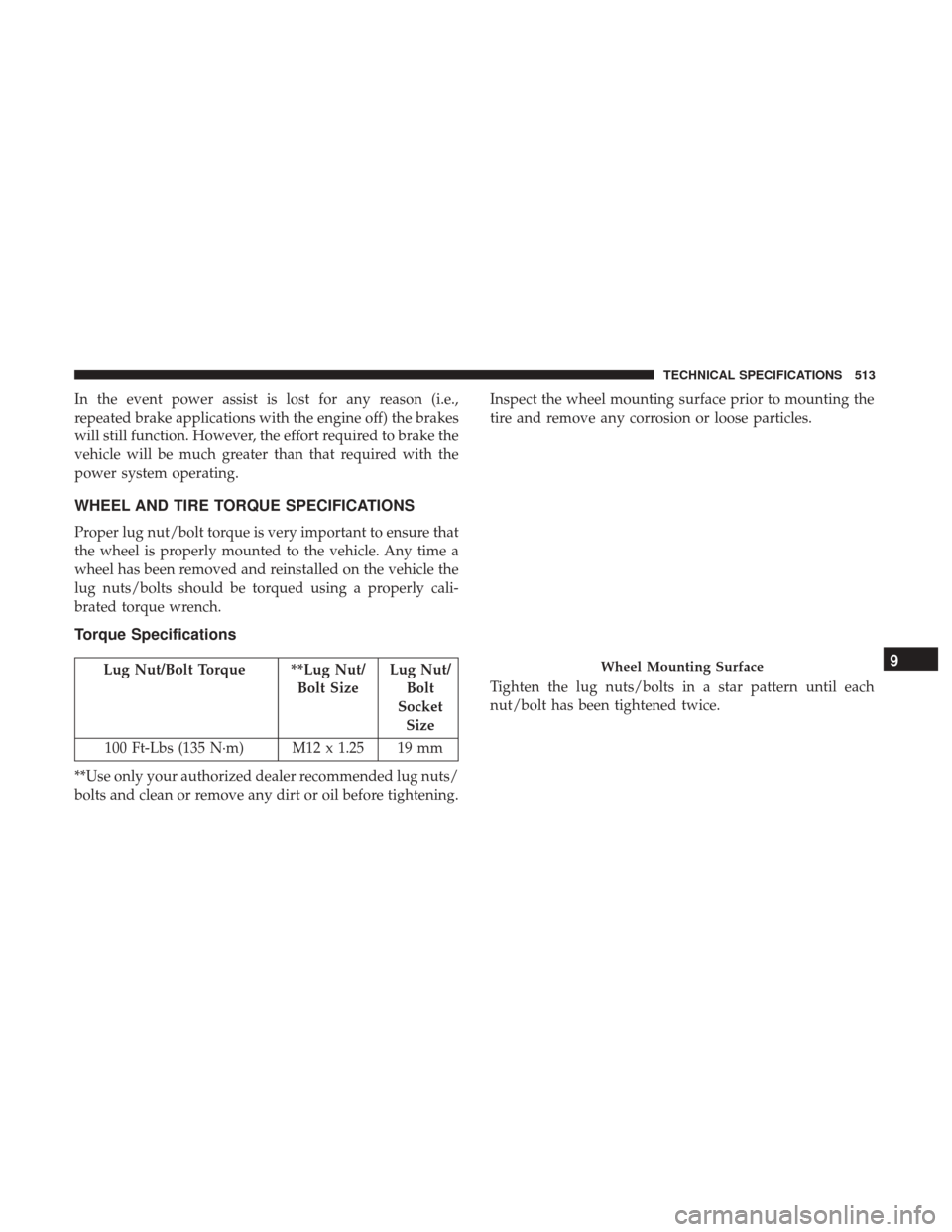
WHEEL AND TIRE TORQUE SPECIFICATIONS
Proper lug nut/bolt torque is very important to ensure that
the wheel is properly mounted to the vehicle. Any time a
wheel has been removed and reinstalled on the vehicle the
lug nuts/bolts should be torqued using a properly cali-
brated torque wrench.
Torque Specifications
Lug Nut/Bolt Torque **Lug Nut/Bolt SizeLug Nut/
Bolt
Socket Size
100 Ft-Lbs (135 N·m) M12 x 1.25 19 mm
**Use only your authorized dealer recommended lug nuts/
bolts and clean or remove any dirt or oil before tightening. Inspect the wheel mounting surface prior to mounting the
tire and remove any corrosion or loose particles.
Tighten the lug nuts/bolts in a star pattern until each
nut/bolt has been tightened twice.Wheel Mounting Surface9
TECHNICAL SPECIFICATIONS 513
Page 516 of 615

After 25 miles (40 km) check the lug nut/bolt torque to be
sure that all the lug nuts/bolts are properly seated against
the wheel.
WARNING!
To avoid the risk of forcing the vehicle off the jack, do
not tighten the lug nuts fully until the vehicle has been
lowered. Failure to follow this warning may result in
personal injury.
FUEL REQUIREMENTS
2.4L and 3.2L EnginesThese engines are designed to meet all
emissions regulations and provide opti-
mum fuel economy and performance
when using high quality unleaded
“Regular” gasoline having a posted oc-
tane number of 87 as specified by the
(R+M)/2 method. The use of higher
octane “Premium” gasoline is not required, as it will not
provide any benefit over “Regular” gasoline in these
engines.
While operating on gasoline with an octane number of 87,
hearing a light knocking sound from the engine is not a
cause for concern. However, if the engine is heard making
a heavy knocking sound, see your dealer immediately. Use
of gasoline with an octane number lower than 87 can cause
engine failure and may void or not be covered by the New
Vehicle Limited Warranty.
Poor quality gasoline can cause problems such as hard
starting, stalling, and hesitations. If you experience these
symptoms, try another brand of gasoline before consider-
ing service for the vehicle.
Torque Patterns
514 TECHNICAL SPECIFICATIONS