Page 522 of 569
Maintenance
74
7
DescriptionFuse ratingProtected Component
MULTI
FUSE
MDPS80AMDPS Unit
2 B+60ASmart Junction Box (IPS 1 (4CH), IPS 2 (1CH), IPS 5 (1CH), Fuse - SUNROOF 1, P/SEAT
PASS, P/SEAT DRV), RR A/CON
BLOWER40ABlower Relay
RR HTD40ARear Defogger Relay
ABS140AESC Module, Multipurpose Check Connector
ABS240AESC Module
C/FAN60ACooling Fan Relay
3 B+60ASmart Junction Box (Fuse - MODULE 1, SMART KEY 4, SUNROOF 2, SMART KEY 1, Leak
Current Autocut Device)
FUSE
4 B+50ASmart Junction Box (IPS 3 (4CH), IPS 6 (2CH), Fuse - F/LID, STOP LAMP, DR LOCK, BRAKE
SWITCH), FUEL LID
ECU40AECU Box
IG140AW/O Smart Key : Ignition Switch, With Smart Key - ACC Relay, IG1 Relay
IG240AStart Relay, IG2 Relay, W/O Smart Key : Ignition Switch
TRAILER30ATrailer Power Outlet
1 B+50ASmart Junction Box (Fuse - S/HEATER RR, S/HEATER FRT, P/WDW RH, P/WDW LH)
HORN15AHorn Relay
DEICER15AFront Deicer Relay
POWER OUTLET25APower Outlet Relay
AC INVERTER30AAC Inverter Module
Page 523 of 569
775
Maintenance
DescriptionFuse ratingProtected Component
FUSE
POWER TAILGATE30APower Tail Gate Module
IDB15AIDB Module
4WD20A4WD ECM
AMS10ABattery Sensor
AMS (WIPER)10ABCM, PCM
WIPER FRT25AWiper LO Relay, Front Wiper Motor
B/UP LAMP10AA/T - Rear Combination Lamp (IN) LH/RH, Electro Chromic Mirror, Audio, A/V & Navigation
Head Unit
ABS37.5AESC Module
5 SENSOR7.5APCM
TCU15AA/T : Transaxle Range Switch
F/PUMP15AFuel Pump Relay
1 ECU 15APCM
2 ECU10AIDB Module
3 SENSOR10AFuel Pump Relay
IGN COIL20ACondenser, Ignition Coil #1/#2/#3/#4
2 SENSOR10APurge Control Solenoid Valve, Variable Intake Solenoid Valve(G4KJ), Oil Control Valve #1/#2
1 SENSOR15AOxygen sensor(#1/#2/#3/#4), PCM, Oxygen Sensor(Down), E/R Fuse & Relay Box (Cooling
Fan Relay)
B/A HORN10ABurgl Aralarm Horn Relay
Page 526 of 569

Maintenance
78
7
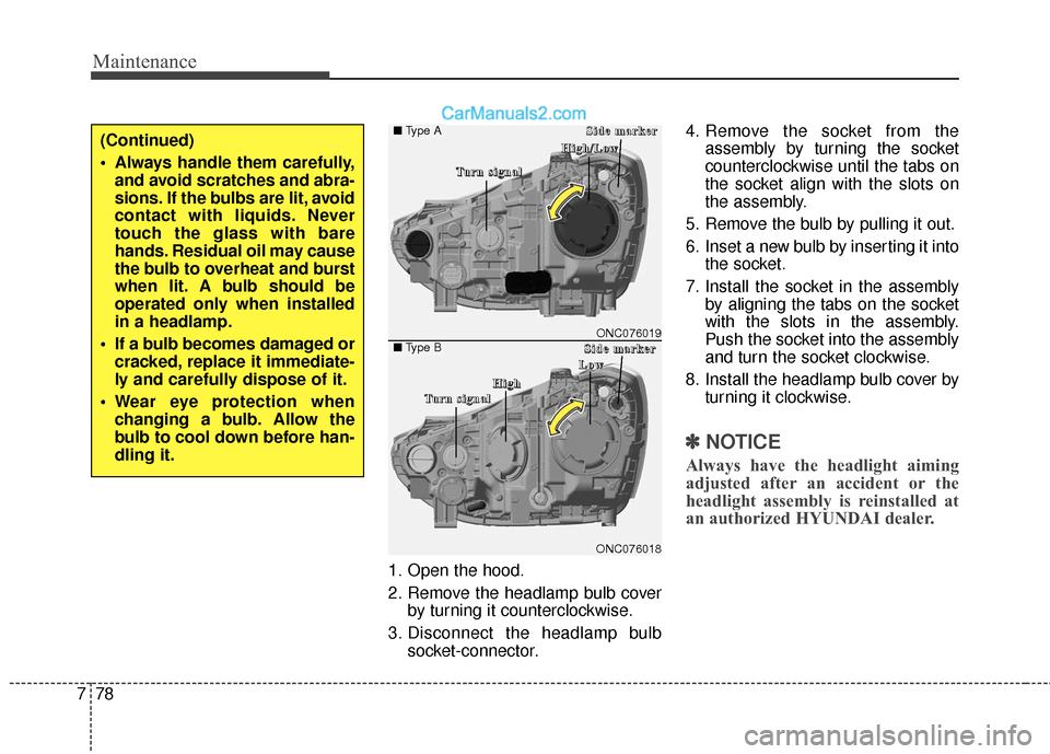
1. Open the hood.
2. Remove the headlamp bulb cover
by turning it counterclockwise.
3. Disconnect the headlamp bulb socket-connector. 4. Remove the socket from the
assembly by turning the socket
counterclockwise until the tabs on
the socket align with the slots on
the assembly.
5. Remove the bulb by pulling it out.
6. Inset a new bulb by inserting it into the socket.
7. Install the socket in the assembly by aligning the tabs on the socket
with the slots in the assembly.
Push the socket into the assembly
and turn the socket clockwise.
8. Install the headlamp bulb cover by turning it clockwise.
✽ ✽NOTICE
Always have the headlight aiming
adjusted after an accident or the
headlight assembly is reinstalled at
an authorized HYUNDAI dealer.
(Continued)
Always handle them carefully,
and avoid scratches and abra-
sions. If the bulbs are lit, avoid
contact with liquids. Never
touch the glass with bare
hands. Residual oil may cause
the bulb to overheat and burst
when lit. A bulb should be
operated only when installed
in a headlamp.
If a bulb becomes damaged or cracked, replace it immediate-
ly and carefully dispose of it.
Wear eye protection when changing a bulb. Allow the
bulb to cool down before han-
dling it.
ONC076018
■ Type A
■Type BONC076019
T
T
T
T
u
u
u
u
r
r
r
r
n
n
n
n
s
s
s
s
i
i
i
i
g
g
g
g
n
n
n
n
a
a
a
a
l
l
l
lS
S
S
S
i
i
i
i
d
d
d
d
e
e
e
e
m
m
m
m
a
a
a
a
r
r
r
r
k
k
k
k
e
e
e
e
r
r
r
r
T
T
T
T
u
u
u
u
r
r
r
r
n
n
n
n
s
s
s
s
i
i
i
i
g
g
g
g
n
n
n
n
a
a
a
a
l
l
l
l
H
H
H
H
i
i
i
i
g
g
g
g
h
h
h
h
/
/
/
/
L
L
L
L
o
o
o
o
w
w
w
w
S
S
S
S
i
i
i
i
d
d
d
d
e
e
e
e
m
m
m
m
a
a
a
a
r
r
r
r
k
k
k
k
e
e
e
e
r
r
r
r
H
H
H
H
i
i
i
i
g
g
g
g
h
h
h
h
L
L
L
L
o
o
o
o
w
w
w
w
Page 528 of 569

Maintenance
80
7
Turn signal lamp/
Side marker lamp (bulb type)
1. Remove the socket from the assembly by turning the socket
counterclockwise until the tabs on
the socket align with the slots on
the assembly.
2. Remove the bulb from the socket by pressing it in and rotating it
counterclockwise until the tabs on
the bulb align with the slots in the
socket. Pull the bulb out of the
socket
3. Insert a new bulb by inserting it into the socket and rotating it until
it locks into place.
4. Install the socket in the assembly by aligning the tabs on the socket
with the slots in the assembly.
Push the socket into the assembly
and turn the socket clockwise.
Daytime running lamp (DRL)/
Position lamp/Fog lamp (LED type)
If the LED lamp does not operate,
have the system checked by an
authorized HYUNDAI dealer.
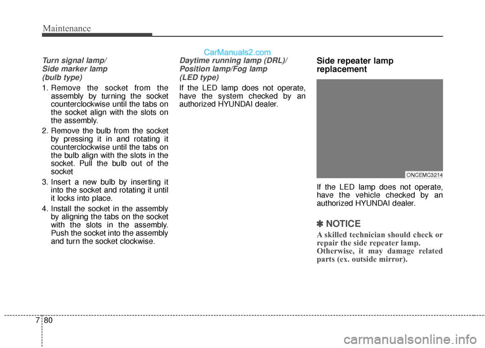
Side repeater lamp
replacement
If the LED lamp does not operate,
have the vehicle checked by an
authorized HYUNDAI dealer.
✽ ✽ NOTICE
A skilled technician should check or
repair the side repeater lamp.
Otherwise, it may damage related
parts (ex. outside mirror).
ONCEMC3214
Page 530 of 569
Maintenance
82
7
5. Remove the socket from the
assembly by turning the socket
counterclockwise until the tabs on
the socket align with the slots on
the assembly. 6. Remove the bulb from the socket
by pressing it in and rotating it
counterclockwise until the tabs on
the bulb align with the slots in the
socket. Pull the bulb out of the
socket. (Side marker : Remove the
bulb from the socket by pulling it
out)
7. Insert a new bulb by inserting it into the socket and rotating it until
it locks into place.
8. Install the socket in the assembly by aligning the tabs on the socket
with the slots in the assembly.
Push the socket into the assembly
and turn the socket clockwise.
9. Reinstall the lamp assembly to the body of the vehicle.
Inside lamp
1. Open the liftgate (tailgate).
2. Remove the service cover using aflat-blade screwdriver.
OANNMC2036
ODM076104L
ODM076103L
■
Type A
■ Type B
Page 531 of 569
783
Maintenance
3. Remove the socket from theassembly by turning the socket
counterclockwise until the tabs on
the socket align with the slots on
the assembly.
4. Remove the bulb from the socket by pressing it in and rotating it
counterclockwise until the tabs on
the bulb align with the slots in the
socket. Pull the bulb out of the
socket. (Back-up lamp : Remove
the bulb from the socket by pulling
it out) 5. Insert a new bulb by inserting it
into the socket and rotating it until
it locks into place.
6. Install the socket in the assembly by aligning the tabs on the socket
with the slots in the assembly.
Push the socket into the assembly
and turn the socket clockwise.
7. Install the service cover by putting it into the service hole.
Stop/tail lamp (LED type)
If the LED lamp does not operate,
have the vehicle checked by an
authorized HYUNDAI dealer.
ONCNMC2039
Page 534 of 569
Maintenance
86
7
Interior lamp bulb replacement
1. Using a flat-blade screwdriver,
gently pry the lens from the interi-
or lamp housing.
2. Remove the bulb by pulling it straight out.
3. Install a new bulb in the socket.
4. Align the lens tabs with the interi- or lamp housing notches and snap
the lens into place.
■Map lamp
OXM079044/ODM072041/ODM072043
■Glove box lamp (if equipped)
■Luggage room lamp (if equipped)
■Room lamp
ODM072040/ODM072042/ODM072052■Type A
■Type B
WARNING
Prior to working on the Interior
Lamps, ensure that the "OFF"
button is depressed to avoid
burning your fingers or receiv-
ing an electric shock.
CAUTION
Use care not to dirty or damage
lens, lens tab, and plastic hous-ings.
■ Sunvisor lamp
Page 543 of 569

795
Maintenance
2. Evaporative emission con-trol (including ORVR:
Onboard Refueling Vapor
Recovery) system
The Evaporative Emission Control
System is designed to prevent fuel
vapors from escaping into the atmos-
phere.
(The ORVR system is designed to
allow the vapors from the fuel tank to
be loaded into a canister while refu-
eling at the gas station, preventing
the escape of fuel vapors into the
atmosphere.)
Canister
Fuel vapors generated inside the fuel
tank are absorbed and stored in the
onboard canister. When the engine is
running, the fuel vapors absorbed in
the canister are drawn into the surge
tank through the purge control sole-
noid valve.
Purge Control Solenoid Valve
(PCSV)
The purge control solenoid valve is
controlled by the Engine Control
Module (ECM); when the engine
coolant temperature is low during
idling, the PCSV closes so that evap-
orated fuel is not taken into the
engine. After the engine warms-up
during ordinary driving, the PCSV
opens to introduce evaporated fuel to
the engine.
3. Exhaust emission control system
The Exhaust Emission Control
System is a highly effective system
which controls exhaust emissions
while maintaining good vehicle per-
formance.
Vehicle modifications
This vehicle should not be modified.
Modification of your vehicle could
affect its performance, safety or
durability and may even violate gov-
ernmental safety and emissions reg-
ulations.
In addition, damage or performance
problems resulting from any modifi-
cation may not be covered under
warranty.
If you use unauthorized electronic
devices, it may cause the vehicle to
operate abnormally, wire damage,
battery discharge and fire. For your
safety, do not use unauthorized
electronic devices.