2017 Hyundai Ioniq Electric stop start
[x] Cancel search: stop startPage 421 of 582
5-82
Driving your vehicle
Cancelled automatically
The driver's door is opened.
The vehicle is shifted to N(Neutral), R (Reverse) or P (Park).
The EPB (Electronic Parking Brake) is applied.
The vehicle speed is over 190 km/h (120 mph).
The vehicle stops on a steep incline.
The ESC (Electronic Stability Control), TCS (Traction Control
System) or ABS is operating.
The ESC is turned off.
The sensor or the cover is dirty or blocked with foreign matter.
The vehicle is stopped for more than 5 minutes.
The vehicle stops and goes repeat- edly for a long period of time.
The driver starts driving by pushing the toggle switch up (RES+)/down
(SET-) or depressing the accelera-
tor pedal, approximately 3 minutes
after the vehicle is stopped by the
Smart Cruise Control System with
no other vehicle ahead. The driver starts driving by pushing
the toggle switch up (RES+)/down
(SET-) or depressing the accelera-
tor pedal, after stopping the vehicle
with a vehicle stopped far away infront.
The accelerator pedal is continu- ously depressed for more than one
minute.
The AEB is activated.
Each of these actions will cancel
the Smart Cruise Control opera-
tion. The Set Speed and Vehicle-to-
Vehicle Distance on the LCD dis-
play will go off.
In a condition the Smart Cruise Control is cancelled automatically,
the Smart Cruise Control will not
resume even though the RES+ or
SET- toggle switch is pushed.
Information
If the Smart Cruise Control is cancelled
by other than the reasons mentioned,
we recommend that the system be
checked by an authorized HYUNDAI
dealer.
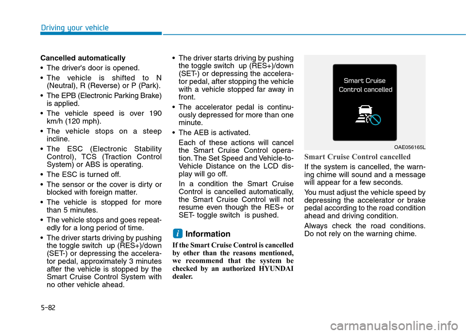
Smart Cruise Control cancelled
If the system is cancelled, the warn- ing chime will sound and a message
will appear for a few seconds.
You must adjust the vehicle speed by
depressing the accelerator or brakepedal according to the road condition
ahead and driving condition.
Always check the road conditions.
Do not rely on the warning chime.
i
OAE056165L
Page 425 of 582

5-86
Driving your vehicle
In traffic situation
Use switch or pedal to accelerate
In traffic, your vehicle will stop if thevehicle ahead of you stops. Also, if
the vehicle ahead of you starts
moving, your vehicle will start as
well. However, if the vehicle stops
for more than 3 seconds, you must
depress the accelerator pedal or
push up the toggle switch (RES+)
to start driving. If you push the advanced smart
cruise control toggle switch (RES+
or SET-) while Auto Hold and
advanced smart cruise control is
operating the Auto Hold will be
released regardless of accelerator
pedal operation and the vehicle will
start to move. The AUTO HOLD
indicator changes from green to
white.
Sensor to detect distance to
the vehicle ahead
The Smart Cruise Control uses a
sensor to detect distance to the vehi-cle ahead.
OAEE056011
OAEE046473L
Page 443 of 582
6-2
The hazard warning flasher serves as
a warning to other drivers to exercise
extreme caution when approaching,
overtaking, or passing your vehicle.
It should be used whenever emer- gency repairs are being made or
when the vehicle is stopped near the
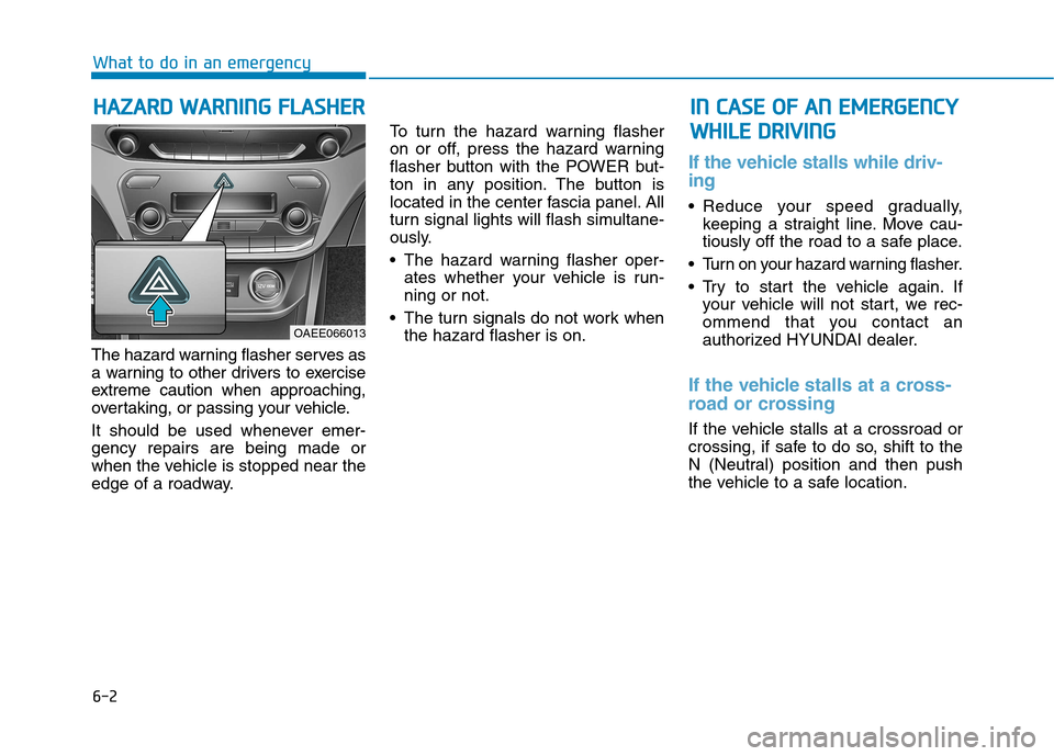
edge of a roadway. To turn the hazard warning flasher
on or off, press the hazard warning
flasher button with the POWER but-
ton in any position. The button is
located in the center fascia panel. All
turn signal lights will flash simultane-
ously.
• The hazard warning flasher oper-
ates whether your vehicle is run- ning or not.
The turn signals do not work when the hazard flasher is on.
If the vehicle stalls while driv- ing
Reduce your speed gradually,keeping a straight line. Move cau-
tiously off the road to a safe place.
Turn on your hazard warning flasher.
Try to start the vehicle again. If your vehicle will not start, we rec-
ommend that you contact an
authorized HYUNDAI dealer.
If the vehicle stalls at a cross-
road or crossing
If the vehicle stalls at a crossroad or
crossing, if safe to do so, shift to the
N (Neutral) position and then push
the vehicle to a safe location.
HH AAZZAA RRDD WW AARRNN IINN GG FF LLAA SSHH EERR
What to do in an emergency
IINN CC AA SSEE OO FF AA NN EE MM EERR GG EENN CCYY
W
W HHIILL EE DD RRIIVV IINN GG
OAEE066013
Page 446 of 582
6-5
What to do in an emergency
To prevent damage to your vehicle:
• Only use a 12-volt power supply(battery or jumper system) to
jump start your vehicle.
Do not attempt to jump start your vehicle by push-starting.
Information An inappropriately disposedbattery can be harmful to the
environment and human
health. Dispose the battery
according to your local law(s)
or regulations.
i
NOTICE
6
(Continued)
Batteries contain sulfu-
ric acid which is highly
corrosive. Do not allow
acid to contact your
eyes, skin or clothing.
If acid gets into your eyes, flush
your eyes with clean water for at
least 15 minutes and get imme-
diate medical attention. If acid
gets on your skin, thoroughly
wash the area. If you feel pain or
a burning sensation, get med-
ical attention immediately.
When lifting a plastic-cased
battery, excessive pressure
on the case may cause battery
acid to leak. Lift with a battery
carrier or with your hands on
opposite corners.
Do not attempt to jump start
your vehicle if your battery is
frozen.
(Continued)
(Continued)
NEVER attempt to recharge
the battery when the vehicle’s
battery cables are connected
to the battery.
The electrical ignition system
works with high voltage.
NEVER touch these compo-nents with the engine running
or when the Engine Start/Stop
button is in the ON position.
Do not allow the (+) and (-)
jumper cables to touch. It maycause sparks.
The battery may rupture or
explode when you jump start
with a low or frozen battery.
Pb
Page 450 of 582
6-9
What to do in an emergency
6
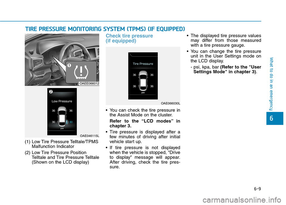
(1) Low Tire Pressure Telltale/TPMSMalfunction Indicator
(2) Low Tire Pressure Position Telltale and Tire Pressure Telltale
(Shown on the LCD display)
Check tire pressure (if equipped)
You can check the tire pressure inthe Assist Mode on the cluster.
Refer to the “LCD modes” in chapter 3.
Tire pressure is displayed after a few minutes of driving after initial
vehicle start up.
If tire pressure is not displayed when the vehicle is stopped, "Drive
to display" message will appear.
After driving, check the tire pres-
sure. The displayed tire pressure values
may differ from those measured
with a tire pressure gauge.
You can change the tire pressure unit in the User Settings mode on
the LCD display. - psi, kpa, bar (Refer to the "User
Settings Mode" in chapter 3) .
TTIIRR EE PP RR EESSSS UU RREE MM OONNIITT OO RRIINN GG SS YY SSTT EEMM (( TT PP MM SS)) (( IIFF EE QQ UUIIPP PPEEDD ))
OAEE066012
OAE046115L
OAE066030L
Page 451 of 582

6-10
What to do in an emergency
Tire pressure monitoring sys- tem
Each tire should be checked monthly when cold and inflated to the inflation
pressure recommended by the vehi-
cle manufacturer on the vehicle plac-
ard or tire inflation pressure label. (If
your vehicle has tires of a different
size than the size indicated on the
vehicle placard or tire inflation pres-
sure label, you should determine the
proper tire inflation pressure for
those tires.)As an added safety feature, your
vehicle has been equipped with a tire
pressure monitoring system (TPMS)
that illuminates a low tire pressure
telltale when one or more of yourtires is significantly under-inflated.
Accordingly, when the low tire pres-
sure telltale illuminates, you should
stop and check your tires as soon as
possible, and inflate them to the
proper pressure. Driving on a signifi-cantly under-inflated tire causes the
tire to overheat and can lead to tire
failure. Under-inflation also reduces fuel effi-
ciency and tire tread life, and may
affect the vehicle’s handling and
stopping ability.
Please note that the TPMS is not a
substitute for proper tire mainte-
nance, and it is the driver’s responsi-bility to maintain correct tire pres-
sure, even if under-inflation has not
reached the level to trigger illumina-
tion of the TPMS low tire pressure
telltale.Your vehicle has also been equipped
with a TPMS malfunction indicator toindicate when the system is not
operating properly. The TPMS mal-function indicator is combined with
the low tire pressure telltale. Whenthe system detects a malfunction,
the telltale will flash for approximate-
ly one minute and then remain con-
tinuously illuminated. This sequence
will continue upon subsequent vehi-
cle start-ups as long as the malfunc-
tion exists. When the malfunction indicator is illu-
minated, the system may not be able
to detect or signal low tire pressure
as intended. TPMS malfunctions may
occur for a variety of reasons, includ-ing the installation of replacement or
alternate tires or wheels on the vehi-
cle that prevent the TPMS from func-
tioning properly.
Always check the TPMS malfunction telltale after replacing one or more
tires or wheels on your vehicle toensure that the replacement or alter-
nate tires and wheels allow the TPMS
to continue to function properly.
Over-inflation or under-inflation
can reduce tire life, adversely
affect vehicle handling, and
lead to sudden tire failure that
may cause loss of vehicle con-
trol resulting in an accident.
WARNING
Page 484 of 582
7-18
Maintenance
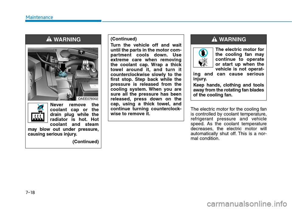
The electric motor for the cooling fan
is controlled by coolant temperature,
refrigerant pressure and vehicle
speed. As the coolant temperature
decreases, the electric motor will
automatically shut off. This is a nor-mal condition.
Never remove the
coolant cap or thedrain plug while the
radiator is hot. Hotcoolant and steam
may blow out under pressure,
causing serious injury.
(Continued)
WARNING
OAEE076002 The electric motor for
the cooling fan may
continue to operate
or start up when the
vehicle is not operat-
ing and can cause serious
injury.
Keep hands, clothing and tools
away from the rotating fan bladesof the cooling fan.
WARNING (Continued)
Turn the vehicle off and wait
until the parts in the motor com-
partment cools down. Use
extreme care when removing
the coolant cap. Wrap a thick
towel around it, and turn it
counterclockwise slowly to the
first stop. Step back while the
pressure is released from the
cooling system. When you aresure all the pressure has been
released, press down on the
cap, using a thick towel, and
continue turning counterclock-
wise to remove it.
Page 515 of 582

7-49
7
Maintenance
Fuse NameSymbolFuse RatingCircuit Protected
Heated Steering15ABCM
Sunroof20ASunroof Motor
Power WindowRight-handRH25APower Window (RH) Relay, Passenger Power Window Switch, Driver Safety Power Window
Power Window Left-handLH25APower Window (LH) Relay, Driver Power Window Switch,
Passenger Safety Power Window Module
Button Start 227.5AImmobilizer Module, Smart Key Control Module, Start/Stop Button Switch
Brake SwitchBRAKE
S WITCH7.5AStop Lamp Switch, Smart Key Control Module
OBC10AOBC
Air conditioner7.5AIonizer, A/C Control Module, Electronic A/C Compressor, E/R Junction Block
Washer15AMultifunction Switch
Seat Heater RearRR25ARear Seat Warmer Module
Charger10ACCM Unit(for Europe), Normal Charging Connector Lamp(except Europe),
ICM Relay Box (Charging Connector Lock/Unlock Relay)
Power Seat DriverDRV30ADriver Seat Manual Switch, Driver IMS Module
Instrument panel fuse panel