2017 HYUNDAI ELANTRA SE relay
[x] Cancel search: relayPage 19 of 586

F19F19
Radial-Ply Tires ...............................................................7-58
Low Aspect Ratio Tires..................................................7-58
Fuses ......................................................................7-\
60
Instrument Panel Fuse Replacement..........................7-61
Engine Compartment Panel Fuse Replacement.......7-63
Fuse/Relay Panel Description ......................................7-66
Light bulbs.............................................................7-72
Headlamp, Parking lamp, Turn signal lamp and
side marker .......................................................................7\
-73
Side repeater lamp replacement .................................7-82
Rear combination light bulb replacement .................7-82
High mounted stop light replacement........................7-86
License plate light bulb replacement .........................7-87
Interior light bulb replacement ....................................7-88
Appearance care ..................................................7-89
Exterior Care ....................................................................7-89\
Interior Care .....................................................................7-9\
5
Emission control system .....................................7-96
1. Crankcase Emission Control System......................7-96
2. Evaporative Emission Control System Including Onboard Refueling Vapor Recovery (ORVR) .......7-96
3. Exhaust Emission Control System ..........................7-97
California perchlorate notice ...........................7-100 Dimensions ..............................................................8-2
Engine ......................................................................8-\
2
Bulb Wattage ..........................................................8-3
Tires and Wheels ...................................................8-5
Volume and Weight ................................................8-6
Air Conditioning System........................................8-6
Recommended Lubricants and Capacities ..........8-7
Recommended SAE Viscosity Number .........................8-9
Vehicle Identification Number (VIN) .................8-10
Vehicle Certification Label .................................8-10
Tire Specification and Pressure Label .............8-11
Engine Number .....................................................8-11
Refrigerant Label .................................................8-11
Consumer Information .........................................8-12
Reporting Safety Defects ...................................8-13
8Specifications, Consumer information and
Reporting safety defects
Page 116 of 586
3-22
Convenient features of your vehicle
S
ST
T E
EE
ER
R I
IN
N G
G
W
W H
HE
EE
EL
L
Electric Power Steering (EPS)
The system assists you with steering
the vehicle. If the engine is turned off
or if the power steering system
becomes inoperative, you may still
steer the vehicle, but it will require
increased steering effort.
Should you notice any change in the
effort required to steer during normal
vehicle operation, have the system
checked by an authorized HYUNDAI
dealer.
Information
The following symptoms may occur
during normal vehicle operation:
• The steering effort may be high
immediately after placing the igni-
tion switch in the ON position.
This happens as the system per-
forms the EPS system diagnostics.
When the diagnostics is completed,
the steering wheel will return to its
normal condition.
• A click noise may be heard from the EPS relay after the ignition switch is
in the ON or OFF position.
• Motor noise may be heard when the vehicle is at a stop or at a low driv-
ing speed.
• When you operate the steering wheel in low temperature, abnormal
noise may occur. If temperature
rises, the noise will disappear. This
is a normal condition.
(Continued)(Continued)
• When an error is detected from the
EPS, the assistant function of steer-
ing effort will not be activated in
order to prevent fatal accidents.
Dashboard warning lights may be
on or the steering effort may be
high. When the following symptoms
occur, immediately drive the vehicle
to a safe area and check it.
i
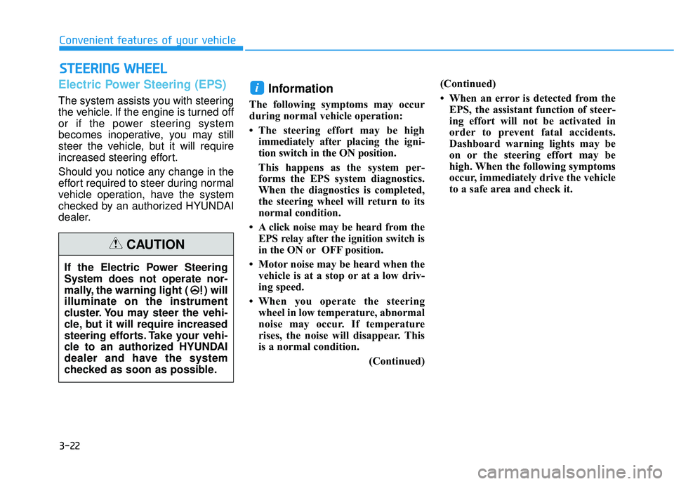
If the Electric Power Steering
System does not operate nor-
mally, the warning light ( ) will
illuminate on the instrument
cluster. You may steer the vehi-
cle, but it will require increased
steering efforts. Take your vehi-
cle to an authorized HYUNDAI
dealer and have the system
checked as soon as possible.
CAUTION
Page 462 of 586
7
Fuses ......................................................................7-\
60
Instrument Panel Fuse Replacement..........................7-61
Engine Compartment Panel Fuse Replacement.......7-63
Fuse/Relay Panel Description ......................................7-66
Light bulbs.............................................................7-72
Headlamp, Parking lamp, Turn signal lamp and
side marker .......................................................................7\
-73
Side repeater lamp replacement .................................7-82
Rear combination light bulb replacement .................7-82
High mounted stop light replacement........................7-86
License plate light bulb replacement .........................7-87
Interior light bulb replacement ....................................7-88
Appearance care ..................................................7-89
Exterior Care ....................................................................7-89\
Interior Care .....................................................................7-9\
5
Emission control system .....................................7-96
1. Crankcase Emission Control System......................7-96
2. Evaporative Emission Control System Including Onboard Refueling Vapor Recovery (ORVR) .......7-96
3. Exhaust Emission Control System ..........................7-97
California perchlorate notice ...........................7-100
Page 526 of 586
7-66
Maintenance
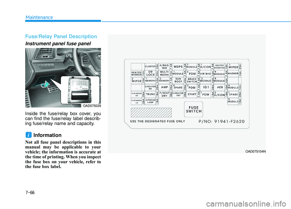
Fuse/Relay Panel Description
Instrument panel fuse panel
Inside the fuse/relay box cover, you
can find the fuse/relay label describ-
ing fuse/relay name and capacity.
Information
Not all fuse panel descriptions in this
manual may be applicable to your
vehicle; the information is accurate at
the time of printing. When you inspect
the fuse box on your vehicle, refer to
the fuse box label.
i
OAD075029
OAD075104N
Page 527 of 586
7-67
7
Maintenance
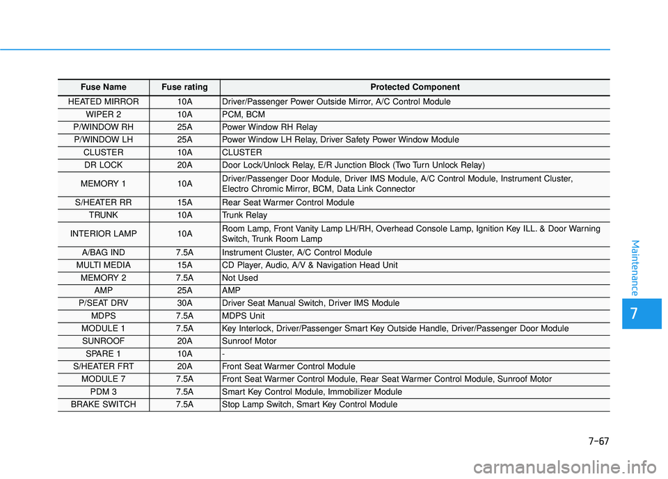
Fuse Name Fuse rating Protected Component
HEATED MIRROR 10A Driver/Passenger Power Outside Mirror, A/C Control Module
WIPER 2 10A PCM, BCM
P/WINDOW RH 25A Power Window RH Relay
P/WINDOW LH 25A Power Window LH Relay, Driver Safety Power Window Module
CLUSTER 10A CLUSTER
DR LOCK 20A Door Lock/Unlock Relay, E/R Junction Block (Two Turn Unlock Relay)
MEMORY 1 10A Driver/Passenger Door Module, Driver IMS Module, A/C Control Module, Instrument Cluster,
Electro Chromic Mirror, BCM, Data Link Connector
S/HEATER RR 15A Rear Seat Warmer Control Module
TRUNK 10A Trunk Relay
INTERIOR LAMP 10A Room Lamp, Front Vanity Lamp LH/RH, Overhead Console Lamp, Ignition Key ILL. & Door Warning
Switch, Trunk Room Lamp
A/BAG IND 7.5A Instrument Cluster, A/C Control Module
MULTI MEDIA 15A CD Player, Audio, A/V & Navigation Head Unit
MEMORY 2 7.5A Not Used
AMP 25A AMP
P/SEAT DRV 30A Driver Seat Manual Switch, Driver IMS Module
MDPS 7.5A MDPS Unit
MODULE 1 7.5A Key Interlock, Driver/Passenger Smart Key Outside Handle, Driver/Passenger Door Module
SUNROOF 20A Sunroof Motor
SPARE 1 10A -
S/HEATER FRT 20A Front Seat Warmer Control Module
MODULE 7 7.5A Front Seat Warmer Control Module, Rear Seat Warmer Control Module, Sunroof Motor
PDM 3 7.5A Smart Key Control Module, Immobilizer Module
BRAKE SWITCH 7.5A Stop Lamp Switch, Smart Key Control Module
Page 528 of 586
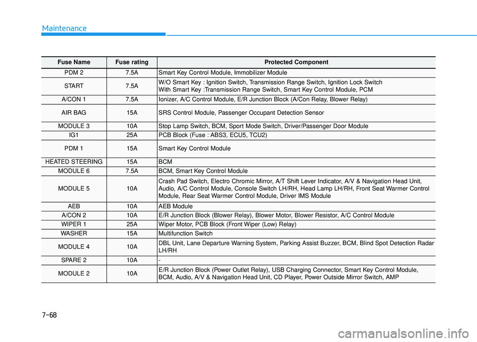
7-68
Maintenance
Fuse Name Fuse rating Protected Component
PDM 2 7.5A Smart Key Control Module, Immobilizer Module
START 7.5A W/O Smart Key : Ignition Switch, Transmission Range Switch, Ignition Lock Switch
With Smart Key :Transmission Range Switch, Smart Key Control Module, PCM
A/CON 1 7.5A Ionizer, A/C Control Module, E/R Junction Block (A/Con Relay, Blower Relay)
AIR BAG 15A SRS Control Module, Passenger Occupant Detection Sensor
MODULE 3 10A Stop Lamp Switch, BCM, Sport Mode Switch, Driver/Passenger Door Module
IG1 25A PCB Block (Fuse : ABS3, ECU5, TCU2)
PDM 1 15A Smart Key Control Module
HEATED STEERING 15A BCM
MODULE 6 7.5A BCM, Smart Key Control Module
MODULE 5 10A Crash Pad Switch, Electro Chromic Mirror, A/T Shift Lever Indicator, A/V & Navigation Head Unit,
Audio, A/C Control Module, Console Switch LH/RH, Head Lamp LH/RH, Front Seat Warmer Control
Module, Rear Seat Warmer Control Module, Driver IMS Module
AEB 10A AEB Module
A/CON 2 10A E/R Junction Block (Blower Relay), Blower Motor, Blower Resistor, A/C Control Module
WIPER 1 25A Wiper Motor, PCB Block (Front Wiper (Low) Relay)
WASHER 15A Multifunction Switch
MODULE 4 10A DBL Unit, Lane Departure Warning System, Parking Assist Buzzer, BCM, Blind Spot Detection Radar
LH/RH
SPARE 2 10A -
MODULE 2 10A E/R Junction Block (Power Outlet Relay), USB Charging Connector, Smart Key Control Module,
BCM, Audio, A/V & Navigation Head Unit, CD Player, Power Outside Mirror Switch, AMP
Page 529 of 586

7-69
7
Maintenance
Engine compartment fuse panel
Inside the fuse/relay box cover, you
can find the fuse/relay label describ-
ing fuse/relay name and capacity.
Information
Not all fuse panel descriptions in this
manual may be applicable to your
vehicle; the information is accurate at
the time of printing. When you inspect
the fuse panel in your vehicle, refer to
the fuse panel label.
i
OAD075027
OAD075105N
Page 530 of 586
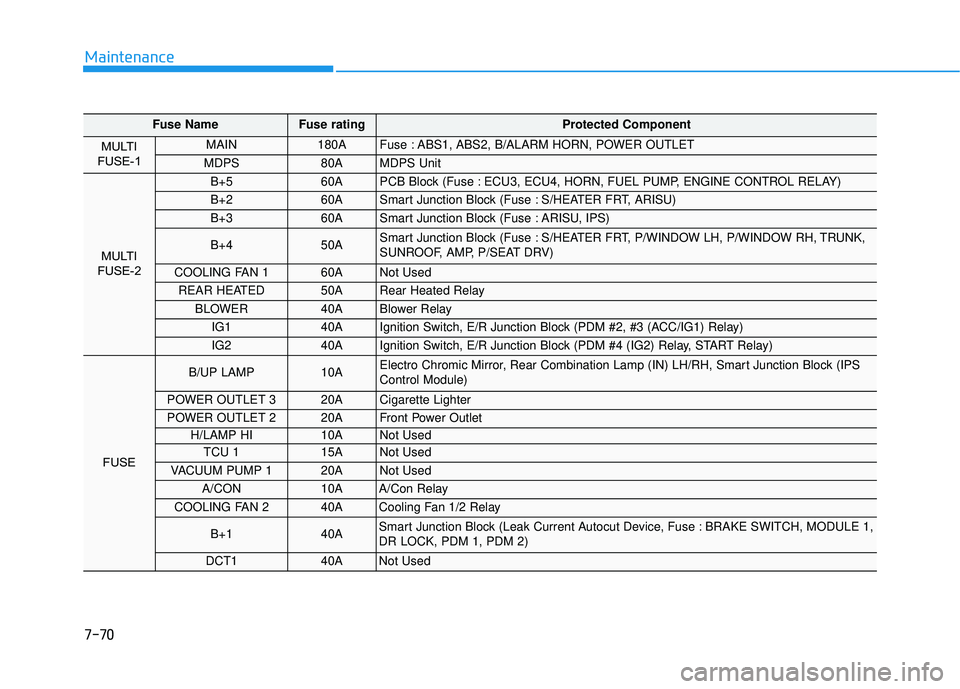
7-70
Maintenance
Fuse NameFuse rating Protected Component
MULTI
FUSE-1 MAIN 180A Fuse : ABS1, ABS2, B/ALARM HORN, POWER OUTLET
MDPS 80A MDPS Unit
MULTI
FUSE-2
B+5 60A PCB Block (Fuse : ECU3, ECU4, HORN, FUEL PUMP, ENGINE CONTROL RELAY)
B+2 60A Smart Junction Block (Fuse : S/HEATER FRT, ARISU)
B+3 60A Smart Junction Block (Fuse : ARISU, IPS)
B+4 50A Smart Junction Block (Fuse : S/HEATER FRT, P/WINDOW LH, P/WINDOW RH, TRUNK,
SUNROOF, AMP, P/SEAT DRV)
COOLING FAN 1 60A Not Used
REAR HEATED 50A Rear Heated Relay
BLOWER 40A Blower Relay
IG1 40A Ignition Switch, E/R Junction Block (PDM #2, #3 (ACC/IG1) Relay)
IG2 40A Ignition Switch, E/R Junction Block (PDM #4 (IG2) Relay, START Relay)
FUSE
B/UP LAMP 10A Electro Chromic Mirror, Rear Combination Lamp (IN) LH/RH, Smart Junction Block (IPS
Control Module)
POWER OUTLET 3 20A Cigarette Lighter
POWER OUTLET 2 20A Front Power Outlet
H/LAMP HI 10A Not Used
TCU 1 15A Not Used
VACUUM PUMP 1 20A Not Used
A/CON 10A A/Con Relay
COOLING FAN 2 40A Cooling Fan 1/2 Relay
B+1 40A Smart Junction Block (Leak Current Autocut Device, Fuse : BRAKE SWITCH, MODULE 1,
DR LOCK, PDM 1, PDM 2)
DCT1 40A Not Used