Page 522 of 586
7-62
Maintenance
In an emergency, if you do not have
a spare fuse, use a fuse of the same
rating from a circuit you may not
need for operating the vehicle, such
as the cigarette lighter fuse.
If the headlamps or other electrical
components do not work and the
fuses are OK, check the fuse panel
in the engine compartment. If a fuse
is blown, it must be replaced with the
same rating.
Fuse switch
Always, place the fuse switch to the
ON position.
If you move the switch to the OFF
position, some items such as the
audio system and digital clock must
be reset and the smart key may not
work properly.
Information
If the fuse switch is OFF, the above
message will appear.
i
OAD075023OAD045144/OTL045155L
■ Conventional cluster ■Supervision cluster
Page 523 of 586
7-63
7
Maintenance
Always place the fuse switch inthe ON position while driving the
vehicle.
Do not move the fuse switch repeatedly. The fuse switch may
be damaged.
Engine Compartment Panel
Fuse Replacement
1. Turn the engine off.
2. Turn all other switches OFF.
3. Remove the fuse panel cover by pressing the tap and pulling up.
4. Check the removed fuse; replace it if it is blown. To remove or insert
the fuse, use the fuse puller in the
engine compartment fuse panel.
5. Push in a new fuse of the same rating, and make sure it fits tightly
in the clips. If it fits loosely, consult
an authorized HYUNDAI dealer.
NOTICE
After checking the fuse box in
the engine compartment
securely close the fuse box
cover inside the engine com-
partment, until it clicks.
If the fuse box is not closed
properly, water may leak in side,
possibly causing a malfunction
with the electrical system.
CAUTION
OAD075024
Page 524 of 586
7-64
Maintenance
Main fuse
If the main fuse is blown, it must be
removed as follows:
1. Turn off the engine.
2. Disconnect the negative batterycable.
3. Remove the fuse panel cover by pressing the tab and pulling it up.
4. Remove the nuts shown in the pic- ture above.
5. Replace the fuse with a new one of the same rating.
6. Reinstall in the reverse order of removal.
Information
If the main fuse is blown, consult an
authorized HYUNDAI dealer.
Multi fuse
If the multi fuse is blown, it must be
removed as follows:
1. Turn off the engine.
2. Disconnect the negative battery
cable.
3. Remove the fuse panel cover by pressing the tab and pulling it up.
4. Remove the nuts shown in the pic- ture above.
5. Replace the fuse with a new one of the same rating.
6. Reinstall in the reverse order of removal.
i
OAD075026OAD075025
Page 525 of 586
7-65
7
Maintenance
Information
If the multi fuse is blown, consult an
authorized HYUNDAI dealer.
Blade type fuse
Before inspecting a fuse, you should
turn OFF the engine as well as the
other electric system switches.
If a fuse is blown out, remove the
blown-out fuse and install a new fuse
of the same capacity by using the
fuse puller, which is prepared inside
the fuse box in the engine compart-
ment. A new fuse may be prepared
along with the fuse puller. However, if
not, you may temporarily select/use
a fuse of the other systems, which do
not affect the vehicle operation, such
as the audio system.
Cartridge type fuse
Before inspecting a fuse, you should
turn OFF the engine as well as the
other electric system switches.
If a fuse is blown out, remove the
blown-out fuse and install a new fuse
of the same capacity. Pay extreme
caution not to damage the blown-out
fuse while removing it.
i
OAD075054OAD075053
Page 529 of 586
7-69
7
Maintenance
Engine compartment fuse panel
Inside the fuse/relay box cover, you
can find the fuse/relay label describ-
ing fuse/relay name and capacity.
Information
Not all fuse panel descriptions in this
manual may be applicable to your
vehicle; the information is accurate at
the time of printing. When you inspect
the fuse panel in your vehicle, refer to
the fuse panel label.
i
OAD075027
OAD075105N
Page 530 of 586

7-70
Maintenance
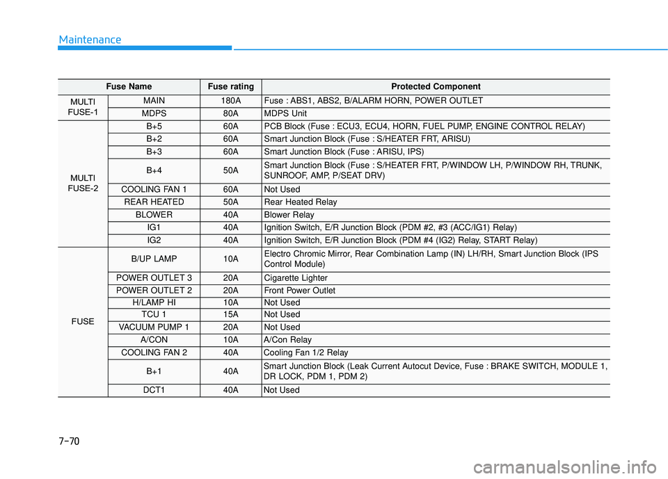
Fuse NameFuse rating Protected Component
MULTI
FUSE-1 MAIN 180A Fuse : ABS1, ABS2, B/ALARM HORN, POWER OUTLET
MDPS 80A MDPS Unit
MULTI
FUSE-2
B+5 60A PCB Block (Fuse : ECU3, ECU4, HORN, FUEL PUMP, ENGINE CONTROL RELAY)
B+2 60A Smart Junction Block (Fuse : S/HEATER FRT, ARISU)
B+3 60A Smart Junction Block (Fuse : ARISU, IPS)
B+4 50A Smart Junction Block (Fuse : S/HEATER FRT, P/WINDOW LH, P/WINDOW RH, TRUNK,
SUNROOF, AMP, P/SEAT DRV)
COOLING FAN 1 60A Not Used
REAR HEATED 50A Rear Heated Relay
BLOWER 40A Blower Relay
IG1 40A Ignition Switch, E/R Junction Block (PDM #2, #3 (ACC/IG1) Relay)
IG2 40A Ignition Switch, E/R Junction Block (PDM #4 (IG2) Relay, START Relay)
FUSE
B/UP LAMP 10A Electro Chromic Mirror, Rear Combination Lamp (IN) LH/RH, Smart Junction Block (IPS
Control Module)
POWER OUTLET 3 20A Cigarette Lighter
POWER OUTLET 2 20A Front Power Outlet
H/LAMP HI 10A Not Used
TCU 1 15A Not Used
VACUUM PUMP 1 20A Not Used
A/CON 10A A/Con Relay
COOLING FAN 2 40A Cooling Fan 1/2 Relay
B+1 40A Smart Junction Block (Leak Current Autocut Device, Fuse : BRAKE SWITCH, MODULE 1,
DR LOCK, PDM 1, PDM 2)
DCT1 40A Not Used
Page 550 of 586

7-90
Maintenance
After washing, rinse the vehicle thor-
oughly with lukewarm or cold water.
Do not allow soap to dry on the fin-
ish.
OLMB073082
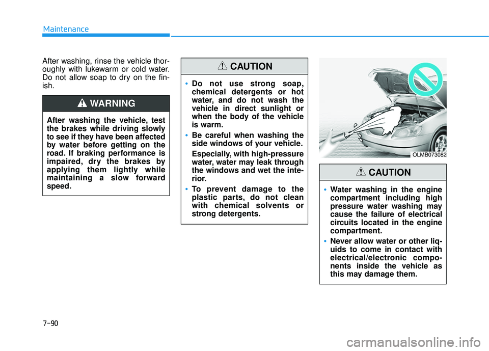
Water washing in the engine
compartment including high
pressure water washing may
cause the failure of electrical
circuits located in the engine
compartment.
Never allow water or other liq-
uids to come in contact with
electrical/electronic compo-
nents inside the vehicle as
this may damage them.
CAUTION
Do not use strong soap,
chemical detergents or hot
water, and do not wash the
vehicle in direct sunlight or
when the body of the vehicle
is warm.
Be careful when washing the
side windows of your vehicle.
Especially, with high-pressure
water, water may leak through
the windows and wet the inte-
rior.
To prevent damage to the
plastic parts, do not clean
with chemical solvents or
strong detergents.
CAUTION
After washing the vehicle, test
the brakes while driving slowly
to see if they have been affected
by water before getting on the
road. If braking performance is
impaired, dry the brakes by
applying them lightly while
maintaining a slow forward
speed.
WARNING
Page 557 of 586

7-97
7
Maintenance
Canister
Fuel vapors generated inside the fuel
tank are absorbed and stored in the
onboard canister. When the engine is
running, the fuel vapors absorbed in
the canister are drawn into the surge
tank through the purge control sole-
noid valve.
Purge Control Solenoid Valve(PCSV)
The purge control solenoid valve is
controlled by the Engine Control
Module (ECM); when the engine
coolant temperature is low during
idling, the PCSV closes so that evap-
orated fuel is not taken into the
engine. After the engine warms-up
during ordinary driving, the PCSV
opens to introduce evaporated fuel to
the engine.
3. Exhaust Emission Control System
The Exhaust Emission Control
System is a highly effective system
which controls exhaust emissions
while maintaining good vehicle per-
formance.
When the engine starts or fails to
start, excessive attempts to restart
the engine may cause damage to the
emission system.
Engine exhaust (carbon monox-
ide) precautions
Carbon monoxide can be present
with other exhaust fumes. If you
smell exhaust fumes of any kind in
your vehicle, drive with all the win-
dows fully open. Have your vehicle
checked and repaired immediately.
Engine exhaust gases contain
carbon monoxide (CO). Though
colorless and odorless, it is
dangerous and could be lethal if
inhaled. Follow the instructions
on this page to avoid CO poi-
soning.
WARNING