2017 FORD SUPER DUTY warning
[x] Cancel search: warningPage 262 of 636
Note:
It is recommended that you turn the
collision warning system off if a snow plow
or similar object is installed in such a way
that it may block the radar sensor. Your
vehicle will remember the selected setting
across key cycles.
Note: When possible, the manufacturer
recommends using the highest sensitivity
setting. If warnings are too frequent, you can
reduce your system's sensitivity. Reduced
sensitivity causes fewer and later system
warnings. See General Information (page
111). Blocked Sensors If a blocked sensor message appears in the
information display, dirt, water, or an object
is blocking the sensor. The sensor is
located behind a cover near the driver side
of the lower grille. If anything blocks the
sensor, your vehicle cannot see through
the sensor, and the collision warning
system will not work. Possible causes for
the blocked sensor message and corrective
actions are listed below.
Action
Cause
Clean the radar sensor cover or remove theobstruction
The radar sensor cover in the grille is dirty
or obstructed
Wait a short time. The radar may take
several minutes to reset after you remove the obstruction
The surface of the radar sensor cover is
clean but the message remains in the display
The collision warning system is temporarilydisabled. Shortly after weather conditions improve, the collision warning system automatically reactivates
Heavy rain, spray, snow or fog in the air
interferes with the radar signals
The collision warning system is temporarilydisabled. Shortly after weather conditions improve, the collision warning system automatically reactivates
Swirling water, snow or ice on the road
surface interferes with the radar signals
259
Super Duty (TFE) Canada/United States of America, enUSA, First Printing Driving AidsE183741
Page 263 of 636
System Limitations
WARNING
The collision warning system
’s brake
support only reduces collision speed
if you first apply your brakes. You
must brake as you would in any typical
braking situation. Due to the nature of radar technology,
there may be certain instances where
vehicles do not provide a collision warning.
These include:
•
Stationary vehicles or vehicles moving
below 6 mph (10 km/h).
• Pedestrians or objects in the roadway.
• Oncoming vehicles in the same lane.
• Severe weather conditions (see
blocked sensor section).
• Debris build-up on the grille near the
headlamps (see blocked sensor
section).
• Small distance to vehicle ahead.
• Large steering wheel and pedal
movements (very active driving style).
Damage to the front end of your vehicle
may alter the radar sensor's coverage area.
This may result in missed or false collision
warnings. Have an authorized dealer check
your radar sensor for proper coverage and
operation.
260
Super Duty (TFE) Canada/United States of America, enUSA, First Printing Driving Aids
Page 265 of 636
Payload is the combined weight
of cargo and passengers that your
vehicle is carrying. The maximum
payload for your vehicle appears
on the Tire and Loading label. The
label is either on the B-pillar or the
edge of the driver door. Vehicles
exported outside the US and
Canada may not have a tire and
loading label. Look for
“The
combined weight of occupants
and cargo should never exceed
XXX kg OR XXX lb ” for maximum
payload. The payload listed on the
Tire and Loading Information label
is the maximum payload for your
vehicle as built by the assembly
plant. If you install any additional
equipment on your vehicle, you
must determine the new payload.
Subtract the weight of the
equipment from the payload listed
on the Tire and Loading label.
When towing, trailer tongue
weight or king pin weight is also
part of payload. WARNING
The appropriate loading
capacity of your vehicle can
be limited either by volume
capacity (how much space is
available) or by payload capacity
(how much weight the vehicle
should carry). Once you have
reached the maximum payload of
your vehicle, do not add more
cargo, even if there is space
available. Overloading or
improperly loading your vehicle
can contribute to loss of vehicle
control and vehicle rollover. GAWR (Gross Axle Weight
Rating)
GAWR is the maximum allowable
weight that a single axle (front or
rear) can carry. These numbers
are on the Safety Compliance
Certification label. The label is
located on the door hinge pillar,
door-latch post, or the door edge
that meets the door-latch post,
next to the driver seating position.
The total load on each axle must
never exceed its Gross Axle
Weight Rating.
GVWR (Gross Vehicle Weight
Rating)
GVWR is the maximum allowable
weight of the fully loaded vehicle.
This includes all options,
equipment, passengers and cargo.
It appears on the Safety
Compliance Certification label.
The label is located on the door
hinge pillar, door-latch post, or the
door edge that meets the
door-latch post, next to the driver
seating position.
The gross vehicle weight must
never exceed the Gross Vehicle
Weight Rating.
262
Super Duty (TFE) Canada/United States of America, enUSA, First Printing Load Carrying
Page 266 of 636
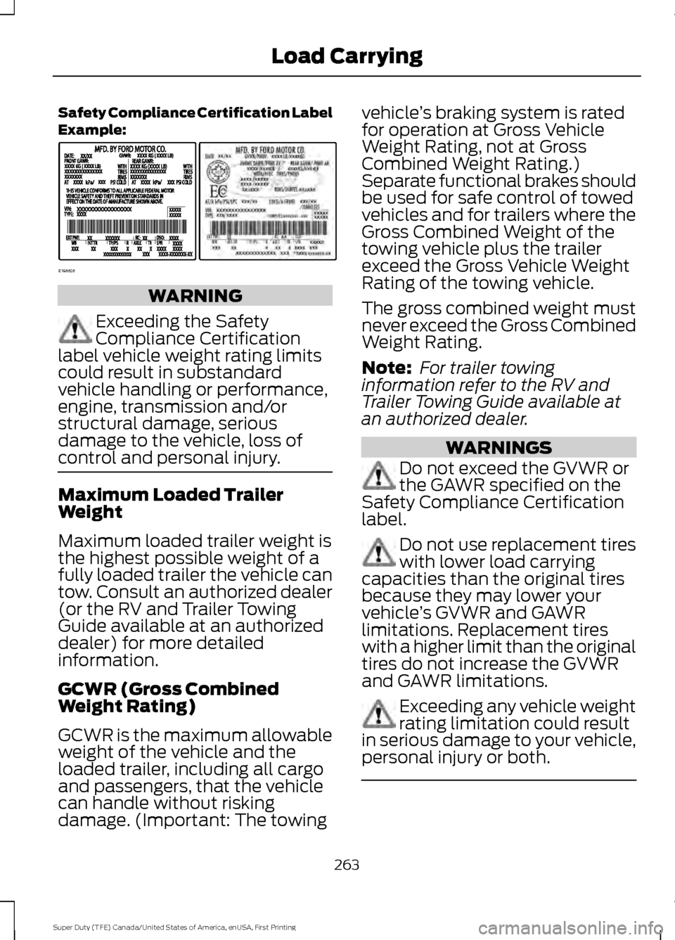
Safety Compliance Certification Label
Example:
WARNING
Exceeding the Safety
Compliance Certification
label vehicle weight rating limits
could result in substandard
vehicle handling or performance,
engine, transmission and/or
structural damage, serious
damage to the vehicle, loss of
control and personal injury. Maximum Loaded Trailer
Weight
Maximum loaded trailer weight is
the highest possible weight of a
fully loaded trailer the vehicle can
tow. Consult an authorized dealer
(or the RV and Trailer Towing
Guide available at an authorized
dealer) for more detailed
information.
GCWR (Gross Combined
Weight Rating)
GCWR is the maximum allowable
weight of the vehicle and the
loaded trailer, including all cargo
and passengers, that the vehicle
can handle without risking
damage. (Important: The towing vehicle
’s braking system is rated
for operation at Gross Vehicle
Weight Rating, not at Gross
Combined Weight Rating.)
Separate functional brakes should
be used for safe control of towed
vehicles and for trailers where the
Gross Combined Weight of the
towing vehicle plus the trailer
exceed the Gross Vehicle Weight
Rating of the towing vehicle.
The gross combined weight must
never exceed the Gross Combined
Weight Rating.
Note: For trailer towing
information refer to the RV and
Trailer Towing Guide available at
an authorized dealer. WARNINGS
Do not exceed the GVWR or
the GAWR specified on the
Safety Compliance Certification
label. Do not use replacement tires
with lower load carrying
capacities than the original tires
because they may lower your
vehicle ’s GVWR and GAWR
limitations. Replacement tires
with a higher limit than the original
tires do not increase the GVWR
and GAWR limitations. Exceeding any vehicle weight
rating limitation could result
in serious damage to your vehicle,
personal injury or both. 263
Super Duty (TFE) Canada/United States of America, enUSA, First Printing Load CarryingE198828
Page 268 of 636
- 1200 = - 240 pounds. No, you do
not have enough cargo capacity
to carry that much weight. In
metric units, the calculation would
be: 635 kilograms - (2 x 99
kilograms) - (12 x 45 kilograms) =
635 - 198 - 540 = -103 kilograms.
You will need to reduce the load
weight by at least 240 pounds
(104 kilograms). If you remove
three 100-pound (45-kilogram)
cement bags, then the load
calculation would be:1400 - (2 x
220) - (9 x 100) = 1400 - 440 -
900 = 60 pounds. Now you have
the load capacity to transport the
cement and your friend home. In
metric units, the calculation would
be: 635 kilograms - (2 x 99
kilograms) - (9 x 45 kilograms) =
635 - 198 - 405 = 32 kilograms.
The above calculations also
assume that the loads are
positioned in your vehicle in a
manner that does not overload
the front or the rear gross axle
weight rating specified for your
vehicle on the Safety Compliance
Certification label.
Special Loading Instructions
for Owners of Pick-up Trucks
and Utility-type Vehicles
WARNING
Loaded vehicles may handle
differently than unloaded
vehicles. Take extra precautions,
such as slower speeds and
increased stopping distance, when
driving a heavily loaded vehicle. BED RAMPS (If Equipped)
WARNINGS
The slide action of the ramp is a
pinch point. Do not place fingers or
hands in the pinch point.
Extend and retract the ramp only
when connected to the tailgate
plate.
Be sure the ramp is installed
correctly when loading and
unloading equipment on and off the
ramp. Do not step or sit on the ramp when
it is in the stowed position.
Install the ramp only within the
prescribed ramp angles.
Note:
The ramp maximum capacity is
800 lb (363 kg)
.
Note: Verify the ramp is on stable ground
before usage.
Note: For loading and unloading
equipment, your ramp should be set
between
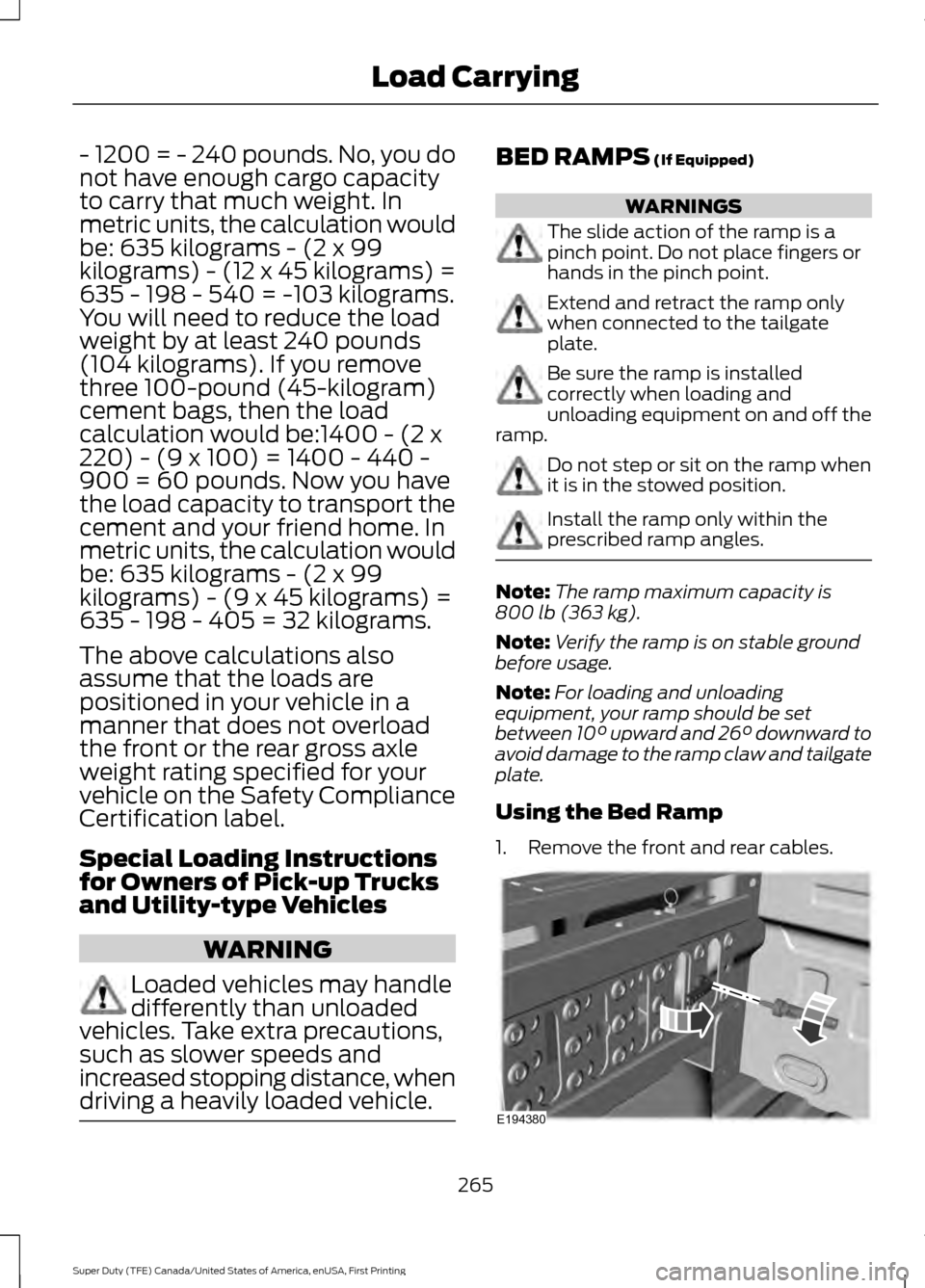
10° upward and 26° downward to
avoid damage to the ramp claw and tailgate
plate.
Using the Bed Ramp
1. Remove the front and rear cables. 265
Super Duty (TFE) Canada/United States of America, enUSA, First Printing Load CarryingE194380
Page 271 of 636
TOWING A TRAILER
WARNINGS
Towing trailers beyond the
maximum recommended
gross trailer weight exceeds the
limit of your vehicle and could
result in engine damage,
transmission damage, structural
damage, loss of vehicle control,
vehicle rollover and personal
injury. Do not exceed the GVWR or
the GAWR specified on the
certification label. Note:
See Recommended
Towing Weights (page 277).
Your vehicle may have electrical
items, such as fuses or relays,
related to towing. See
Fuses
(page 310).
Your vehicle's load capacity
designation is by weight, not by
volume, so you cannot necessarily
use all available space when
loading a vehicle or trailer.
Towing a trailer places an extra
load on your vehicle's engine,
transmission, axle, brakes, tires
and suspension. Inspect these
components periodically during,
and after, any towing operation. Load Placement
To help minimize how trailer
movement affects your vehicle
when driving:
•
Load the heaviest items closest
to the trailer floor.
• Load the heaviest items
centered between the left and
right side trailer tires.
• Load the heaviest items above
the trailer axles or just slightly
forward toward the trailer
tongue. Do not allow the final
trailer tongue weight to go
above or below 10-15% of the
loaded trailer weight.
• Select a ball mount with the
correct rise or drop and load
capacity. When both the
loaded vehicle and trailer are
connected, the trailer frame
should be level, or slightly
angled down toward your
vehicle, when viewed from the
side.
When driving with a trailer or
payload, a slight takeoff vibration
or shudder may be present due to
the increased payload weight.
Additional information regarding
proper trailer loading and setting
your vehicle up for towing is
located in another chapter of this
manual. See
Load Limit (page
261).
You can also find information in
the
RV & Trailer Towing Guide
available at your authorized
dealer, or online.
268
Super Duty (TFE) Canada/United States of America, enUSA, First Printing Towing
Page 272 of 636
RV & Trailer Towing Guide Online
http://www.fleet.ford.com/towing-guides/
Website
TRAILER REVERSING AIDS
Trailer Reverse Guidance WARNING
Driving while distracted can result in
loss of vehicle control, crash and
injury. We strongly recommend that
you use extreme caution when using any
device that may take your focus off the
road. Your primary responsibility is the safe
operation of your vehicle. We recommend
against the use of any hand-held device
while driving and encourage the use of
voice-operated systems when possible.
Make sure you are aware of all applicable
local laws that may affect the use of
electronic devices while driving. Note:
The system is not a substitute for
safe driving practices.
Note: You must always be aware of the
vehicle and trailer combination and the
surrounding environment.
Note: The system does not detect or
prevent the vehicle or trailer from making
contact with obstacles in the surrounding
environment.
Note: Keep in mind that the front end of
the vehicle swings out when changing the
direction of the trailer. Note:
The system relies on user
measurements to determine sticker
placement and system limits. It is critical to
take the key measurements correctly.
Incorrect measurements can result in the
improper function of the system up to and
including contact between the vehicle and
trailer.
Note: The system limits vehicle speed when
backing up. The system is not a replacement
for proper use of the throttle and brake
pedals.
Principle of Operation
Trailer Reverse Guidance (TRG) is a driver
assistance feature that helps take the
guesswork out of getting your trailer
positioned where you want it, quickly and
easily, while you're driving in reverse.
Each trailer you use with your vehicle has
to be setup once.
Sticker placement is extremely important
and there are specific placement rules.
Setting Up Trailer Reverse
Guidance
Note: Once you have entered a trailer's
information into the system, it is stored for
easy recall. A maximum of 10 trailers can be
added to the system.
Step 1: Position your Vehicle and Trailer
Hitch your trailer to the truck and connect
the electrical wiring harness. Check to
make sure that the wiring is working See
Essential Towing Checks (page 281).
Park your vehicle and hitched trailer on a
level surface.
269
Super Duty (TFE) Canada/United States of America, enUSA, First Printing Towing
Page 277 of 636
Accurate measurements are critical to
correct system function. If you need to
check measurements entered or change
them you can access them through the
trailer menus in the information display.
Choose the option to change the sticker
from the change trailer settings menu. It is
not necessary to remove the sticker if you
are just reviewing or changing
measurements.
The following menu warnings or difficulties
may occur during setup. Tips to resolve
them are listed below.
Measurement A has reached maximum or
minimum value:
•
The system is designed to work with
drawbars that have a license plate to
hitch ball center measurement of 9 in
(229 mm) to 16 in (406 mm) when
installed. Do not attempt to use
drawbars that have a length outside
this range as the system performance
will be degraded and could cause
improper system function.
• Make sure that the measurement being
made is the horizontal distance only
from license plate and the hitch ball
center. A straight line distance that
includes any vertical rise or drop will
increase the measurement and make
it inaccurate. Inaccurate
measurements will degrade system
performance and could cause improper
system function. See step 4 of the
setup instruction to review
measurement instructions. Measurement B has reached maximum or
minimum value:
•
Make sure that the sticker placement
instruction in step 3 of the setup has
been followed. Stickers placed outside
the allowed zone will adversely affect
the system performance and could
cause improper feature function.
• Make sure that the measurement being
made is the horizontal distance only
from center of sticker to the hitch ball
center. A straight line distance that
includes any vertical rise or drop will
increase the measurement and cause
an inaccurate value to be entered into
the system. See step 4 of the setup for
additional measurement instructions.
Measurement C has reached maximum or
minimum value:
• Make sure that the sticker placement
instructions in step 3 of the setup have
been followed. Stickers placed outside
the allowed zone will adversely affect
the system performance and could
cause improper feature function. If you
have met all the criteria for sticker
placement and you see this message
this sticker is either too far below or too
close to the camera to properly
recognize the sticker. In order for the
system to operate correctly the sticker
height must be lowered if you receive
the minimum warning or the sticker
height must be raised if you receive the
maximum warning.
•Only one sticker can be placed on
the trailer for correct system
function. The previous sticker must
be removed or covered so only one
sticker is visible to the camera.
• Measurement B and C must be
measured again if a new sticker is
placed on the trailer.
274
Super Duty (TFE) Canada/United States of America, enUSA, First Printing Towing