2017 FORD SUPER DUTY ignition
[x] Cancel search: ignitionPage 361 of 636
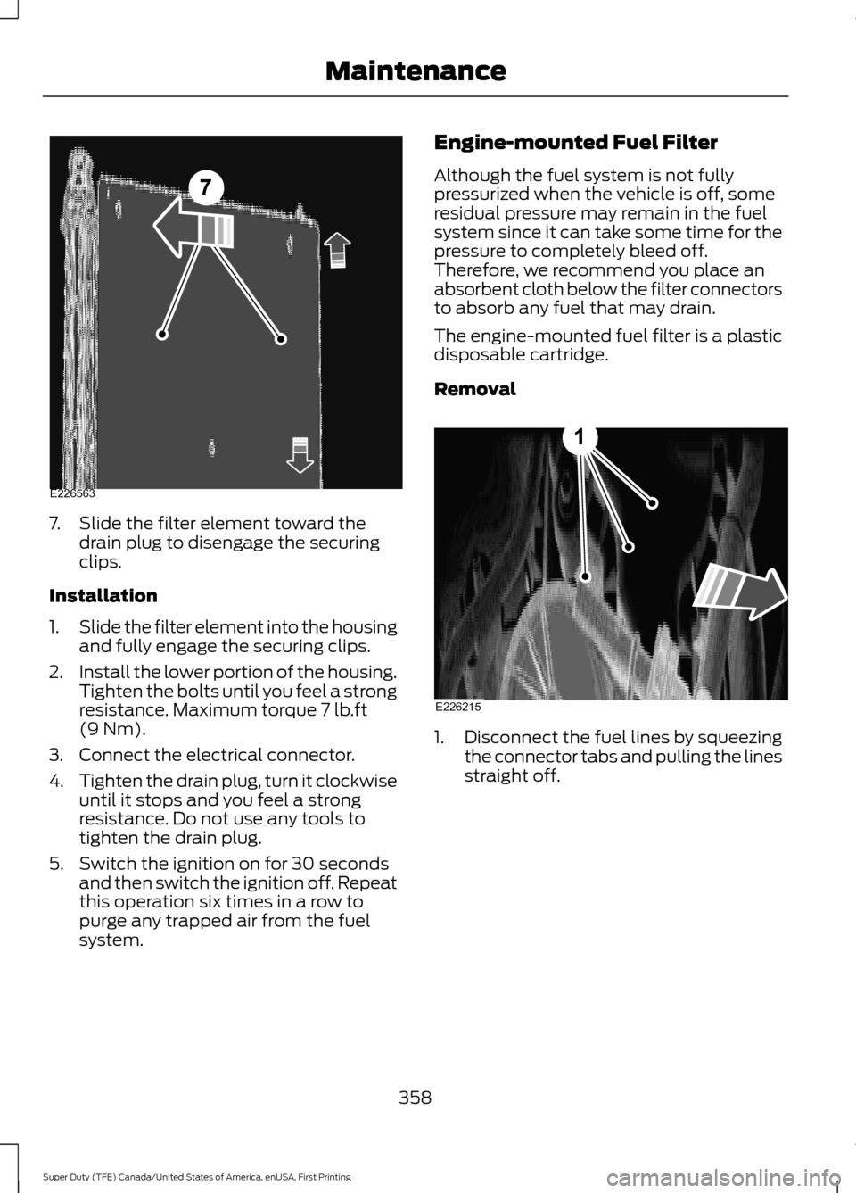
7. Slide the filter element toward the
drain plug to disengage the securing
clips.
Installation
1. Slide the filter element into the housing
and fully engage the securing clips.
2. Install the lower portion of the housing.
Tighten the bolts until you feel a strong
resistance. Maximum torque 7 lb.ft
(9 Nm).
3. Connect the electrical connector.
4. Tighten the drain plug, turn it clockwise
until it stops and you feel a strong
resistance. Do not use any tools to
tighten the drain plug.
5. Switch the ignition on for 30 seconds and then switch the ignition off. Repeat
this operation six times in a row to
purge any trapped air from the fuel
system. Engine-mounted Fuel Filter
Although the fuel system is not fully
pressurized when the vehicle is off, some
residual pressure may remain in the fuel
system since it can take some time for the
pressure to completely bleed off.
Therefore, we recommend you place an
absorbent cloth below the filter connectors
to absorb any fuel that may drain.
The engine-mounted fuel filter is a plastic
disposable cartridge.
Removal
1.
Disconnect the fuel lines by squeezing
the connector tabs and pulling the lines
straight off.
358
Super Duty (TFE) Canada/United States of America, enUSA, First Printing Maintenance7
E226563 E226215
1
Page 362 of 636
2.
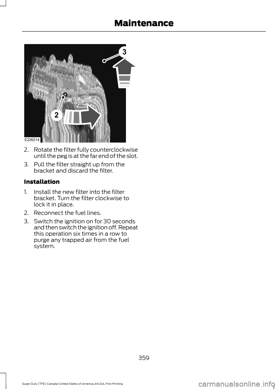
Rotate the filter fully counterclockwise
until the peg is at the far end of the slot.
3. Pull the filter straight up from the bracket and discard the filter.
Installation
1. Install the new filter into the filter bracket. Turn the filter clockwise to
lock it in place.
2. Reconnect the fuel lines.
3. Switch the ignition on for 30 seconds and then switch the ignition off. Repeat
this operation six times in a row to
purge any trapped air from the fuel
system.
359
Super Duty (TFE) Canada/United States of America, enUSA, First Printing MaintenanceE226214
2
3
Page 366 of 636
•
Never wash or rinse any ignition coil,
spark plug wire or spark plug well, or
the area in and around these locations.
• Cover the battery, power distribution
box, and air filter assembly to prevent
water damage when cleaning the
engine.
CLEANING THE EXHAUST -
6.7L DIESEL WARNINGS
Failure to maintain the functional
holes, in the tailpipe section of the
exhaust, clean and free of debris or
foreign material may result in the holes
becoming blocked or plugged. Do not
modify or remove the tail-pipe section.
Blocked or plugged holes or
removal/modification of the system could
result in elevated exhaust gas
temperatures which may result in
vehicle/property damage or personal
injury. The normal operating temperature
of the exhaust system is very high.
Never work around or attempt to
repair any part of the exhaust system until
it has cooled. Use special care when
working around the diesel oxidation
catalytic converter and/or the diesel
particulate filter (DPF). The diesel
oxidation catalytic converter and/or the
DPF heats up to a high temperature after
only a short period of engine operation and
can stay hot even after the engine is turned
off. Failure to follow these instructions may
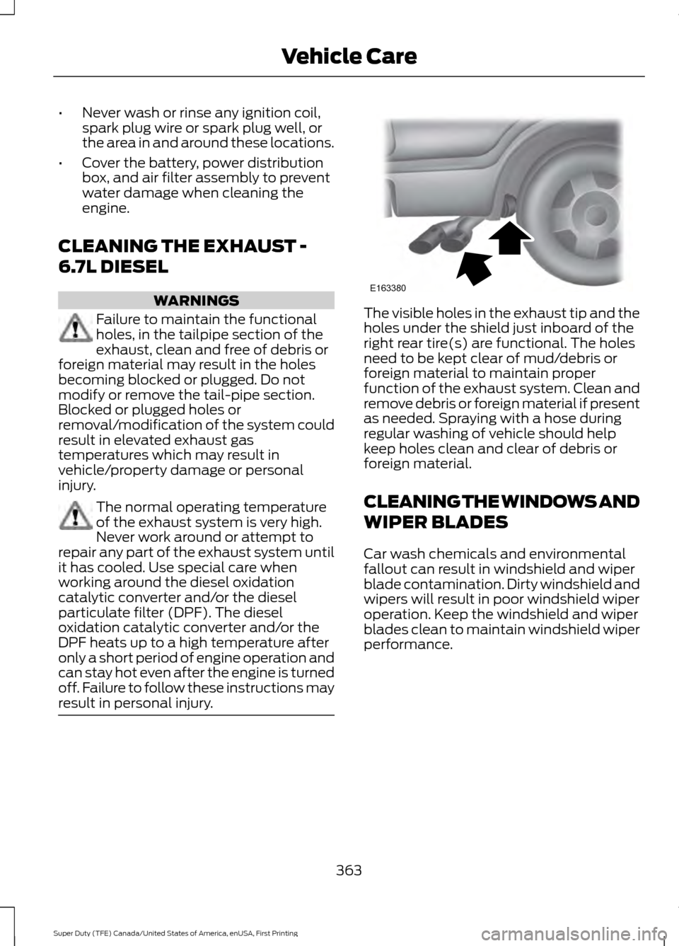
result in personal injury. The visible holes in the exhaust tip and the
holes under the shield just inboard of the
right rear tire(s) are functional. The holes
need to be kept clear of mud/debris or
foreign material to maintain proper
function of the exhaust system. Clean and
remove debris or foreign material if present
as needed. Spraying with a hose during
regular washing of vehicle should help
keep holes clean and clear of debris or
foreign material.
CLEANING THE WINDOWS AND
WIPER BLADES
Car wash chemicals and environmental
fallout can result in windshield and wiper
blade contamination. Dirty windshield and
wipers will result in poor windshield wiper
operation. Keep the windshield and wiper
blades clean to maintain windshield wiper
performance.
363
Super Duty (TFE) Canada/United States of America, enUSA, First Printing Vehicle CareE163380
Page 398 of 636
•
To reduce the chances of interference
from another vehicle, perform the
system reset procedure at least three
feet (one meter) away from another
Ford Motor Company vehicle
undergoing the system reset procedure
at the same time.
• Do not wait more than two minutes
between resetting each tire sensor or
the system will time-out and the entire
procedure will have to be repeated on
all four wheels.
• A double horn will sound indicating the
need to repeat the procedure.
Performing the System Reset Procedure
(Single Rear Wheel)
Read the entire procedure before
attempting.
1. Drive the vehicle above 20 mph
(32 km/h) for at least two minutes,
then park in a safe location where you
can easily get to all four tires and have
access to an air pump.
2. Place the ignition in the off position and
keep the key in the ignition.
3. Cycle the ignition to the on position with the engine off.
4. Turn the hazard flashers on then off three times. You must accomplish this
within 10 seconds. If the reset mode
has been entered successfully, the horn
will sound once, the system indicator
will flash and a message is shown in
the information display. If this does not
occur, please try again starting at Step
2. If after repeated attempts to enter
the reset mode, the horn does not
sound, the system indicator does not
flash and no message is shown in the
information display, seek service from
your authorized dealer. 5. Train the tire pressure monitoring
system sensors in the tires using the
following system reset sequence
starting with the left front tire in the
following clockwise order: Left front
(driver's side front tire), Right front
(passenger's side front tire), Right rear
(passenger's side rear tire), Left rear
(driver's side rear tire).
6. Remove the valve cap from the valve stem on the left front tire. Decrease the
air pressure until the horn sounds.
Note: The single horn chirp confirms that
the sensor identification code has been
learned by the module for this position. If a
double horn is heard, the reset procedure
was unsuccessful, and you must repeat it.
7. Remove the valve cap from the valve stem on the right front tire. Decrease
the air pressure until the horn sounds.
8. Remove the valve cap from the valve stem on the right rear tire. Decrease the
air pressure until the horn sounds.
9. Remove the valve cap from the valve stem on the left rear tire. Decrease the
air pressure until the horn sounds.
Training is complete after the horn
sounds for the last tire trained (driver's
side rear tire), the system indicator
stops flashing, and a message is shown
in the information display.
10. Turn the ignition off. If two short horn
beeps are heard, the reset procedure
was unsuccessful and you must
repeat it. If after repeating the
procedure and two short beeps are
heard when the ignition is turned to
off, seek assistance from your
authorized dealer.
395
Super Duty (TFE) Canada/United States of America, enUSA, First Printing Wheels and Tires
Page 399 of 636
11.
Set all four tires to the recommended
air pressure as indicated on the
Safety Compliance Certification
Label (affixed to either the door hinge
pillar, door-latch post, or the door
edge that meets the door-latch post,
next to the driver's seating position)
or Tire Label located on the B-Pillar
or the edge of the driver's door.
Performing the System Reset Procedure
(Dual Rear Wheel)
For further information see
Understanding Your Tire Pressure
Monitoring System and refer to Dual
Rear Wheel, earlier in this section.
Read the entire procedure before
attempting.
1. Drive the vehicle above
20 mph
(32 km/h) for at least two minutes,
then park in a safe location where you
can easily get to all four tires and have
access to an air pump.
2. Place the ignition in the off position and
keep the key in the ignition.
3. Cycle the ignition to the on position with the engine off.
4. Turn the hazard flashers on then off three times. You must accomplish this
within 10 seconds. If the reset mode
has been entered successfully, the horn
will sound once, the system indicator
will flash and a message is shown in
the information display. If this does not
occur, please try again starting at Step
2. If after repeated attempts to enter
the reset mode, the horn does not
sound, the system indicator does not
flash and no message is shown in the
information display, seek service from
your authorized dealer. 5. Train the tire pressure monitoring
system sensors in the tires using the
following system reset sequence
starting with the left front tire in the
following order: Left front (driver's side
front tire), Right front (passenger's side
front tire), Right outer rear (passenger's
side rear outer tire), Right inner rear
(passenger's side rear inner tire), Left
outer rear (driver's side rear outer tire),
Left inner rear (driver's side rear inner
tire).
6. Remove the valve cap from the valve stem on the left front tire. Decrease the
air pressure until the horn sounds.
Note: The single horn chirp confirms that
the sensor identification code has been
learned by the module for this position. If a
double horn is heard, the reset procedure
was unsuccessful, and you must repeat it.
7. Remove the valve cap from the valve stem on the right front tire. Decrease
the air pressure until the horn sounds.
8. Remove the valve cap from the valve stem on the right outer rear tire.
Decrease the air pressure until the horn
sounds.
9. Remove the valve cap from the valve stem on the right inner rear tire.
Decrease the air pressure until the horn
sounds.
10. Remove the valve cap from the valve
stem on the left outer rear tire.
Decrease the air pressure until the
horn sounds.
11. Remove the valve cap from the valve
stem on the left inner rear tire.
Decrease the air pressure until the
horn sounds. Training is complete
after the horn sounds for the last tire
trained, the system indicator stops
flashing, and a message is shown in
the information display.
396
Super Duty (TFE) Canada/United States of America, enUSA, First Printing Wheels and Tires
Page 400 of 636
12.
Turn the ignition off. If two short horn
beeps are heard, the reset procedure
was unsuccessful and you must
repeat it. If after repeating the
procedure and two short beeps are
heard when the ignition is turned to
off, seek assistance from your
authorized dealer.
13. Set all four tires to the recommended
air pressure as indicated on the
Safety Compliance Certification
Label (affixed to either the door hinge
pillar, door-latch post, or the door
edge that meets the door-latch post,
next to the driver's seating position)
or Tire Label located on the B-Pillar
or the edge of the driver's door.
Trailer Tire Pressure Monitoring
System (If Equipped)
Note: Additional equipment may be
required for your vehicle to support trailer
tire pressure monitoring. See your authorized
dealer for more information.
Note: The trailer tire pressure monitoring
system is not a substitute for proper tire
maintenance. It is your responsibility to
maintain correct tire pressures at all times.
Note: If a trailer tire is repaired, replaced or
broken down for service, the screw and valve
on the trailer tire pressure sensor should be
replaced. See your authorized dealer for
details. The trailer tire pressure monitoring system
is an added safety feature that allows you
to view your trailer tire pressures through
the information display. See
General
Information (page 111). Tire pressure
sensors are mounted into each tire on your
trailer. The sensors send a message to your
vehicle indicating the current trailer tire
pressure.
If the trailer tire pressure monitoring
system detects that a tire is low, a warning
message appears in the information
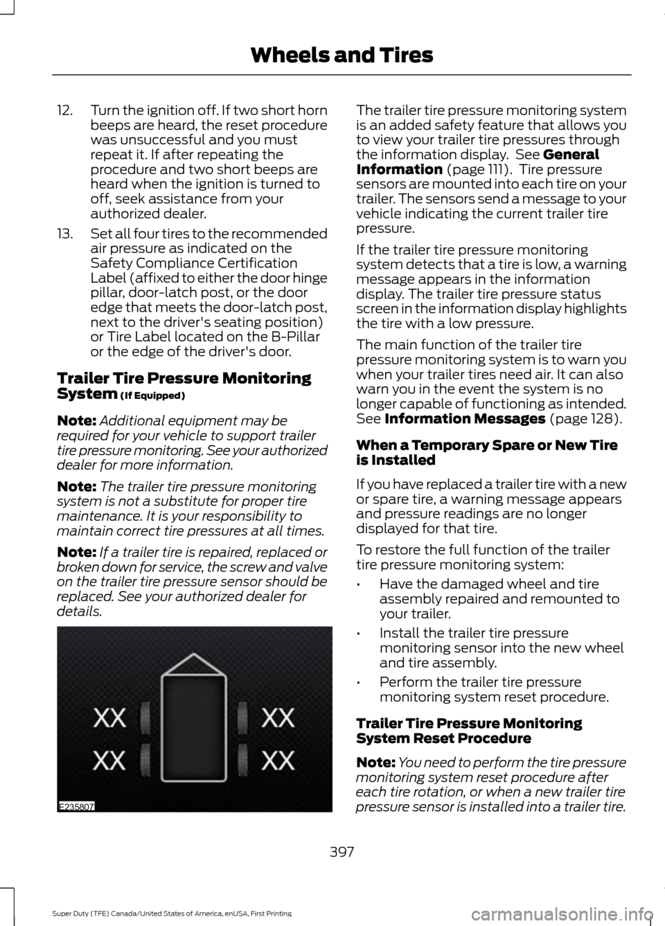
display. The trailer tire pressure status
screen in the information display highlights
the tire with a low pressure.
The main function of the trailer tire
pressure monitoring system is to warn you
when your trailer tires need air. It can also
warn you in the event the system is no
longer capable of functioning as intended.
See
Information Messages (page 128).
When a Temporary Spare or New Tire
is Installed
If you have replaced a trailer tire with a new
or spare tire, a warning message appears
and pressure readings are no longer
displayed for that tire.
To restore the full function of the trailer
tire pressure monitoring system:
• Have the damaged wheel and tire
assembly repaired and remounted to
your trailer.
• Install the trailer tire pressure
monitoring sensor into the new wheel
and tire assembly.
• Perform the trailer tire pressure
monitoring system reset procedure.
Trailer Tire Pressure Monitoring
System Reset Procedure
Note: You need to perform the tire pressure
monitoring system reset procedure after
each tire rotation, or when a new trailer tire
pressure sensor is installed into a trailer tire.
397
Super Duty (TFE) Canada/United States of America, enUSA, First Printing Wheels and TiresE235807
Page 414 of 636
ENGINE SPECIFICATIONS - 6.2L
6.2L V8 Engine
Engine
378
Cubic inches
Minimum 87 octane
Required fuel
1-5-4-8-6-3-7-2
Firing order
Coil on plug
Ignition system
0.041-0.047 in (1.04-1.20 mm)
Spark plug gap
9.8:1
Compression ratio
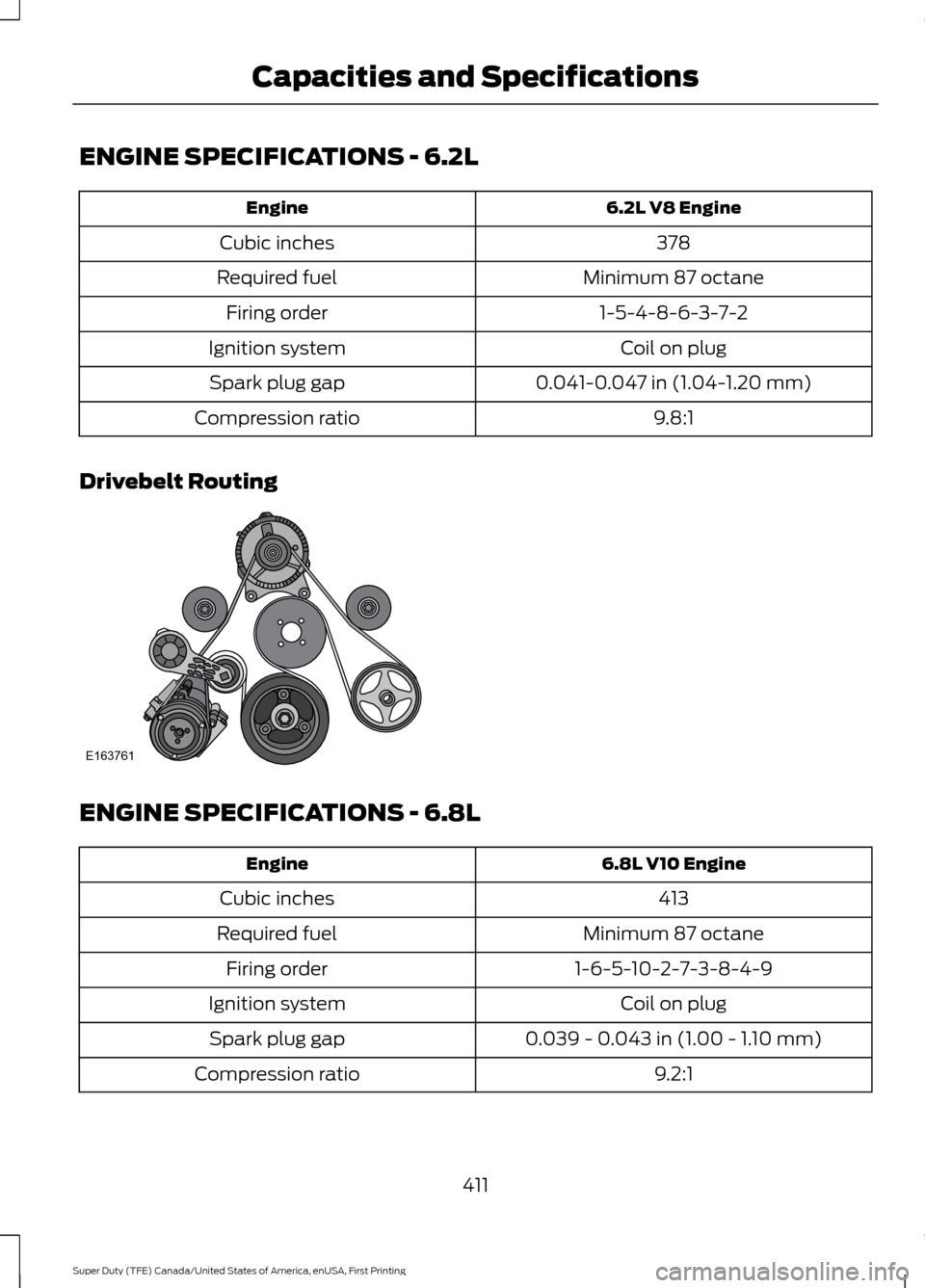
Drivebelt Routing ENGINE SPECIFICATIONS - 6.8L
6.8L V10 Engine
Engine
413
Cubic inches
Minimum 87 octane
Required fuel
1-6-5-10-2-7-3-8-4-9
Firing order
Coil on plug
Ignition system
0.039 - 0.043 in (1.00 - 1.10 mm)
Spark plug gap
9.2:1
Compression ratio
411
Super Duty (TFE) Canada/United States of America, enUSA, First Printing Capacities and SpecificationsE163761
Page 457 of 636
Other features, such as text messaging
using Bluetooth and automatic phonebook
download, are phone-dependent features.
To check your phone's compatibility, see
your phone's manual and visit
www.SYNCMyRide.com,
www.SYNCMyRide.ca or
www.syncmaroute.ca.
Pairing a Phone for the First Time
Wirelessly pairing your phone with SYNC
allows you to make and receive hands-free
calls.
Note:
SYNC can support downloading up
to approximately 4000 entries per
Bluetooth-enabled cellular phone.
Note: Make sure to switch on the ignition
and the radio. Shift the transmission into
park (P) for automatic transmission or first
gear for manual transmission.
Using the Audio System
Note: To scroll through the menus, press
the up and down arrows on your audio
system.
1. Make sure to switch on your phone's Bluetooth feature before starting the
search. See your device's manual if
necessary.
2. Press the PHONE button. When the
audio display indicates there is no
paired phone, select the option to add.
3. When a message to begin pairing appears in the audio display, search for
SYNC on your phone to start the pairing
process. 4. When prompted on your cell phone
’s
display, confirm that the PIN provided
by SYNC matches the PIN displayed
on your cell phone. Your phone is now
paired and the display indicates that
the pairing was successful. If you are
prompted to enter a PIN on your device,
enter the PIN displayed on the screen.
The display indicates when the pairing
is successful.
Depending on your phone's capability and
your market, the system may prompt you
with questions, such as setting the current
phone as the primary phone (the phone
SYNC automatically tries to connect with
first upon vehicle start-up) and
downloading your phonebook.
Using Voice Commands Make sure to switch on your
phone's Bluetooth feature
before starting the search. See
your device's manual if necessary.
Press the voice and when prompted
say: Action and Descrip-
tion
Voice Command
Follow the instruc-
tions on the audio
display.
(pair ([Bluetooth]
device | phone |
Bluetooth audio) |
add phone)
You can say any of the voice commands
that appear within open and close brackets
that are separated by |. For example,
where; (what's | what is) appears you say;
what's or what is.
The commands that have [ ] around the
word means that the word is optional.
454
Super Duty (TFE) Canada/United States of America, enUSA, First Printing SYNC™
(If Equipped)E142599