Page 223 of 528
Steps for determining the
correct load limit:
1. Locate the statement "The
combined weight of occupants
and cargo should never exceed
XXX kg or XXX lb." on your
vehicle ’s placard.
2. Determine the combined
weight of the driver and
passengers that will be riding
in your vehicle.
3. Subtract the combined weight
of the driver and passengers
from XXX kg or XXX lb.
4. The resulting figure equals the
available amount of cargo and
luggage load capacity. For
example, if the “XXX” amount
equals 1,400 lb. and there will
be five 150 lb. passengers in
your vehicle, the amount of
available cargo and luggage
load capacity is 650 lb.
(1400-750 (5 x 150) = 650 lb.)
5. Determine the combined
weight of luggage and cargo
being loaded on the vehicle.
That weight may not safely
exceed the available cargo and
luggage load capacity
calculated in Step 4.
6. If your vehicle will be towing a
trailer, load from your trailer
will be transferred to your
vehicle. Consult this manual to
determine how this reduces the
available cargo and luggage
load capacity of your vehicle. Helpful examples for calculating
the available amount of cargo
and luggage load capacity
Suppose your vehicle has a
1400-pound (635-kilogram) cargo
and luggage capacity. You decide
to go golfing. Is there enough load
capacity to carry you, four of your
friends and all the golf bags? You
and four friends average 220
pounds (99 kilograms) each and
the golf bags weigh approximately
30 pounds (13.5 kilograms) each.
The calculation would be: 1400 -
(5 x 220) - (5 x 30) = 1400 - 1100
- 150 = 150 pounds. Yes, you have
enough load capacity in your
vehicle to transport four friends
and your golf bags. In metric units,
the calculation would be: 635
kilograms - (5 x 99 kilograms) -
(5 x 13.5 kilograms) = 635 - 495 -
67.5 = 72.5 kilograms.
Suppose your vehicle has a
1400-pound (635-kilogram) cargo
and luggage capacity. You and
one of your friends decide to pick
up cement from the local home
improvement store to finish that
patio you have been planning for
the past two years. Measuring the
inside of the vehicle with the rear
seat folded down, you have room
for twelve 100-pound
(45-kilogram) bags of cement. Do
you have enough load capacity to
transport the cement to your
home? If you and your friend each
weigh 220 pounds (99 kilograms),
the calculation would be: 1400 -
(2 x 220) - (12 x 100) = 1400 - 440
220
Fusion (CC7) Canada/United States of America, enUSA, First Printing Load Carrying
Page 232 of 528
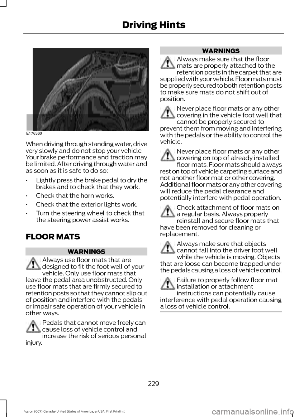
When driving through standing water, drive
very slowly and do not stop your vehicle.
Your brake performance and traction may
be limited. After driving through water and
as soon as it is safe to do so:
•
Lightly press the brake pedal to dry the
brakes and to check that they work.
• Check that the horn works.
• Check that the exterior lights work.
• Turn the steering wheel to check that
the steering power assist works.
FLOOR MATS WARNINGS
Always use floor mats that are
designed to fit the foot well of your
vehicle. Only use floor mats that
leave the pedal area unobstructed. Only
use floor mats that are firmly secured to
retention posts so that they cannot slip out
of position and interfere with the pedals
or impair safe operation of your vehicle in
other ways. Pedals that cannot move freely can
cause loss of vehicle control and
increase the risk of serious personal
injury. WARNINGS
Always make sure that the floor
mats are properly attached to the
retention posts in the carpet that are
supplied with your vehicle. Floor mats must
be properly secured to both retention posts
to make sure mats do not shift out of
position. Never place floor mats or any other
covering in the vehicle foot well that
cannot be properly secured to
prevent them from moving and interfering
with the pedals or the ability to control the
vehicle. Never place floor mats or any other
covering on top of already installed
floor mats. Floor mats should always
rest on top of vehicle carpeting surface and
not another floor mat or other covering.
Additional floor mats or any other covering
will reduce the pedal clearance and
potentially interfere with pedal operation. Check attachment of floor mats on
a regular basis. Always properly
reinstall and secure floor mats that
have been removed for cleaning or
replacement. Always make sure that objects
cannot fall into the driver foot well
while the vehicle is moving. Objects
that are loose can become trapped under
the pedals causing a loss of vehicle control. Failure to properly follow floor mat
installation or attachment
instructions can potentially cause
interference with pedal operation causing
a loss of vehicle control. 229
Fusion (CC7) Canada/United States of America, enUSA, First Printing Driving HintsE176360
Page 240 of 528
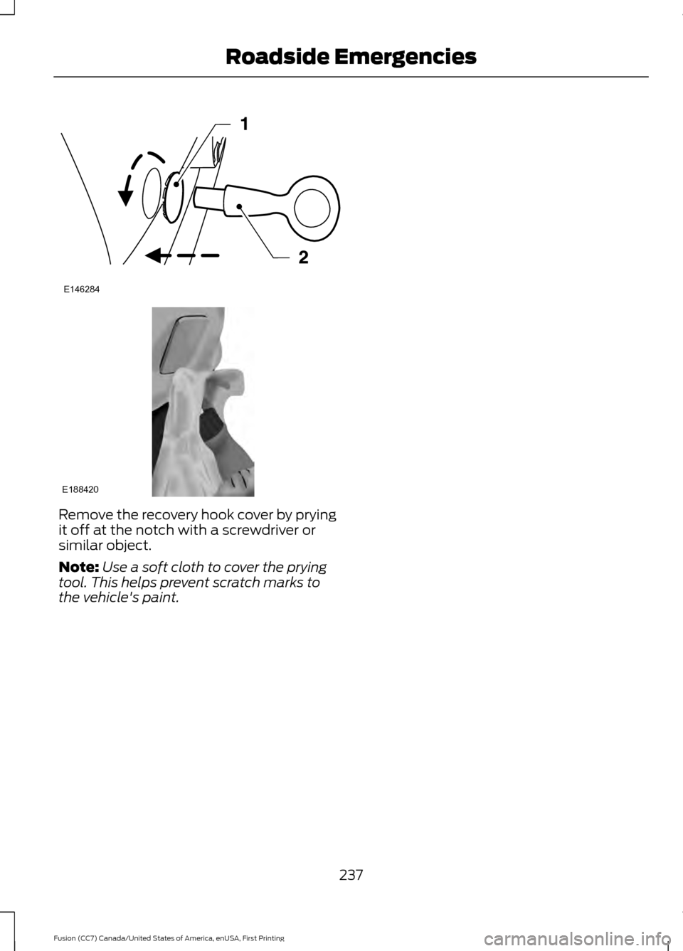
Remove the recovery hook cover by prying
it off at the notch with a screwdriver or
similar object.
Note:
Use a soft cloth to cover the prying
tool. This helps prevent scratch marks to
the vehicle's paint.
237
Fusion (CC7) Canada/United States of America, enUSA, First Printing Roadside EmergenciesE146284 E188420
Page 249 of 528
Protected components
Fuse amp rating
Fuse or relay number
Panoramic moonroof.
30A 3
1
Starter relay.
-
2
Rain sensor.
15A 1
3
Blower motor relay.
—
4
Power point 3 - Back of console.
20A 3
5
Not used.
—
6
Powertrain control module - vehicle power
1.
20A
1
7
Powertrain control module power.
Powertrain control module - vehicle power
2.
20A
1
8
Emission components.
Powertrain control module relay.
—
9
Power point 1 - driver front.
20A 3
10
Powertrain control module - vehicle power
4.
15A
2
11
Ignition coils.
Powertrain control module - vehicle power
3.
15A
2
12
Non-emission components.
Not used.
10A 2
13
Not used.
10A 2
14
Run-start relay.
—
15
Power point 2 - console.
20A 3
16
Not used.
—
17
Not used.
—
18
Run-start electronic power assist steering.
10A 1
19
Adaptive cruise control.
10A 1
20
246
Fusion (CC7) Canada/United States of America, enUSA, First Printing Fuses
Page 253 of 528
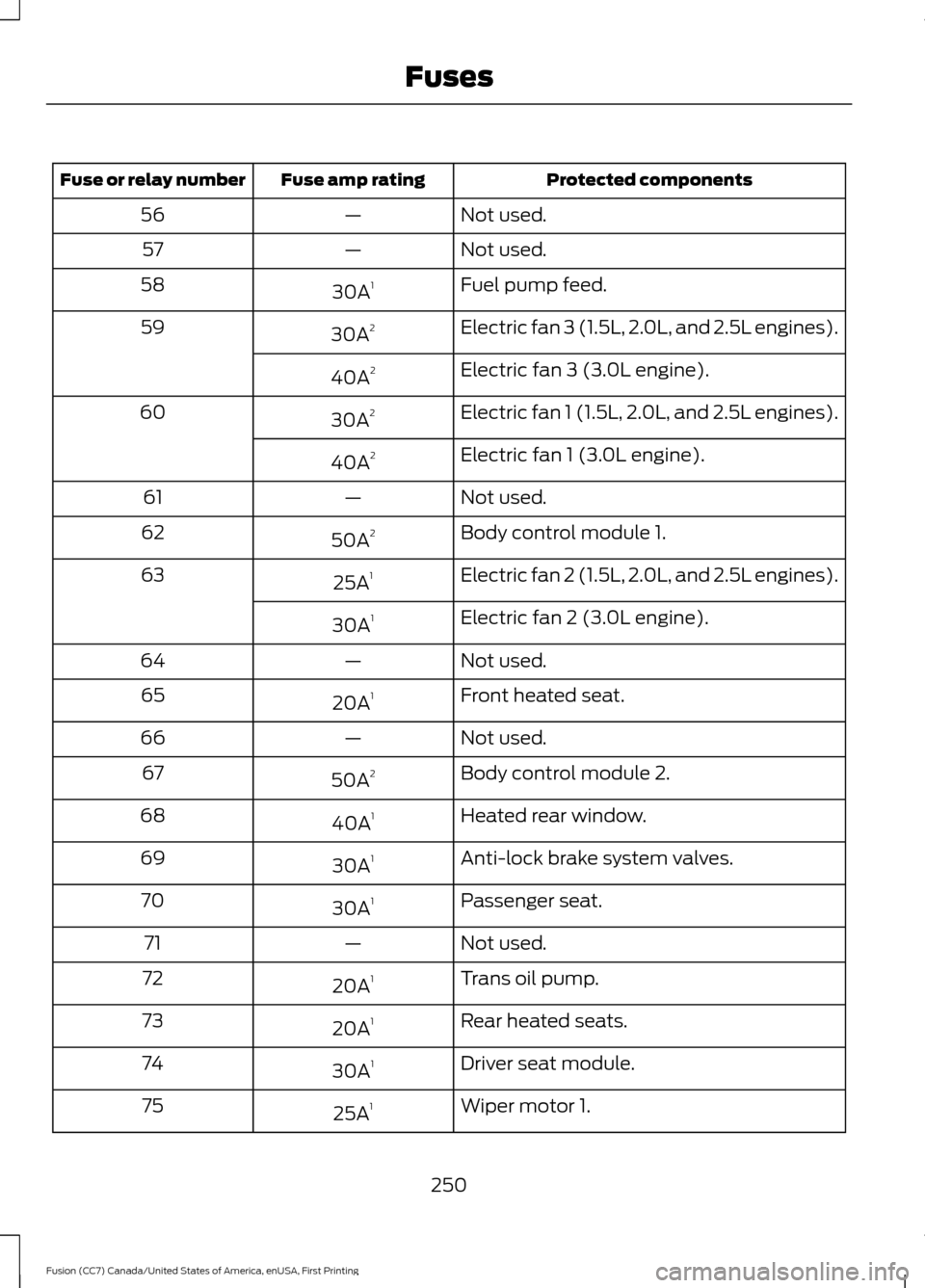
Protected components
Fuse amp rating
Fuse or relay number
Not used.
—
56
Not used.
—
57
Fuel pump feed.
30A 1
58
Electric fan 3 (1.5L, 2.0L, and 2.5L engines).
30A 2
59
Electric fan 3 (3.0L engine).
40A 2
Electric fan 1 (1.5L, 2.0L, and 2.5L engines).
30A 2
60
Electric fan 1 (3.0L engine).
40A 2
Not used.
—
61
Body control module 1.
50A 2
62
Electric fan 2 (1.5L, 2.0L, and 2.5L engines).
25A 1
63
Electric fan 2 (3.0L engine).
30A 1
Not used.
—
64
Front heated seat.
20A 1
65
Not used.
—
66
Body control module 2.
50A 2
67
Heated rear window.
40A 1
68
Anti-lock brake system valves.
30A 1
69
Passenger seat.
30A 1
70
Not used.
—
71
Trans oil pump.
20A 1
72
Rear heated seats.
20A 1
73
Driver seat module.
30A 1
74
Wiper motor 1.
25A 1
75
250
Fusion (CC7) Canada/United States of America, enUSA, First Printing Fuses
Page 255 of 528
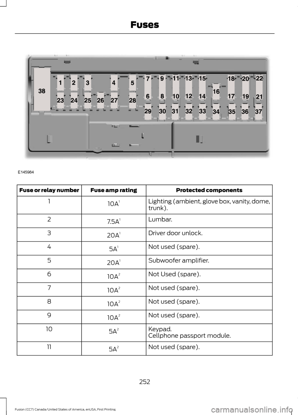
Protected components
Fuse amp rating
Fuse or relay number
Lighting (ambient, glove box, vanity, dome,
trunk).
10A
1
1
Lumbar.
7.5A 1
2
Driver door unlock.
20A 1
3
Not used (spare).
5A 1
4
Subwoofer amplifier.
20A 1
5
Not Used (spare).
10A 2
6
Not used (spare).
10A 2
7
Not used (spare).
10A 2
8
Not used (spare).
10A 2
9
Keypad.
5A 2
10
Cellphone passport module.
Not used (spare).
5A 2
11
252
Fusion (CC7) Canada/United States of America, enUSA, First Printing FusesE145984
Page 256 of 528
Protected components
Fuse amp rating
Fuse or relay number
Climate control.
7.5A 2
12
Gear shift
Steering wheel column lock.
7.5A 2
13
Cluster.
Datalink logic.
Extended power module.
10A 2
14
Datalink gateway module.
10A 2
15
Child lock.
15A 1
16
Decklid-liftglass release.
Not used (spare).
5A 2
17
Push button stop start switch.
5A 2
18
Extended power module.
7.5A 2
19
Adaptive headlamp.
7.5A 2
20
Humidity and in–car temperature sensor.
5A 2
21
Not Used (spare).
5A 2
22
Delayed accessory (power inverter logic,
moonroof logic, driver master switch).
10A
1
23
Central lock unlock.
20A 1
24
Driver door (window, mirror).
30A 1
25
Front passenger door (window, mirror).
30A 1
26
Moonroof.
30A 1
27
Amplifier.
20A 1
28
Rear driver side door (window).
30A 1
29
Rear passenger side door (window).
30A 1
30
Not used (spare).
15A 1
31
253
Fusion (CC7) Canada/United States of America, enUSA, First Printing Fuses
Page 275 of 528
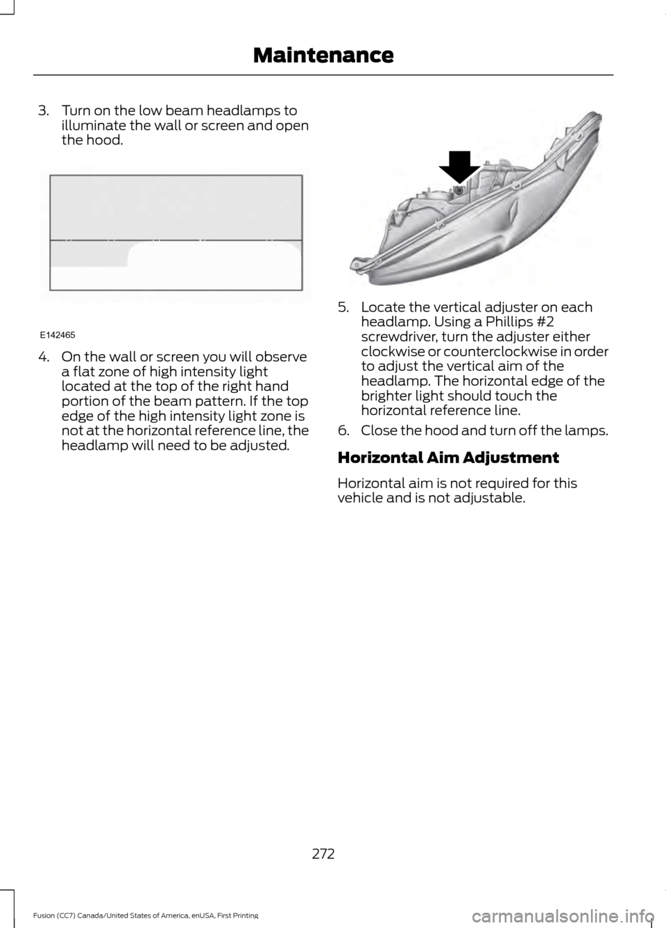
3. Turn on the low beam headlamps to
illuminate the wall or screen and open
the hood. 4. On the wall or screen you will observe
a flat zone of high intensity light
located at the top of the right hand
portion of the beam pattern. If the top
edge of the high intensity light zone is
not at the horizontal reference line, the
headlamp will need to be adjusted. 5. Locate the vertical adjuster on each
headlamp. Using a Phillips #2
screwdriver, turn the adjuster either
clockwise or counterclockwise in order
to adjust the vertical aim of the
headlamp. The horizontal edge of the
brighter light should touch the
horizontal reference line.
6. Close the hood and turn off the lamps.
Horizontal Aim Adjustment
Horizontal aim is not required for this
vehicle and is not adjustable.
272
Fusion (CC7) Canada/United States of America, enUSA, First Printing MaintenanceE142465 E145594