2017 FORD FUSION (AMERICAS) ECU
[x] Cancel search: ECUPage 271 of 528

Adding Transmission Fluid
*
1. Rotate the automatic transmission fluid cap in a counterclockwise
direction. *
2. Remove the cap and dipstick and wipe
it with a clean, lint-free cloth.
3. Add fluid that meets the Ford specifications. See Capacities and
Specifications (page 340). Pour the
fluid directly into the automatic
transmission fluid cap and dipstick
hole.
4. Replace the cap and dipstick and remove it again to check the fluid level.
5. Make sure that the fluid level is between the MIN and the MAX marks.
6. Replace the automatic transmission fluid cap and dipstick. Turn it clockwise
until you feel a strong resistance.
* Vehicles With 2.7L EcoBoost WARNING
Do not run the engine with the air
filter disconnected. 1. Remove the two air filter assembly
securing bolts.
2. Lift the air filter assembly to disengage
the locating pins.
3. Rotate the air filter assembly slightly in a counterclockwise direction.
4. Check the fluid level. See
Checking
the Transmission Fluid Level.
5. Install in reverse order. Tighten the two
air filter assembly securing bolts until
you feel a strong resistance.
BRAKE FLUID CHECK
Fluid levels between the MIN and MAX
lines are within the normal operating range;
there is no need to add fluid. If the fluid
levels are outside of the normal operating
range, the performance of the system
could be compromised; seek service from
your authorized dealer immediately.
268
Fusion (CC7) Canada/United States of America, enUSA, First Printing MaintenanceE190367
x2
Page 276 of 528

REMOVING A HEADLAMP
Note:
To remove push pins, use a
flat-bladed screwdriver to pull up the center
release pin.
1. Make sure the headlamp control is in the off position and open the hood.
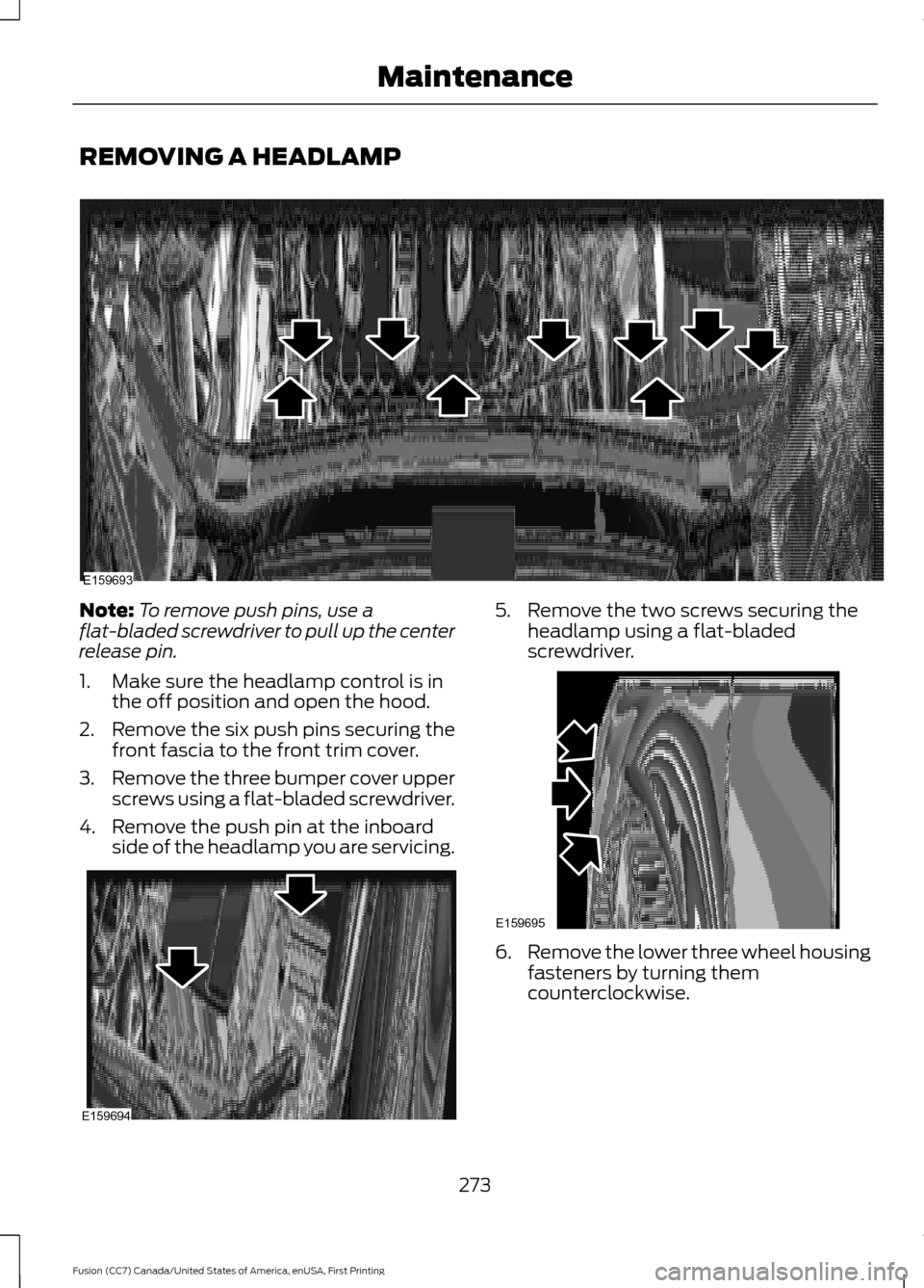
2. Remove the six push pins securing the
front fascia to the front trim cover.
3. Remove the three bumper cover upper
screws using a flat-bladed screwdriver.
4. Remove the push pin at the inboard side of the headlamp you are servicing. 5. Remove the two screws securing the
headlamp using a flat-bladed
screwdriver. 6.
Remove the lower three wheel housing
fasteners by turning them
counterclockwise.
273
Fusion (CC7) Canada/United States of America, enUSA, First Printing MaintenanceE159693 E159694 E159695
Page 281 of 528

CHANGING THE ENGINE AIR
FILTER
WARNING
To reduce the risk of vehicle damage
and/or personal burn injuries do not
start your engine with the air cleaner
removed and do not remove it while the
engine is running. When changing the air filter element, use
only the air filter element listed. See
Capacities and Specifications (page
321).
For EcoBoost equipped vehicles: When
servicing the air cleaner, it is important that
no foreign material enter the air induction
system. The engine and turbocharger are
susceptible to damage from even small
particles.
Change the air filter element at the proper
interval. See
Scheduled Maintenance
(page 477).
Note: Failure to use the correct air filter
element may result in severe engine
damage. The customer warranty may be
void for any damage to the engine if the
correct air filter element is not used.
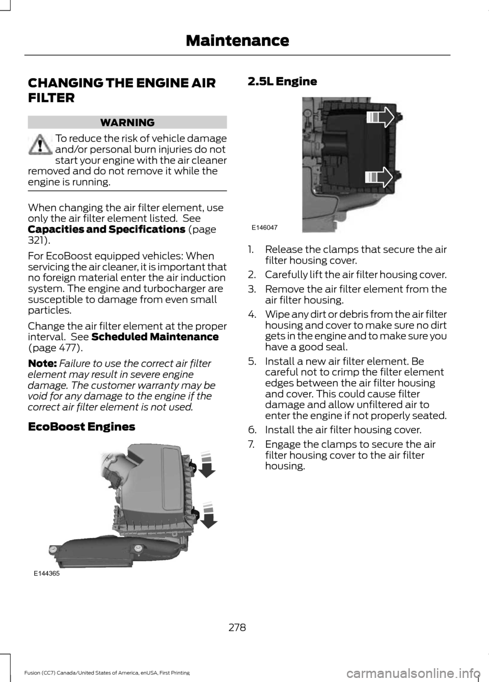
EcoBoost Engines 2.5L Engine
1.
Release the clamps that secure the air
filter housing cover.
2. Carefully lift the air filter housing cover.
3. Remove the air filter element from the
air filter housing.
4. Wipe any dirt or debris from the air filter
housing and cover to make sure no dirt
gets in the engine and to make sure you
have a good seal.
5. Install a new air filter element. Be careful not to crimp the filter element
edges between the air filter housing
and cover. This could cause filter
damage and allow unfiltered air to
enter the engine if not properly seated.
6. Install the air filter housing cover.
7. Engage the clamps to secure the air filter housing cover to the air filter
housing.
278
Fusion (CC7) Canada/United States of America, enUSA, First Printing MaintenanceE144365 E146047
Page 290 of 528

General Information
WARNING
Failure to follow these guidelines
could result in an increased risk of
loss of vehicle control, injury or death.
Note:
Do not use the kit if a tire has become
severely damaged. Only punctures located
within the tire tread can be sealed with the
kit.
Do not attempt to repair punctures larger
than ¼ inch (6 millimeters) or damage to
the tire's sidewall. The tire may not
completely seal.
Loss of air pressure may adversely affect
tire performance. For this reason:
Note: Do not drive the vehicle above
50 mph (80 km/h).
Note: Do not drive further than
120 mi
(200 km). Drive only to the closest
authorized Ford dealer or tire repair shop to
have your tire inspected.
• Drive carefully and avoid abrupt
steering maneuvers.
• Periodically monitor tire inflation
pressure in the affected tire; if the tire
is losing pressure, have the vehicle
towed.
• Read the information in the Tips for
Use of the Kit section to make sure safe
operation of the kit and your vehicle.
Tips for Use of the Kit
To ensure safe operation of the kit:
• Read all instructions and cautions fully.
• Before operating the kit, make sure
your vehicle is safely off the road and
away from moving traffic. Turn on the
hazard lights.
• Always set the parking brake to ensure
the vehicle doesn't move unexpectedly. •
Do not remove any foreign objects,
such as nails or screws, from the tire.
• When using the kit, leave the engine
running (only if the vehicle is outdoors
or in a well-ventilated area) so the
compressor does not drain the
vehicle's battery.
• Do not allow the compressor to
operate continuously for more than 15
minutes. This will help prevent the
compressor from overheating.
• Never leave the kit unattended during
operation.
• Sealant compound contains latex.
Those with latex sensitivities should
use appropriate precautions to avoid
an allergic reaction.
• Keep the kit away from children.
• Only use the kit when the ambient
temperature is between
-22°F (-30°C)
and 158°F (70°C).
• Only use the sealing compound before
the use-by date. The use-by date is on
a label on the sealant canister and can
be seen through the rectangular
viewing window on the bottom of the
compressor. Check the use-by date
regularly and replace the canister after
four years of non-use.
• Do not store the kit unsecured inside
the passenger compartment of the
vehicle as it may cause injury during a
sudden stop or crash. Always store the
kit in its original location.
• After sealant use, the tire pressure
monitoring system sensor and valve
stem on the wheel must be replaced
by an authorized Ford dealer.
• Operating the kit could cause an
electrical disturbance in radio, CD, and
DVD player operation.
287
Fusion (CC7) Canada/United States of America, enUSA, First Printing Wheels and Tires
Page 291 of 528

* When inflation only is required
for a tire or other objects, the
selector must be in the Air
position.
What to do when a Tire Is
Punctured
A tire puncture within the tire's tread area
can be repaired in two stages with the kit.
• In the first stage, the tire will be
reinflated with a sealing compound
and air. After the tire has been inflated,
you will need to drive the vehicle a
short distance (about 4 miles [6
kilometers]) to distribute the sealant
in the tire.
• In the second stage, you will need to
check the tire pressure and adjust, if
necessary, to the vehicle's specified
tire inflation pressure.
First Stage: Reinflating the Tire
with Sealing Compound and Air WARNINGS
Do not stand directly over the kit
while inflating the tire. If you notice
any unusual bulges or deformations
in the tire's sidewall during inflation, stop
and call roadside assistance. If the tire does not inflate to the
recommended tire pressure within
15 minutes, stop and call roadside
assistance. Do not run the engine during kit
operation unless the vehicle is
outdoors or in a well-ventilated area.
Preparation: Park the vehicle in a safe, level
and secure area, away from moving traffic.
Turn the hazard lights on. Apply the parking
brake and turn the engine off. Inspect the
flat tire for visible damage. Sealant compound contains latex. Use
appropriate precautions to avoid any
allergic reactions.
Do not remove any foreign object that has
pierced the tire. If a puncture is located in
the tire sidewall, stop and call roadside
assistance.
1. Remove the valve cap from the tire
valve.
2. Unwrap the dual purpose hose (black tube) from the back of the compressor
housing.
3. Fasten the hose to the tire valve by turning the connector clockwise.
Tighten the connection securely. 4. Plug the power cable into the 12-volt
power point in the vehicle.
288
Fusion (CC7) Canada/United States of America, enUSA, First Printing Wheels and TiresE175978 E175979
Page 317 of 528

Changing a Road Wheel Procedure
(If Equipped)
WARNINGS
When one of the front wheels is off
the ground, the transmission alone
will not prevent the vehicle from
moving or slipping off the jack, even if the
transmission is in park (P). To help prevent your vehicle from
moving when you change a tire, be
sure to place the transmission in park
(P), set the parking brake and block (in
both directions) the wheel that is
diagonally opposite (other side and end of
the vehicle) to the tire being changed. Never get underneath a vehicle that
is supported only by a jack. If your
vehicle slips off the jack, you or
someone else could be seriously injured. Do not attempt to change a tire on
the side of the vehicle close to
moving traffic. Pull far enough off the
road to avoid the danger of being hit when
operating the jack or changing the wheel. Always use the jack provided as
original equipment with your vehicle.
If using a jack other than the one
provided as original equipment with your
vehicle, make sure the jack capacity is
adequate for the vehicle weight, including
any vehicle cargo or modifications. Note:
Passengers should not remain in your
vehicle when the vehicle is being jacked.
1. Park on a level surface, set the parking
brake and activate the hazard flashers.
2. Place the transmission in park (P) and
turn the engine off. For vehicles with a
manual transmission, place the
transmission in reverse ®) after the
engine is turned off. 3. Block both the front and rear of the
wheel diagonally opposite the flat tire.
For example, if the left front tire is flat,
block the right rear wheel.
4. Remove the carpeted wheel cover.
5. Remove the spare tire bolt securing the
spare tire by turning it
counterclockwise.
6. Remove the spare tire from the spare tire compartment. 7. Remove the lug wrench and jack from
the spare tire compartment.
314
Fusion (CC7) Canada/United States of America, enUSA, First Printing Wheels and TiresE175447 E178186
Page 320 of 528

17. To store the folded wrench on the
jack, engage the bracket of the jack
base on the wrench feature as shown.
Swing the wrench upward and adjust
the height of the jack until the pin
engages the hole. Tighten the hex nut
clockwise by hand until secure.
18. Put the flat tire, jack and lug wrench away. Make sure the jack is fastened
securely before you drive.
19. Unblock the wheel.
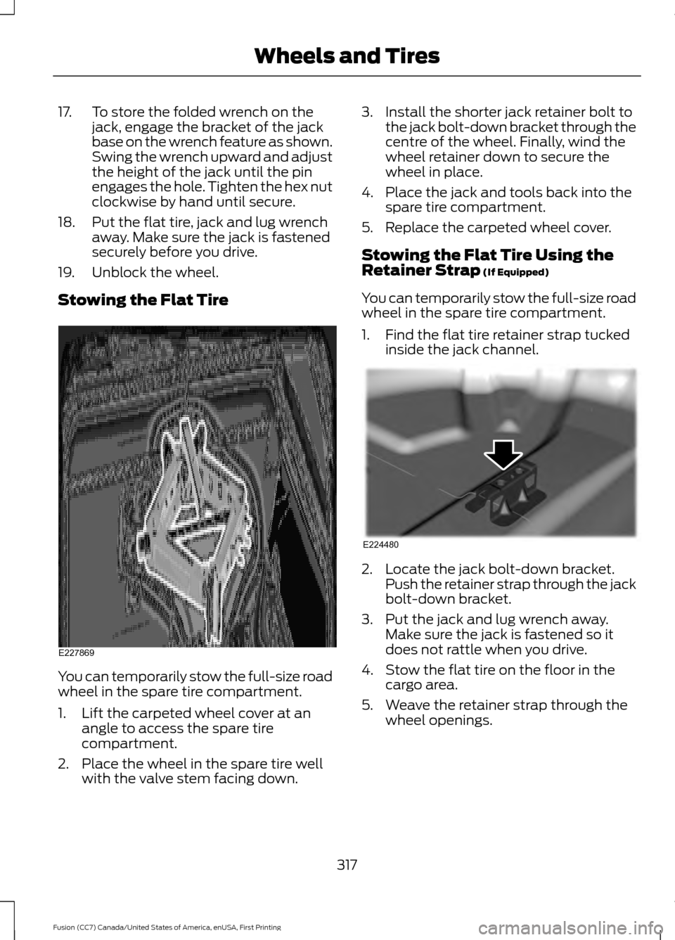
Stowing the Flat Tire You can temporarily stow the full-size road
wheel in the spare tire compartment.
1. Lift the carpeted wheel cover at an
angle to access the spare tire
compartment.
2. Place the wheel in the spare tire well with the valve stem facing down. 3. Install the shorter jack retainer bolt to
the jack bolt-down bracket through the
centre of the wheel. Finally, wind the
wheel retainer down to secure the
wheel in place.
4. Place the jack and tools back into the spare tire compartment.
5. Replace the carpeted wheel cover.
Stowing the Flat Tire Using the
Retainer Strap (If Equipped)
You can temporarily stow the full-size road
wheel in the spare tire compartment.
1. Find the flat tire retainer strap tucked inside the jack channel. 2. Locate the jack bolt-down bracket.
Push the retainer strap through the jack
bolt-down bracket.
3. Put the jack and lug wrench away. Make sure the jack is fastened so it
does not rattle when you drive.
4. Stow the flat tire on the floor in the cargo area.
5. Weave the retainer strap through the wheel openings.
317
Fusion (CC7) Canada/United States of America, enUSA, First Printing Wheels and TiresE227869 E224480
Page 321 of 528

6. Secure the flat tire by tying a flat knot.
TECHNICAL SPECIFICATIONS - 1.5L ECOBOOST™/2.0L
ECOBOOST™/2.5L
Wheel Lug Nut Torque Specifications WARNING
When a wheel is installed, always remove any corrosion, dirt or foreign materials
present on the mounting surfaces of the wheel or the surface of the wheel hub,
brake drum or brake disc that contacts the wheel. Make sure that any fasteners
that attach the rotor to the hub are secured so they do not interfere with the mounting
surfaces of the wheel. Installing wheels without correct metal-to-metal contact at the
wheel mounting surfaces can cause the wheel nuts to loosen and the wheel to come off
while your vehicle is in motion, resulting in loss of control. Ib-ft (Nm)
*
Bolt size
100 (135)
M12 x 1.5
* Torque specifications are for nut and bolt threads free of dirt and rust. Use only Ford
recommended replacement fasteners.
Retighten the lug nuts to the specified torque within 100 miles (160 kilometers) after any
wheel disturbance (such as tire rotation, changing a flat tire, wheel removal).
318
Fusion (CC7) Canada/United States of America, enUSA, First Printing Wheels and TiresE224479