2017 FORD FUSION (AMERICAS) display
[x] Cancel search: displayPage 218 of 528

If a message regarding a blocked sensor
or camera appears in the information
display, the radar signals or camera images
are obstructed. The radar sensor is located
behind a fascia cover near the driver side
of the lower grille. With an obstructed
radar, the Pre-Collision Assist system does
not function and cannot detect a vehicle
ahead. With the front camera obstructed,
the Pre-Collision Assist system does not
respond to pedestrians or stationary
vehicles and the system performance on
moving vehicles reduces. The following
table lists possible causes and actions for
when this message displays. Action
Cause
Clean the grille surface in front of the radaror remove the object causing the obstruc- tion.
The surface of the radar in the grille is dirty
or obstructed in some way.
Wait a short time. It may take several
minutes for the radar to detect that there is no obstruction.
The surface of the radar in the grille is clean
but the message remains in the display.
The Pre-Collision Assist system is tempor-arily disabled. Pre-Collision Assist should
automatically reactivate a short time after the weather conditions improve.
Heavy rain, spray, snow, or fog is interfering
with the radar signals.
The Pre-Collision Assist system is tempor-arily disabled. Pre-Collision Assist should
automatically reactivate a short time after the weather conditions improve.
Swirling water, or snow or ice on the surface
of the road may interfere with the radar signals.
Contact an authorized dealer to have theradar checked for proper coverage and operation.
Radar is out of alignment due to a front end
impact.
Clean the outside of the windshield in frontof the camera.
The windshield in front of the camera is
dirty or obstructed in some way.
Wait a short time. It may take several
minutes for the camera to detect that there is no obstruction.
The windshield in front of the camera is
clean but the message remains in the display.
Note: Proper system operation requires a
clear view of the road by the camera. Have
any windshield damage in the area of the
camera's field of view repaired. Note:
If something hits the front end of your
vehicle or damage occurs, the radar sensing
zone may change. This could cause missed
or false vehicle detections. Contact an
authorized dealer to have the radar checked
for proper coverage and operation.
215
Fusion (CC7) Canada/United States of America, enUSA, First Printing Driving Aids
Page 219 of 528

Note:
If your vehicle detects excessive heat
at the camera or a potential misalignment
condition, a message may display in the
information display indicating temporary
sensor unavailability. This message
deactivates automatically when operational
conditions are corrected (for example, when
the ambient temperature around the sensor
decreases or the sensor automatically
recalibrates successfully).
216
Fusion (CC7) Canada/United States of America, enUSA, First Printing Driving Aids
Page 230 of 528

2.
Select the neutral tow option under the
vehicle settings menu in the
information display. See General
Information (page 93).
3. Press and hold the OK button to start the neutral tow process.
4. Press the brake pedal and select N on the rotary shift transmission.
5. Turn the ignition off by pressing the engine START button without pressing
the brake pedal.
If the process completes successfully:
• the N on the rotary shift transmission
blinks slowly.
• A confirmation message appears in the
information display.
Note: If the parking brake is applied, a
message appears in the information display.
Note: Do not exceed 65 mph (105 km/h).
Note: Start the engine and allow it to run
for five minutes at the beginning of each day
and every six hours (or fewer). Shut the
engine off and verify that a message
appears indicating neutral tow has been
engaged, before continuing to tow.
Exit Neutral Tow mode, make sure the
ignition is on (engine can be on or off),
press the brake pedal and select P on the
rotary shift transmission.
If the process is completed successfully,
a message appears indicating that neutral
tow has disengaged in both the instrument
cluster and rotary shift transmission
display P.
227
Fusion (CC7) Canada/United States of America, enUSA, First Printing Towing
Page 238 of 528

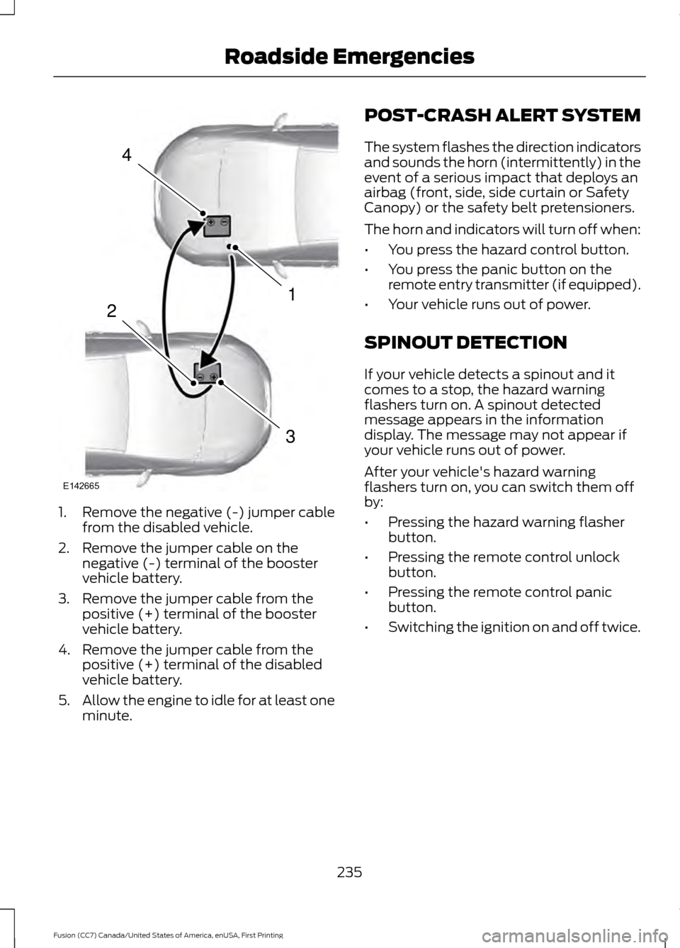
1. Remove the negative (-) jumper cable
from the disabled vehicle.
2. Remove the jumper cable on the negative (-) terminal of the booster
vehicle battery.
3. Remove the jumper cable from the positive (+) terminal of the booster
vehicle battery.
4. Remove the jumper cable from the positive (+) terminal of the disabled
vehicle battery.
5. Allow the engine to idle for at least one
minute. POST-CRASH ALERT SYSTEM
The system flashes the direction indicators
and sounds the horn (intermittently) in the
event of a serious impact that deploys an
airbag (front, side, side curtain or Safety
Canopy) or the safety belt pretensioners.
The horn and indicators will turn off when:
•
You press the hazard control button.
• You press the panic button on the
remote entry transmitter (if equipped).
• Your vehicle runs out of power.
SPINOUT DETECTION
If your vehicle detects a spinout and it
comes to a stop, the hazard warning
flashers turn on. A spinout detected
message appears in the information
display. The message may not appear if
your vehicle runs out of power.
After your vehicle's hazard warning
flashers turn on, you can switch them off
by:
• Pressing the hazard warning flasher
button.
• Pressing the remote control unlock
button.
• Pressing the remote control panic
button.
• Switching the ignition on and off twice.
235
Fusion (CC7) Canada/United States of America, enUSA, First Printing Roadside Emergencies4
1
3
2
E142665
Page 250 of 528

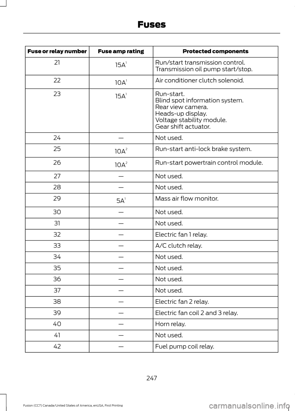
Protected components
Fuse amp rating
Fuse or relay number
Run/start transmission control.
15A 1
21
Transmission oil pump start/stop.
Air conditioner clutch solenoid.
10A 1
22
Run-start.
15A 1
23
Blind spot information system.
Rear view camera.
Heads-up display.
Voltage stability module.
Gear shift actuator.
Not used.
—
24
Run-start anti-lock brake system.
10A 2
25
Run-start powertrain control module.
10A 2
26
Not used.
—
27
Not used.
—
28
Mass air flow monitor.
5A 1
29
Not used.
—
30
Not used.
—
31
Electric fan 1 relay.
—
32
A/C clutch relay.
—
33
Not used.
—
34
Not used.
—
35
Not used.
—
36
Not used.
—
37
Electric fan 2 relay.
—
38
Electric fan coil 2 and 3 relay.
—
39
Horn relay.
—
40
Not used.
—
41
Fuel pump coil relay.
—
42
247
Fusion (CC7) Canada/United States of America, enUSA, First Printing Fuses
Page 257 of 528

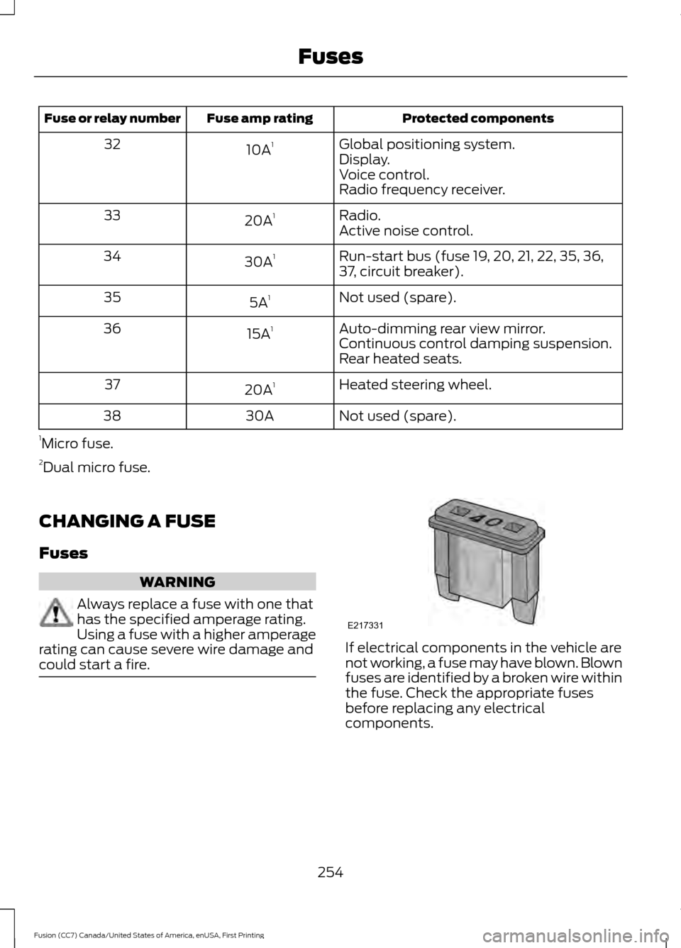
Protected components
Fuse amp rating
Fuse or relay number
Global positioning system.
10A 1
32
Display.
Voice control.
Radio frequency receiver.
Radio.
20A 1
33
Active noise control.
Run-start bus (fuse 19, 20, 21, 22, 35, 36,
37, circuit breaker).
30A
1
34
Not used (spare).
5A 1
35
Auto-dimming rear view mirror.
15A 1
36
Continuous control damping suspension.
Rear heated seats.
Heated steering wheel.
20A 1
37
Not used (spare).
30A
38
1 Micro fuse.
2 Dual micro fuse.
CHANGING A FUSE
Fuses WARNING
Always replace a fuse with one that
has the specified amperage rating.
Using a fuse with a higher amperage
rating can cause severe wire damage and
could start a fire. If electrical components in the vehicle are
not working, a fuse may have blown. Blown
fuses are identified by a broken wire within
the fuse. Check the appropriate fuses
before replacing any electrical
components.
254
Fusion (CC7) Canada/United States of America, enUSA, First Printing FusesE217331
Page 265 of 528

Do not use supplemental engine oil
additives because they are unnecessary
and could lead to engine damage that may
not be covered by the vehicle Warranty.
Only use oils certified for gasoline engines
by the American Petroleum Institute (API).
An oil with this trademark symbol
conforms to the current engine and
emission system protection standards and
fuel economy requirements of the
International Lubricants Specification
Advisory Committee (ILSAC), comprised
of U.S. and Japanese automobile
manufacturers.
To top up the engine oil level do the
following:
Clean the area surrounding the engine oil
filler cap before you remove it.
1. Remove the engine oil filler cap. See
Under Hood Overview (page 257).
Turn it counterclockwise and remove
it.
2. Add engine oil that meets the correct specification. See
Capacities and
Specifications (page 330). You may
have to use a funnel to pour the engine
oil into the opening.
3. Recheck the oil level.
4. If the oil level is correct, replace the dipstick and make sure it is fully seated. 5. Replace the engine oil filler cap. Turn
it clockwise until you feel a strong
resistance.
Note: Do not add oil further than the
maximum mark. Oil levels above the
maximum mark may cause engine damage.
Note: Make sure you install the oil filler cap
correctly.
Note: Soak up any spillage with an
absorbent cloth immediately.
OIL CHANGE INDICATOR
RESET
Use the information display controls on
the steering wheel to reset the oil change
indicator.
From the main menu scroll to: Action and description
Message
Press the right arrow button,
then from this menu scroll
to the following message.
Settings
Press the right arrow button,
then from this menu scroll
to the following message.
Vehicle
Press the right arrow button,
then from this menu scroll
to the following message.
Oil Life
Press and hold the
OK
button until the instrument
cluster displays the
following message.
Hold OK to
Reset
Reset Successful
When the oil change indic-
ator resets the instrument
cluster displays 100%.
Remaining Life
{00}%
262
Fusion (CC7) Canada/United States of America, enUSA, First Printing MaintenanceE142732
Page 266 of 528

Action and description
Message
If the instrument cluster
displays one of the following
messages, repeat the
process.
Not Reset
Reset Cancelled
ENGINE COOLANT CHECK WARNINGS
Do not add engine coolant when the
engine is hot. Steam and scalding
liquids released from a hot cooling
system can burn you badly. Also, spilling
coolant on hot engine parts can burn you. Do not put engine coolant in the
windshield washer fluid container. If
sprayed on the windshield, engine
coolant could make it difficult to see
through the windshield. To reduce the risk of personal injury,
make sure the engine is cool before
unscrewing the coolant pressure
relief cap. The cooling system is under
pressure. Steam and hot liquid can come
out forcefully when you loosen the cap
slightly. Do not add coolant further than the
MAX mark.
When the engine is cold, check the
concentration and level of the coolant at
the intervals listed in the scheduled
maintenance information. See Scheduled
Maintenance
(page 477).
Note: Make sure that the coolant level is
between the
MIN and MAX marks on the
coolant reservoir.
Note: Coolant expands when it is hot. The
level may extend beyond the
MAX mark. Maintain coolant concentration within
48% to 50%, which equates to a freeze
point between -30°F (-34°C) and -34°F
(-37°C). Coolant concentration should be
checked using a refractometer. We
recommend, Robinair® Coolant and
Battery Refractometer 75240 (Rotunda
tool part number: ROB75240). We do not
recommend the use of hydrometers or
coolant test strips for measuring coolant
concentration.
Note:
Automotive fluids are not
interchangeable. Do not use coolant or
windshield washer fluid outside of its
specified function and vehicle location.
Note: Do not use stop leak pellets, cooling
system sealants, or non-specified additives
as they can cause damage to the engine
cooling or heating systems. Resulting
component damage may not be covered by
the vehicle Warranty.
Adding Coolant WARNING
Never remove the coolant reservoir
cap while the engine is running or hot.
It is very important to use prediluted
coolant meeting the correct specification
in order to avoid plugging the small
passageways in the engine cooling system.
See
Capacities and Specifications
(page 330). Incorrect prediluted coolant
use can cause damage not covered by the
vehicle Warranty.
If the coolant level is at or below the
minimum mark, add prediluted coolant
immediately.
To top up the coolant level do the
following:
1. Unscrew the cap slowly. Any pressure escapes as you unscrew the cap.
263
Fusion (CC7) Canada/United States of America, enUSA, First Printing Maintenance