2017 FORD F450 SUPER DUTY steering
[x] Cancel search: steeringPage 260 of 642
If the power steering system breaks down(or if the engine is turned off), you cansteer the vehicle manually, but it takesmore effort.
If the steering wanders or pulls, check for:
•an improperly inflated tire
•uneven tire wear
•loose or worn suspension components
•loose or worn steering components
•improper vehicle alignment
If any steering components are serviced orreplaced, install new fasteners (many arecoated with thread adhesive or haveprevailing torque features which may notbe re-used). Never re-use a bolt or nut.Torque fasteners to specifications.
A high crown in the road or high crosswindsmay also make the steering seem towander or pull.
Adaptive Steering (If Equipped)
WARNING
The adaptive steering system hasdiagnostic checks that continuouslymonitor the system. If a fault isdetected a message displays in theinformation display. Stop your vehicle assoon as it is safe to do so. This warningmessage may clear if the fault is no longerpresent. If an adaptive steering systemwarning message appears each time youstart your vehicle, have the systemchecked as soon as possible.
The adaptive steering system continuallychanges the steering ratio with changes tovehicle speed, optimizing the steeringresponse in all conditions. The system alsochanges when you switch on thetransmission tow/haul feature. When youselect the tow/haul button, the adaptivesteering system reduces vehicle sensitivityto steering inputs at higher vehicle speeds,while maintaining the ease of parking andmaneuverability at low speeds.
Note:The adaptive steering system isdesigned with a locking device. With thelock engaged, the adaptive steering systemremains mechanically locked at a fixedsteering ratio. You may also notice a clickwhen you switch the vehicle on or after youswitch it off, as the lock disengages orengages.
Note:If your vehicle loses electrical poweror detects a fault when you are driving, thesystem automatically shuts down and youretain normal steering function with a fixedsteering ratio. During this time it is possiblethat the steering wheel may not be straightwhen the vehicle is driving straight ahead.In addition, the driver may notice that thesteering wheel angle required to steer thevehicle may be different.
Note:During parking maneuvers, theadaptive steering system balances the driverwork load for various steering wheel inputsand vehicle loading conditions. Underextreme operating conditions the systemlocking device may engage. This strategyprevents overheating and permanentdamage to the adaptive steering system.Typical steering and driving maneuversallow the system to cool and return tonormal operation.
257
Super Duty (TFE) Canada/United States of America, enUSA, Edition date: 201710, Second Printing
Driving Aids
Page 263 of 642

System Limitations
WARNING
The collision warning system’s brakesupport only reduces collision speedif you first apply your brakes. Youmust brake as you would in any typicalbraking situation.
Due to the nature of radar technology,there may be certain instances wherevehicles do not provide a collision warning.These include:
•Stationary vehicles or vehicles movingbelow 6 mph (10 km/h).
•Pedestrians or objects in the roadway.
•Oncoming vehicles in the same lane.
•Severe weather conditions (seeblocked sensor section).
•Debris build-up on the grille near theheadlamps (see blocked sensorsection).
•Small distance to vehicle ahead.
•Large steering wheel and pedalmovements (very active driving style).
Damage to the front end of your vehiclemay alter the radar sensor's coverage area.This may result in missed or false collisionwarnings. Have an authorized dealer checkyour radar sensor for proper coverage andoperation.
260
Super Duty (TFE) Canada/United States of America, enUSA, Edition date: 201710, Second Printing
Driving Aids
Page 273 of 642
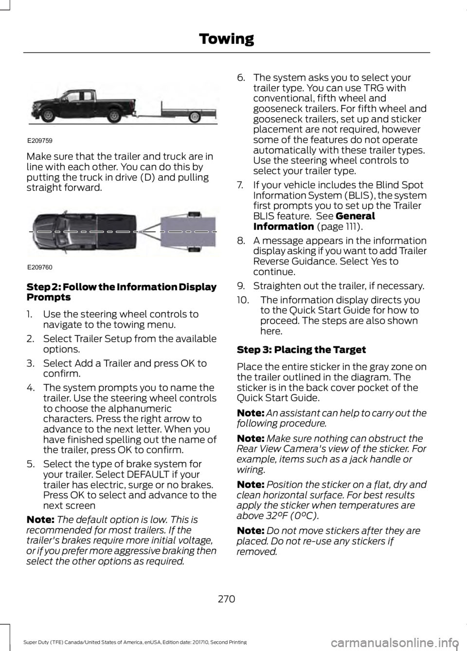
Make sure that the trailer and truck are inline with each other. You can do this byputting the truck in drive (D) and pullingstraight forward.
Step 2: Follow the Information DisplayPrompts
1. Use the steering wheel controls tonavigate to the towing menu.
2.Select Trailer Setup from the availableoptions.
3. Select Add a Trailer and press OK toconfirm.
4. The system prompts you to name thetrailer. Use the steering wheel controlsto choose the alphanumericcharacters. Press the right arrow toadvance to the next letter. When youhave finished spelling out the name ofthe trailer, press OK to confirm.
5. Select the type of brake system foryour trailer. Select DEFAULT if yourtrailer has electric, surge or no brakes.Press OK to select and advance to thenext screen
Note:The default option is low. This isrecommended for most trailers. If thetrailer's brakes require more initial voltage,or if you prefer more aggressive braking thenselect the other options as required.
6. The system asks you to select yourtrailer type. You can use TRG withconventional, fifth wheel andgooseneck trailers. For fifth wheel andgooseneck trailers, set up and stickerplacement are not required, howeversome of the features do not operateautomatically with these trailer types.Use the steering wheel controls toselect your trailer type.
7. If your vehicle includes the Blind SpotInformation System (BLIS), the systemfirst prompts you to set up the TrailerBLIS feature. See GeneralInformation (page 111).
8. A message appears in the informationdisplay asking if you want to add TrailerReverse Guidance. Select Yes tocontinue.
9. Straighten out the trailer, if necessary.
10. The information display directs youto the Quick Start Guide for how toproceed. The steps are also shownhere.
Step 3: Placing the Target
Place the entire sticker in the gray zone onthe trailer outlined in the diagram. Thesticker is in the back cover pocket of theQuick Start Guide.
Note:An assistant can help to carry out thefollowing procedure.
Note:Make sure nothing can obstruct theRear View Camera's view of the sticker. Forexample, items such as a jack handle orwiring.
Note:Position the sticker on a flat, dry andclean horizontal surface. For best resultsapply the sticker when temperatures areabove 32°F (0°C).
Note:Do not move stickers after they areplaced. Do not re-use any stickers ifremoved.
270
Super Duty (TFE) Canada/United States of America, enUSA, Edition date: 201710, Second Printing
TowingE209759 E209760
Page 275 of 642
Step 5: Enter Measurements Using theInformation Display
Using the recorded measurements, enterthe required data into the system. Followthe on screen prompts to enter each of themeasurements taken in step 4. Use theup/down arrows to increase or decreasethe numbers as needed. Press OK toconfirm each measurement. The screenprompts you to add the nextmeasurement. Once you add your lastmeasurement, the information displayshows you all of your enteredmeasurements. You can choose to confirmor change the measurements.
Step 6: Confirming the Sticker Location
Check the Rear View Camera display tosee if the sticker is identified by the systemand marked with a red circle.
Confirm that the red circle is correctlylocated over the sticker image in thedisplay. The on screen prompt will ask youto confirm this.
Note:If the system cannot locate thesticker try cleaning the camera lens, andalso make sure the sticker is within the zoneas indicated in step 3.
The information display shows aconfirmation message when yousuccessfully confirm the target.
Calibrating the System
To complete setup, drive your vehiclestraight forward between 4 mph (6 km/h)and 24 mph (39 km/h) as directed by theinformation display.
Note:Keep the steering wheel straightduring the calibration process. If the steeringwheel is in a turned position, then thecalibration pauses. The information displayprompts you to drive straight forward tocomplete the calibration.
The information display shows a messageduring calibration and after calibration iscomplete
Note:For best results, we do notrecommend that you calibrate the systemat night.
Using Trailer Reverse Guidance
1. Shift into reverse (R) if you are notalready in reverse. Press the rearcamera button to expand the menu.
2. Press the trailer icon .
3. Select your trailer on your informationdisplay.
4. While in TRG mode, you can see thecamera view on the side where yourtrailer is moving, or both sides whenthe trailer is straight behind you. Whenthe views change with the trailerdirection, it's called Auto Mode. Forexample, If you turn the trailer to theright, then you see the right side of yourvehicle and trailer. You can switch thisview manually at any time by using thearrow keys. To return to Auto Mode,press the Auto button.
Note:Auto Mode is your default setting.
Use the view that helps you the most whilebacking up your vehicle and trailer.
Normal rear view camera view.Use this feature when you wantto see your trailer hitch or whatis directly behind your vehicle.
Straight back-up mode. Use thisfeature when you want to keepyour trailer completely in linewith your truck. In this mode, a steeringwheel graphic shows you which way to turnyour steering wheel to keep your trailerstraight.
272
Super Duty (TFE) Canada/United States of America, enUSA, Edition date: 201710, Second Printing
TowingE224483 E224484
Page 276 of 642
Note: It may be helpful to shift your vehicleinto drive (D), pull forward and straightenout the vehicle and trailer before engagingStraight Backup Mode.
Left and right arrows let you see otherviews regardless of your trailer angle. Usethem to switch views manually.
Note: If you're using a Fifth Wheel orGooseneck trailer, or you haven't set up theTrailer Reverse Guidance System yet, AutoView is not available.
To change your view, use the arrows. Youcan see the following views:
•Full driver
•Partial driver
•50/50
•Partial passenger
•Full passenger
Zoom. Use this feature to zoomin on any view.
Return. Ths feature takes youback to the 360-degree camerasystem and out of the TrailerReverse Guidance feature.
Auto. Ths feature returns you toautomatic view mode.
In addition to multiple view options, yourtouchscreen adds some features to giveyou more information.
After using the set up for a conventionaltrailer, for example, the display alwaysshows you a small, top-viewrepresentation of your truck and trailer.
This representation shows two,different-colored lines: A black line showsyou where your trailer is in relation to yourvehicle. A white line gives you a projectionof where your trailer will go based on yourcurrent steering wheel position
Note:When you move the steering wheel,the white line indicates where the trailer willgo based on your steering wheel input.
When you turn your steering wheel to theleft, the trailer moves to the right; when youturn your steering wheel to the right, thetrailer moves to the left.
When you turn the wheel, the smallrepresentation shows you two zones towarn you of a possible jackknife condition.The view shows you your truck and trailerposition and provides visual feedback tohelp you avoid jackknifing entirely.
The yellow zone warns you of a potentialjackknife position. When you enter into thiszone, it's best to put your vehicle back intodrive (D) and pull forward. Moving forwardhelps put the truck and trailer back into anin-line position.
The RED zone indicates that you need toput the truck into drive (D) and pullforward immediately.
Troubleshooting
Note:The system requires a clear view ofthe sticker placed on the trailer. You mustkeep the camera lens and sticker clean forthe system to operate correctly.
Setup
The system is designed to be used with awide variety of trailers. However there aresome trailers that do not have a propersurface and location to mount the sticker.These trailers are not supported. Attemptsto place the sticker on a surface that doesnot meet the sticker placementrequirement listed in Step 3 of the setupinstruction or entering inaccuratemeasurements to proceed through setupcan result in improper system function.
273
Super Duty (TFE) Canada/United States of America, enUSA, Edition date: 201710, Second Printing
TowingE224485 E224487 E224486
Page 278 of 642
Measurement D has reached maximum orminimum value:
•Make sure that the measurement beingmade is the horizontal distance onlyfrom tailgate to the center of the singleaxle or the center of all the axles on thetrailer. See step 4 of the setup foradditional measurement instructions.The TBA system does not supporttrailer lengths outside the rangeallowed by the information display.
System is circling something beside thesticker or system cannot find the sticker:
•Make sure the rear camera is clean andthe sticker is clearly visible in thecamera image. Clean the camera andsticker if necessary.
•The camera system uses the enteredmeasurements to help locate thesticker. Inaccurate stickermeasurements will degrade thesystem’s ability to locate the sticker.Verify the measurements entered intothe system are accurate.
•Remove the incorrectly circled label ordecal if possible.
•If you cannot resolve the issue a newsticker location should be tried. Thesticker location must still meet therequirements noted in step 3 of thesetup instructions. Only one sticker canbe placed on the trailer for correctsystem function. The previous stickermust be removed or covered so onlyone sticker is visible to the camera.
Calibration
The system monitors various vehicleparameters to ensure your vehicle is beingdriven straight and the trailer straightbehind your vehicle. Any steering input ortrailer movement will pause the calibration.
For best results:
•Use a long, straight and smooth roadwhen attempting to calibrate.
•Drive straight forward.
•Drive between 4 mph (6 km/h) and24 mph (39 km/h).
System Operation
The following warnings or difficulties mayoccur during feature operation. Tips toresolve them are listed below.
The system is not available:
•The system relies on manysub-systems in your vehicle to operatecorrectly. If those sub-systems are notoperating correctly the system may notbe available.
•Low battery voltage is a conditionwhich will prevent the system fromoperating. Please make sure thebattery is correctly charged if thesystem is not available.
•You may need to drive your vehiclestraight forward above 25 mph(40 km/h) before the system isavailable again.
•If the message still displays take yourvehicle to an authorized dealer forservice.
275
Super Duty (TFE) Canada/United States of America, enUSA, Edition date: 201710, Second Printing
Towing
Page 285 of 642
When attaching the trailer wiring connectorto your vehicle, only use a proper fittingconnector that works with the vehicle andtrailer functions. Some seven-positionconnectors may have the SAE J2863 logo,which confirms that it is the proper wiringconnector and works correctly with yourvehicle.
FunctionColor
Left turn signal and stop lampYellow
Ground (-)White
Electric brakesBlue
Right turn signal and stoplampGreen
Battery (+)Orange
Running lightsBrown
Reverse lightsGrey
Dynamic Hitching Using the RearView Camera System
Note:Active guidelines and fixed guidelinesare only available when the transmission isin reverse (R).
Use the centerline (B) guideline to assistyou in setting your steering wheel properlyto help align the trailer hitch and tongue.
Active guidelinesA
CenterlineB
Fixed guideline: Green zoneC
Fixed guideline: Yellow zoneD
Fixed guideline: Red zoneE
Rear bumperF
Fixed guidelines are always shown in thedisplay, but the active guidelines onlydisplay when the steering wheel is turned.To use active guidelines, turn the steeringwheel to point the guidelines toward anintended path. If the steering wheelposition is changed while reversing, yourvehicle might deviate from the originalintended path.
282
Super Duty (TFE) Canada/United States of America, enUSA, Edition date: 201710, Second Printing
TowingABCD
F
E
E142436
Page 286 of 642
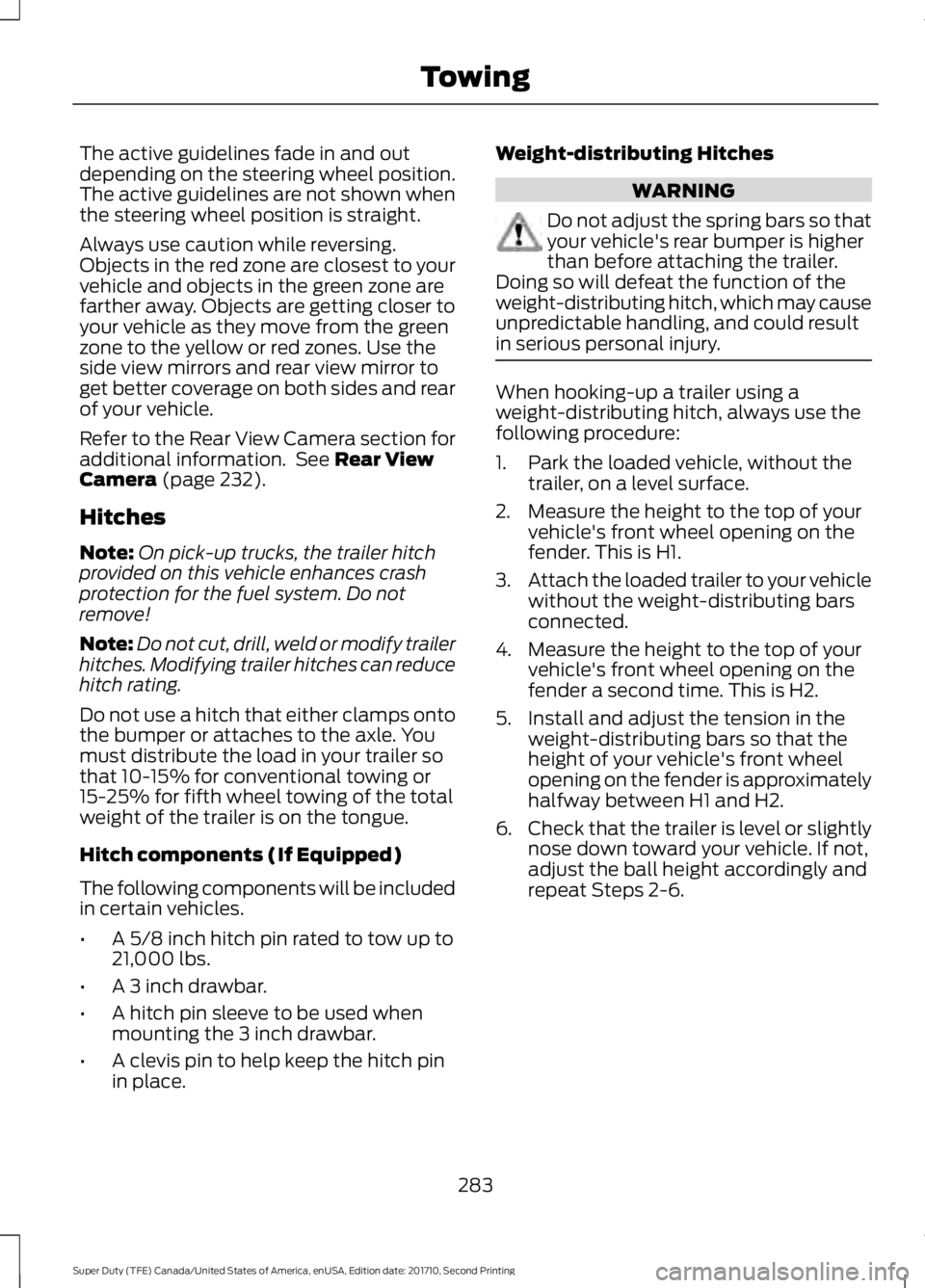
The active guidelines fade in and outdepending on the steering wheel position.The active guidelines are not shown whenthe steering wheel position is straight.
Always use caution while reversing.Objects in the red zone are closest to yourvehicle and objects in the green zone arefarther away. Objects are getting closer toyour vehicle as they move from the greenzone to the yellow or red zones. Use theside view mirrors and rear view mirror toget better coverage on both sides and rearof your vehicle.
Refer to the Rear View Camera section foradditional information. See Rear ViewCamera (page 232).
Hitches
Note:On pick-up trucks, the trailer hitchprovided on this vehicle enhances crashprotection for the fuel system. Do notremove!
Note:Do not cut, drill, weld or modify trailerhitches. Modifying trailer hitches can reducehitch rating.
Do not use a hitch that either clamps ontothe bumper or attaches to the axle. Youmust distribute the load in your trailer sothat 10-15% for conventional towing or15-25% for fifth wheel towing of the totalweight of the trailer is on the tongue.
Hitch components (If Equipped)
The following components will be includedin certain vehicles.
•A 5/8 inch hitch pin rated to tow up to21,000 lbs.
•A 3 inch drawbar.
•A hitch pin sleeve to be used whenmounting the 3 inch drawbar.
•A clevis pin to help keep the hitch pinin place.
Weight-distributing Hitches
WARNING
Do not adjust the spring bars so thatyour vehicle's rear bumper is higherthan before attaching the trailer.Doing so will defeat the function of theweight-distributing hitch, which may causeunpredictable handling, and could resultin serious personal injury.
When hooking-up a trailer using aweight-distributing hitch, always use thefollowing procedure:
1. Park the loaded vehicle, without thetrailer, on a level surface.
2. Measure the height to the top of yourvehicle's front wheel opening on thefender. This is H1.
3.Attach the loaded trailer to your vehiclewithout the weight-distributing barsconnected.
4. Measure the height to the top of yourvehicle's front wheel opening on thefender a second time. This is H2.
5. Install and adjust the tension in theweight-distributing bars so that theheight of your vehicle's front wheelopening on the fender is approximatelyhalfway between H1 and H2.
6.Check that the trailer is level or slightlynose down toward your vehicle. If not,adjust the ball height accordingly andrepeat Steps 2-6.
283
Super Duty (TFE) Canada/United States of America, enUSA, Edition date: 201710, Second Printing
Towing