2017 FORD EXPEDITION EL change time
[x] Cancel search: change timePage 142 of 500
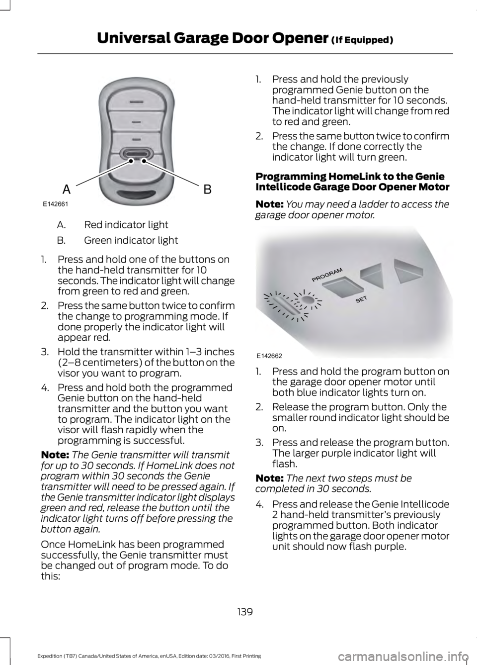
Red indicator lightA.
Green indicator lightB.
1. Press and hold one of the buttons onthe hand-held transmitter for 10seconds. The indicator light will changefrom green to red and green.
2.Press the same button twice to confirmthe change to programming mode. Ifdone properly the indicator light willappear red.
3. Hold the transmitter within 1–3 inches(2–8 centimeters) of the button on thevisor you want to program.
4. Press and hold both the programmedGenie button on the hand-heldtransmitter and the button you wantto program. The indicator light on thevisor will flash rapidly when theprogramming is successful.
Note:The Genie transmitter will transmitfor up to 30 seconds. If HomeLink does notprogram within 30 seconds the Genietransmitter will need to be pressed again. Ifthe Genie transmitter indicator light displaysgreen and red, release the button until theindicator light turns off before pressing thebutton again.
Once HomeLink has been programmedsuccessfully, the Genie transmitter mustbe changed out of program mode. To dothis:
1. Press and hold the previouslyprogrammed Genie button on thehand-held transmitter for 10 seconds.The indicator light will change from redto red and green.
2.Press the same button twice to confirmthe change. If done correctly theindicator light will turn green.
Programming HomeLink to the GenieIntellicode Garage Door Opener Motor
Note:You may need a ladder to access thegarage door opener motor.
1. Press and hold the program button onthe garage door opener motor untilboth blue indicator lights turn on.
2. Release the program button. Only thesmaller round indicator light should beon.
3.Press and release the program button.The larger purple indicator light willflash.
Note:The next two steps must becompleted in 30 seconds.
4.Press and release the Genie Intellicode2 hand-held transmitter’s previouslyprogrammed button. Both indicatorlights on the garage door opener motorunit should now flash purple.
139
Expedition (TB7) Canada/United States of America, enUSA, Edition date: 03/2016, First Printing
Universal Garage Door Opener (If Equipped)BAE142661 E142662
Page 143 of 500
5. Press and hold the previouslyprogrammed button on the visor for 2seconds. Repeat this step up to 3 timesuntil the garage door moves.
Programming is now complete.
Clearing a HomeLink Device
To erase programming from the threeHomeLink buttons press and hold the twoouter HomeLink buttons until the indicatorlight begins to flash. The indicator light willbegin flashing in 10 to 20 seconds, at whichtime both buttons should be released.Programming has now been erased, andthe indicator light should blink slowly toindicate the device is in train mode whenany of the three HomeLink buttons arepressed.
FCC and RSS-210 Industry CanadaCompliance
This device complies with Part 15 of theFCC Rules and with RSS-210 of IndustryCanada. Operation is subject to thefollowing two conditions: (1) this devicemay not cause harmful interference, and(2) this device must accept anyinterference received, includinginterference that may cause undesiredoperation.
Changes or modifications to your devicenot expressly approved by the partyresponsible for compliance can void theuser’s authority to operate the equipment.
140
Expedition (TB7) Canada/United States of America, enUSA, Edition date: 03/2016, First Printing
Universal Garage Door Opener (If Equipped)
Page 164 of 500
Automatic Transmission AdaptiveLearning
This feature may increase durability andprovide consistent shift feel over the lifeof your vehicle. A new vehicle ortransmission may have firm shifts, softshifts or both. This operation is considerednormal and will not affect function ordurability of the transmission. Over time,the adaptive learning process will fullyupdate transmission operation.
SelectShift™ AutomaticTransmission (If Equipped)
This feature gives you the ability to changegears up or down as desired.
As long as the engine speed does notexceed the maximum allowable limit youcan downshift. SelectShift automaticallydownshifts at low engine speeds in orderto prevent engine stalls.
Note:Engine damage may occur if youmaintain excessive engine revving withoutshifting.
SelectShift does not automatically upshift,even if the engine is approaching the RPMlimit, unless the accelerator pedal is at fulltravel. Take notice of the shift indicatorlamp, which alerts you when to shift tomake sure you achieve the highest level ofefficiency and fuel economy.
Press the + toggle switch on the sideof the gearshift lever to activateSelectShift.
•Press the (+) button to upshift.
•Press the (-) button to downshift.
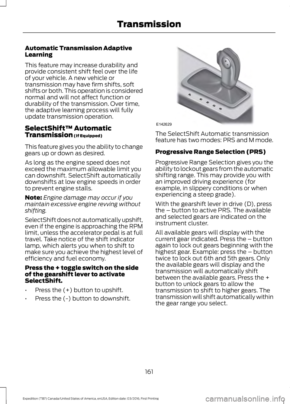
The SelectShift Automatic transmissionfeature has two modes: PRS and M mode.
Progressive Range Selection (PRS)
Progressive Range Selection gives you theability to lockout gears from the automaticshifting range. This may provide you withan improved driving experience (forexample, in slippery conditions or whenexperiencing a steep grade).
With the gearshift lever in drive (D), pressthe – button to active PRS. The availableand selected gears are indicated on theinstrument cluster.
All available gears will display with thecurrent gear indicated. Press the – buttonagain to lock out gears beginning with thehighest gear. Example: press the – buttontwice to lock out 6th and 5th gears. Onlythe available gears will display and thetransmission will automatically shiftbetween the available gears. Press the +button to unlock gears to allow thetransmission to shift to higher gears. Thetransmission will shift automatically withinthe gear range you select.
161
Expedition (TB7) Canada/United States of America, enUSA, Edition date: 03/2016, First Printing
TransmissionE142629
Page 170 of 500
3. Move the 4WD switch to the desiredmode.
The information display will display amessage indicating a 4X4 shift is inprogress. The information display will thendisplay the system mode selected.
If any of the above shift conditions are notmet, the shift will not occur and theinformation display will display informationguiding the driver through the proper rangeof shifting procedures.
If SHIFT DELAYED PULL FORWARD isdisplayed in the information display,transfer case gear tooth blockage ispresent. To alleviate this condition, placethe transmission in a forward gear, movethe vehicle forward approximately 5 ft(2 m), and shift the transmission back toneutral (N) to allow the transfer case tocomplete the range shift.
How Your Vehicle Differs FromOther Vehicles
WARNING
Vehicles with a higher center ofgravity such as utility and four-wheeldrive vehicles handle differently thanvehicles with a lower center of gravity.Utility and four-wheel drive vehicles arenot designed for cornering at speeds ashigh as passenger cars any more thanlow-slung sports cars are designed toperform satisfactorily under off-roadconditions. Avoid sharp turns, excessivespeed and abrupt maneuvers in thesevehicles. Failure to drive cautiously couldresult in an increased risk of loss of vehiclecontrol, vehicle rollover, personal injury anddeath.
Truck and utility vehicles can differ fromsome other vehicles. Your vehicle may behigher to allow it to travel over roughterrain without getting hung up ordamaging underbody components.
The differences that make your vehicle soversatile also make it handle differentlythan an ordinary passenger car.
Maintain steering wheel control at alltimes, especially in rough terrain. Sincesudden changes in terrain can result inabrupt steering wheel motion, make sureyou grip the steering wheel from theoutside. Do not grip the spokes.
Drive cautiously to avoid vehicle damagefrom concealed objects such as rocks andstumps.
You should either know the terrain orexamine maps of the area before driving.Map out your route before driving in thearea. To maintain steering and brakingcontrol of your vehicle, you must have allfour wheels on the ground and they mustbe rolling, not sliding or spinning.
Driving Off-Road With Truck andUtility Vehicles
Note:On some models, the initial shift fromtwo-wheel drive to four-wheel drive whileyour vehicle is moving can cause somemomentary clunk and ratcheting sounds.This is the front drivetrain coming up tospeed and the automatic locking hubsengaging and is not cause for concern.
Note:Your vehicle may be equipped witha front air dam that can become damaged(due to reduced ground clearance) whentaking your vehicle off-road. You mayremove this air dam by removing eight bolts.
Four-wheel drive vehicles are speciallyequipped for driving on sand, snow, mudand rough terrain and have operatingcharacteristics that are somewhatdifferent from conventional vehicles, bothon and off the road.
167
Expedition (TB7) Canada/United States of America, enUSA, Edition date: 03/2016, First Printing
Four-Wheel Drive (If Equipped)
Page 180 of 500

PRINCIPLE OF OPERATION
WARNINGS
Vehicle modifications involvingbraking system, aftermarket roofracks, suspension, steering system,tire construction and wheel and tire sizemay change the handling characteristicsof your vehicle and may adversely affectthe performance of the electronic stabilitycontrol system. In addition, installing anystereo loudspeakers may interfere withand adversely affect the electronic stabilitycontrol system. Install any aftermarketstereo loudspeaker as far as possible fromthe front center console, the tunnel, andthe front seats in order to minimize the riskof interfering with the electronic stabilitycontrol sensors. Reducing theeffectiveness of the electronic stabilitycontrol system could lead to an increasedrisk of loss of vehicle control, vehiclerollover, personal injury and death.
Remember that even advancedtechnology cannot defy the laws ofphysics. It’s always possible to losecontrol of a vehicle due to inappropriatedriver input for the conditions. Aggressivedriving on any road condition can causeyou to lose control of your vehicleincreasing the risk of personal injury orproperty damage. Activation of theelectronic stability control system is anindication that at least some of the tireshave exceeded their ability to grip the road;this could reduce the operator’s ability tocontrol the vehicle potentially resulting ina loss of vehicle control, vehicle rollover,personal injury and death. If your electronicstability control system activates, SLOWDOWN.
The system automatically turns on eachtime you switch the ignition on.
If a fault occurs in either the stabilitycontrol or the traction control system, youmay experience the following conditions:
•The stability and traction control lightilluminates steadily.
•The stability control and tractioncontrol systems do not enhance yourvehicle's ability to maintain traction ofthe wheels.
If a driving condition activates either thestability control or the traction controlsystem you may experience the followingconditions:
•The stability and traction control lightflashes.
•Your vehicle slows down.
•Reduced engine power.
•A vibration in the brake pedal.
•The brake pedal is stiffer than usual.
•If the driving condition is severe andyour foot is not on the brake, the brakepedal may move as the system applieshigher brake force.
The stability control system has severalfeatures built into it to help you maintaincontrol of your vehicle:
Electronic Stability Control
The system enhances your vehicle’s abilityto prevent skids or lateral slides byapplying brakes to one or more of thewheels individually and, if necessary,reducing engine power.
Roll Stability Control
The system enhances your vehicle’s abilityto prevent rollovers by detecting yourvehicle’s roll motion and the rate at whichit changes by applying the brakes to oneor more wheels individually.
177
Expedition (TB7) Canada/United States of America, enUSA, Edition date: 03/2016, First Printing
Stability Control
Page 214 of 500
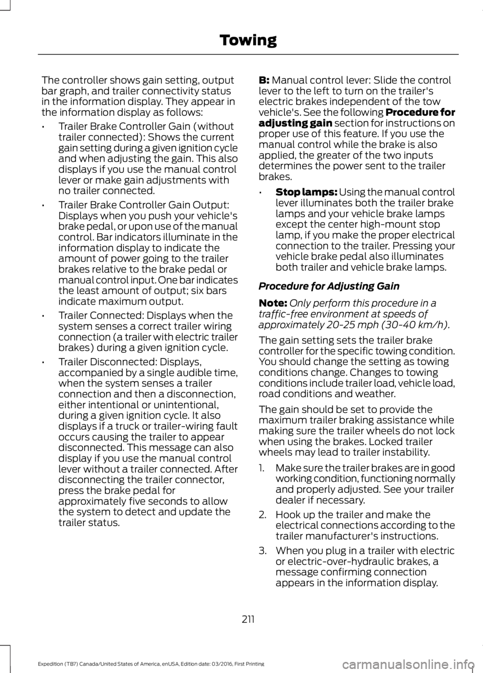
The controller shows gain setting, outputbar graph, and trailer connectivity statusin the information display. They appear inthe information display as follows:
•Trailer Brake Controller Gain (withouttrailer connected): Shows the currentgain setting during a given ignition cycleand when adjusting the gain. This alsodisplays if you use the manual controllever or make gain adjustments withno trailer connected.
•Trailer Brake Controller Gain Output:Displays when you push your vehicle'sbrake pedal, or upon use of the manualcontrol. Bar indicators illuminate in theinformation display to indicate theamount of power going to the trailerbrakes relative to the brake pedal ormanual control input. One bar indicatesthe least amount of output; six barsindicate maximum output.
•Trailer Connected: Displays when thesystem senses a correct trailer wiringconnection (a trailer with electric trailerbrakes) during a given ignition cycle.
•Trailer Disconnected: Displays,accompanied by a single audible time,when the system senses a trailerconnection and then a disconnection,either intentional or unintentional,during a given ignition cycle. It alsodisplays if a truck or trailer-wiring faultoccurs causing the trailer to appeardisconnected. This message can alsodisplay if you use the manual controllever without a trailer connected. Afterdisconnecting the trailer connector,press the brake pedal forapproximately five seconds to allowthe system to detect and update thetrailer status.
B: Manual control lever: Slide the controllever to the left to turn on the trailer'selectric brakes independent of the towvehicle's. See the following Procedure foradjusting gain section for instructions onproper use of this feature. If you use themanual control while the brake is alsoapplied, the greater of the two inputsdetermines the power sent to the trailerbrakes.
•Stop lamps: Using the manual controllever illuminates both the trailer brakelamps and your vehicle brake lampsexcept the center high-mount stoplamp, if you make the proper electricalconnection to the trailer. Pressing yourvehicle brake pedal also illuminatesboth trailer and vehicle brake lamps.
Procedure for Adjusting Gain
Note:Only perform this procedure in atraffic-free environment at speeds ofapproximately 20-25 mph (30-40 km/h).
The gain setting sets the trailer brakecontroller for the specific towing condition.You should change the setting as towingconditions change. Changes to towingconditions include trailer load, vehicle load,road conditions and weather.
The gain should be set to provide themaximum trailer braking assistance whilemaking sure the trailer wheels do not lockwhen using the brakes. Locked trailerwheels may lead to trailer instability.
1.Make sure the trailer brakes are in goodworking condition, functioning normallyand properly adjusted. See your trailerdealer if necessary.
2. Hook up the trailer and make theelectrical connections according to thetrailer manufacturer's instructions.
3. When you plug in a trailer with electricor electric-over-hydraulic brakes, amessage confirming connectionappears in the information display.
211
Expedition (TB7) Canada/United States of America, enUSA, Edition date: 03/2016, First Printing
Towing
Page 215 of 500
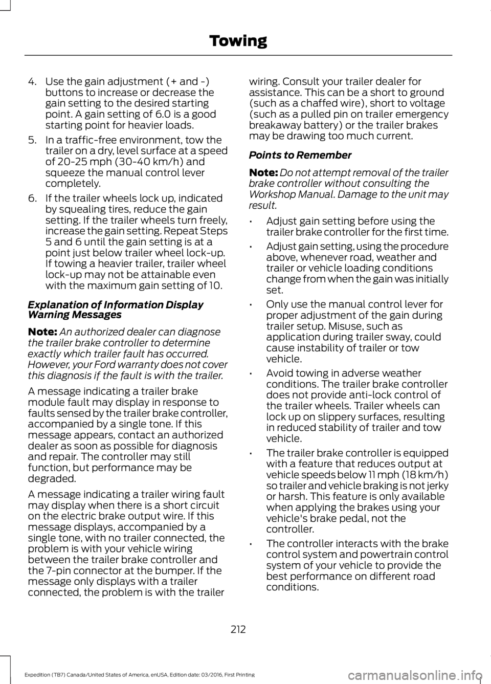
4. Use the gain adjustment (+ and -)buttons to increase or decrease thegain setting to the desired startingpoint. A gain setting of 6.0 is a goodstarting point for heavier loads.
5. In a traffic-free environment, tow thetrailer on a dry, level surface at a speedof 20-25 mph (30-40 km/h) andsqueeze the manual control levercompletely.
6. If the trailer wheels lock up, indicatedby squealing tires, reduce the gainsetting. If the trailer wheels turn freely,increase the gain setting. Repeat Steps5 and 6 until the gain setting is at apoint just below trailer wheel lock-up.If towing a heavier trailer, trailer wheellock-up may not be attainable evenwith the maximum gain setting of 10.
Explanation of Information DisplayWarning Messages
Note:An authorized dealer can diagnosethe trailer brake controller to determineexactly which trailer fault has occurred.However, your Ford warranty does not coverthis diagnosis if the fault is with the trailer.
A message indicating a trailer brakemodule fault may display in response tofaults sensed by the trailer brake controller,accompanied by a single tone. If thismessage appears, contact an authorizeddealer as soon as possible for diagnosisand repair. The controller may stillfunction, but performance may bedegraded.
A message indicating a trailer wiring faultmay display when there is a short circuiton the electric brake output wire. If thismessage displays, accompanied by asingle tone, with no trailer connected, theproblem is with your vehicle wiringbetween the trailer brake controller andthe 7-pin connector at the bumper. If themessage only displays with a trailerconnected, the problem is with the trailer
wiring. Consult your trailer dealer forassistance. This can be a short to ground(such as a chaffed wire), short to voltage(such as a pulled pin on trailer emergencybreakaway battery) or the trailer brakesmay be drawing too much current.
Points to Remember
Note:Do not attempt removal of the trailerbrake controller without consulting theWorkshop Manual. Damage to the unit mayresult.
•Adjust gain setting before using thetrailer brake controller for the first time.
•Adjust gain setting, using the procedureabove, whenever road, weather andtrailer or vehicle loading conditionschange from when the gain was initiallyset.
•Only use the manual control lever forproper adjustment of the gain duringtrailer setup. Misuse, such asapplication during trailer sway, couldcause instability of trailer or towvehicle.
•Avoid towing in adverse weatherconditions. The trailer brake controllerdoes not provide anti-lock control ofthe trailer wheels. Trailer wheels canlock up on slippery surfaces, resultingin reduced stability of trailer and towvehicle.
•The trailer brake controller is equippedwith a feature that reduces output atvehicle speeds below 11 mph (18 km/h)so trailer and vehicle braking is not jerkyor harsh. This feature is only availablewhen applying the brakes using yourvehicle's brake pedal, not thecontroller.
•The controller interacts with the brakecontrol system and powertrain controlsystem of your vehicle to provide thebest performance on different roadconditions.
212
Expedition (TB7) Canada/United States of America, enUSA, Edition date: 03/2016, First Printing
Towing
Page 217 of 500

•Allow more distance for stopping witha trailer attached. Anticipate stops andbrake gradually.
•Avoid parking on a grade. However, ifyou must park on a grade:
1. Turn the steering wheel to point yourvehicle tires away from traffic flow.
2. Set your vehicle parking brake.
3. Place the automatic transmission inposition P.
4. Place wheel chocks in front and backof the trailer wheels. (Chocks notincluded with vehicle.)
Your vehicle may be equipped with atemporary or conventional spare tire. A"temporary" spare tire is different in size(diameter or width), tread-type(All-Season or All Terrain) or is from adifferent manufacturer than the road tireson your vehicle. Consult information on thetire label or Safety Compliance label forlimitations when using.
Launching or Retrieving a Boat orPersonal Watercraft (PWC)
Note:Disconnect the wiring to the trailerbefore backing the trailer into the water.
Note:Reconnect the wiring to the trailerafter removing the trailer from the water.
When backing down a ramp during boatlaunching or retrieval:
•Do not allow the static water level torise above the bottom edge of the rearbumper.
•Do not allow waves to break higherthan 6 inches (15 centimeters) abovethe bottom edge of the rear bumper.
Exceeding these limits may allow water toenter vehicle components:
•Causing internal damage to thecomponents.
•Affecting driveability, emissions, andreliability.
Replace the rear axle lubricant anytimethe rear axle has been submerged in water.Water may have contaminated the rearaxle lubricant, which is not normallychecked or changed unless a leak issuspected or other axle repair is required.
TOWING POINTS (If Equipped)
WARNINGS
Using recovery hooks is dangerousand should only be done by a personfamiliar with proper vehicle recoverysafety practices. Improper use of recoveryhooks may cause hook failure or separationfrom the vehicle and could result in seriousinjury or death.
Always slowly remove the slack fromthe recovery strap prior to pulling.Failure to do so can introducesignificantly higher loads which can causethe recovery hooks to break off, or therecovery strap to fail which can causeserious injury or death.
Never link two straps together witha clevis pin. These heavy metalobjects could become projectiles ifthe strap breaks and can cause seriousinjury or death.
Your vehicle comes equipped withframe-mounted front recovery hooks.These hooks should never have a loadapplied to them greater than the grossvehicle weight rating of your vehicle.
214
Expedition (TB7) Canada/United States of America, enUSA, Edition date: 03/2016, First Printing
Towing