2017 FIAT TIPO 5DOORS STATION WAGON engine
[x] Cancel search: enginePage 29 of 264

Move the stalk upwards (unstable
position) to activate the MIST
function: operation is limited to the
time for which the stalk is held in this
position. When released, the stalk will
return to its default position and the
windscreen wiper will be stopped.
“Smart washing” function
Pull the stalk towards the steering
wheel (unstable position) to operate the
windscreen washer.
When the stalk is held pulled for longer
than half a second, the windscreen
wiper is moved with active control.
When the driver releases the stalk, the
windscreen wiper makes three strokes.
Afterwards, if the control is in position
, the washing cycle is concluded by
one last stroke after a 6 second pause.If the position isLOWorHIGH, the
smart washing function is not carried
out.
“Service Position” function
This function makes it possible to
replace the wipers or protect them in
conditions of ice and/or snow.
It can only be activated after stopping
the engine.
The "Service Position" function can be
explicitly requested within two minutes
of stopping the engine, when the
wipers have correctly returned to the
parking position.
The function can be activated by
turning the ring nut to position
and
moving the stalk upwards, to the MIST
position, more than three times. The
activations are used to position the
wipers as preferred. The function is
deactivated when the vehicle is turned
on, with a wiping request or when the
vehicle is moving (speed above
5 Km/h).
IMPORTANT Make sure, when starting
the engine, that the windscreen is free
of snow or ice before turning the
ignition key.RAIN SENSOR
(where provided)
7) 8)
This is a device located behind the
interior rear view mirrorfig. 37, in
contact with the windscreen and can
measure the amount of rain and,
consequently, manage the automatic
wiping mode of the windscreen in
accordance with the amount of water
on the screen (see the “Automatic
Wiping” paragraph).
REAR WINDOW WIPER /
WASHER
Ring nut 2, shown in fig. 38 can be set
to the following positions:
rear window wiper stopped
intermittent operation
continuous operation, without
pausing between two strokes.
36P2000061-000-000
3704146J0003EM
27
Page 30 of 264

The rear window wiper can be activated
in the following ways:
intermittent with a 2-second pause
between two strokes, when ring nut 2 is
in position
and the windscreen
wiper is not in operation;
synchronous (at half the windscreen
wiper frequency), when ring nut 2 is in
position
and the windscreen
wiper is in operation or when ring nut
2 is in position
, reverse gear is
engaged and the windscreen wiper is in
operation;
continuous when ring nut 2 is in
position
.
Push the stalk towards the dashboard
(rocking position) to activate the rear
window washer jet. Keep pushing the
lever to automatically activate both the
rear window washer jet and the rear
window wiper with a single movement.
Releasing the stalk will activate threestrokes, as described for the
windscreen wiper. If the position is
(rear window wiper stopped), after a
6 second pause, the washing cycle is
completed by a single stroke. The
smart wash cycle will not be performed
if the position is
.
WARNING
21)If the window needs to be cleaned,
make sure the device is deactivated or the
key is on STOP.
IMPORTANT
5)Never use the windscreen wipers to
remove layers of snow or ice from the
windscreen. In such conditions, the
windscreen wiper may be subjected to
excessive stress and the motor cut-out
switch, which prevents operation for a few
seconds, may intervene. If operation is not
subsequently restored, even after restarting
the engine, contact a Fiat Dealership.
6)Do not operate the windscreen wiper
with the blades lifted from the windscreen.
7)Do not activate the rain sensor when
washing the car in an automatic car wash.
8)Make sure the device is switched off if
there is ice on the windscreen.
38P2000062-000-000
28
KNOWING YOUR CAR
Page 34 of 264

1 - passenger compartment
temperature adjustment knob; the set
temperature is shown on the display;
2 - MAX A/C function on button;
3 - climate control compressor on/off
button;
4 - button for activating the MAX DEF
function (fast front window
defrosting/demisting);
5 - climate control system on/off
button;
6 - fan speed adjustment knob; the set
speed is shown on the display;
7 - air distribution selection buttons;
8 - heated rear window on/off button;
9 - internal air recirculation on/off
button;
10 - AUTO function activation button
(automatic operation).
Air distribution selection
By pressing the buttons//,it
is possible to set one of the 5 possible
air distributions manually:
Air flow to the windscreen and front
side window vents to
demist/defrost them.
Air flow at central and side
dashboard vents to ventilate the
chest and the face during the hot
season.
Air flow to the front and rear
footwell vents. This air distribution
setting heats the passenger
compartment most quickly, giving a
prompt sensation of warmth.
+Air flow distributed between
footwell vents (hotter air) and
central and side dashboard
vents (cooler air). This air
distribution setting is useful in
spring and autumn on sunny
days.
+Air flow distributed between
footwell vents and windscreen
and front side vents. This
distribution setting allows the
passenger compartment to be
warmed up efficiently and
prevents the windows from
misting up.
In AUTO mode, the climate control
system automatically manages air
distribution (the LEDs on buttons 7 are
off). When set manually, the air
distribution is indicated by the LEDs on
the selected buttons switching on.
In combined function mode the relevant
function is enabled simultaneously with
those already set by pressing the
corresponding button. If a button
whose function is already active is
pressed, the operation is cancelled and
the corresponding LED switches off. Torestore automatic control of the air
distribution after a manual selection,
press the AUTO button.
Start&Stop(where provided)
The automatic climate control system
manages the Start&Stop system
(engine off when vehicle speed is equal
to 0 km/h) to ensure adequate comfort
inside the vehicle.
When the Start&Stop system is on
(engine off and vehicle at a standstill),
the automatic recirculation
management is turned off always taking
air in from outside, to reduce the
probability of the windows misting up
(as the compressor is off).
IMPORTANT
2)The system uses a coolant that is
compatible with the laws in force in
countries where the vehicle is sold, R134a
or R1234yf. In case of a recharge
operation, only use the gas indicated on
the label placed in the engine
compartment. The use of other coolants
affects the efficiency and condition of the
system. The lubricant used for the
compressor is also strictly linked to the type
of cooling gas, please refer to a Fiat
Dealership.
32
KNOWING YOUR CAR
Page 36 of 264

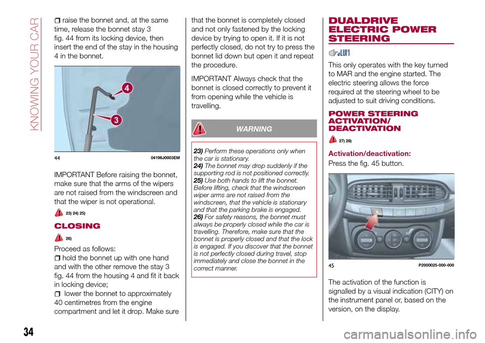
raise the bonnet and, at the same
time, release the bonnet stay 3
fig. 44 from its locking device, then
insert the end of the stay in the housing
4 in the bonnet.
IMPORTANT Before raising the bonnet,
make sure that the arms of the wipers
are not raised from the windscreen and
that the wiper is not operational.
23) 24) 25)
CLOSING
26)
Proceed as follows:
hold the bonnet up with one hand
and with the other remove the stay 3
fig. 44 from the housing 4 and fit it back
in locking device;
lower the bonnet to approximately
40 centimetres from the engine
compartment and let it drop. Make surethat the bonnet is completely closed
and not only fastened by the locking
device by trying to open it. If it is not
perfectly closed, do not try to press the
bonnet lid down but open it and repeat
the procedure.
IMPORTANT Always check that the
bonnet is closed correctly to prevent it
from opening while the vehicle is
travelling.
WARNING
23)Perform these operations only when
the car is stationary.
24)The bonnet may drop suddenly if the
supporting rod is not positioned correctly.
25)Use both hands to lift the bonnet.
Before lifting, check that the windscreen
wiper arms are not raised from the
windscreen, that the vehicle is stationary
and that the parking brake is engaged.
26)For safety reasons, the bonnet must
always be properly closed while the car is
travelling. Therefore, make sure that the
bonnet is properly closed and that the lock
is engaged. If you discover that the bonnet
is not perfectly closed during travel, stop
immediately and close the bonnet in the
correct manner.
DUALDRIVE
ELECTRIC POWER
STEERING
This only operates with the key turned
to MAR and the engine started. The
electric steering allows the force
required at the steering wheel to be
adjusted to suit driving conditions.
POWER STEERING
ACTIVATION/
DEACTIVATION
27) 28)
Activation/deactivation:
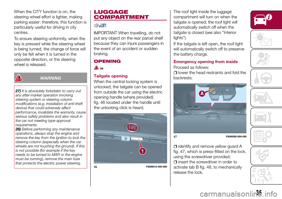
Press the fig. 45 button.
The activation of the function is
signalled by a visual indication (CITY) on
the instrument panel or, based on the
version, on the display.4404196J0003EM
45P2000025-000-000
34
KNOWING YOUR CAR
Page 37 of 264

When the CITY function is on, the
steering wheel effort is lighter, making
parking easier: therefore, this function is
particularly useful for driving in city
centres.
To ensure steering uniformity, when the
key is pressed while the steering wheel
is being turned, the change of force will
only be felt when it is turned in the
opposite direction, or the steering
wheel is released.
WARNING
27)It is absolutely forbidden to carry out
any after-market operation involving
steering system or steering column
modifications (e.g. installation of anti-theft
device) that could adversely affect
performance, invalidate the warranty, cause
serious safety problems and also result in
the car not meeting type-approval
requirements.
28)Before performing any maintenance
operations, always stop the engine and
remove the key from the ignition to lock the
steering column (especially when the car
wheels are not touching the ground). If this
is not possible (for example if the key
needs to be turned to MAR or the engine
must be running), remove the main fuse
that protects the electric power steering.
LUGGAGE
COMPARTMENT
IMPORTANT When travelling, do not
put any object on the rear parcel shelf
because they can injure passengers in
the event of an accident or sudden
braking.
OPENING
29)
Tailgate opening
When the central locking system is
unlocked, the tailgate can be opened
from outside the car using the electric
opening handle (where provided)
fig. 46 located under the handle until
the unlocking click is heard.The roof light inside the luggage
compartment will turn on when the
tailgate is opened; the roof light will
automatically switch off when the
tailgate is closed (see also "Interior
lights").
If the tailgate is left open, the roof light
will automatically switch off to preserve
the battery charge.
Emergency opening from inside
Proceed as follows:lower the head restraints and fold the
backrests;
identify and remove yellow guard A
fig. 47, which is press-fitted on the lock,
using the screwdriver provided;
insert the screwdriver in order to
activate tab B fig. 48, to mechanically
release the lock.46P2000015-000-000
47P2000092-000-000
35
Page 44 of 264

LPG MULTIPOINT
INJECTION SYSTEM
This product is produced by working
closely with qualified suppliers in the
LPG sector.
The injection system used on the car is
an efficient system in terms of engine
performance and is based on the
injection of LPG in a gaseous state.
In this system with four injectors, one
for each intake manifold, the fuel is
injected directly into the engine heat
transfer ducts, thereby metering the
LPG very precisely improving
combustion and, at the same time,
excluding any possibility of flame return.
By adapting the electronic control
technology of petrol engines to meet
LPG specifications, significant results in
terms of driveability and controlling
exhaust emissions have been obtained.
When running on LPG the engine has
almost the same torque and power
features as when running on petrol:
consequently, the car performance can
be compared.
SELECTION OF THE FUEL
SUPPLY TYPE
The car is configured for running
independently on either petrol or LPG.
The engine always starts up on petrol,
with automatic switching to LPG whenthe best conditions are achieved
(engine water temperature, minimum
engine rpm limit) for switching to LPG.
In addition, it is advisable to periodically
use up the petrol in the tank (until the
reserve warning light comes on) in order
to ensure that the petrol does not
become old and possibly deteriorate.
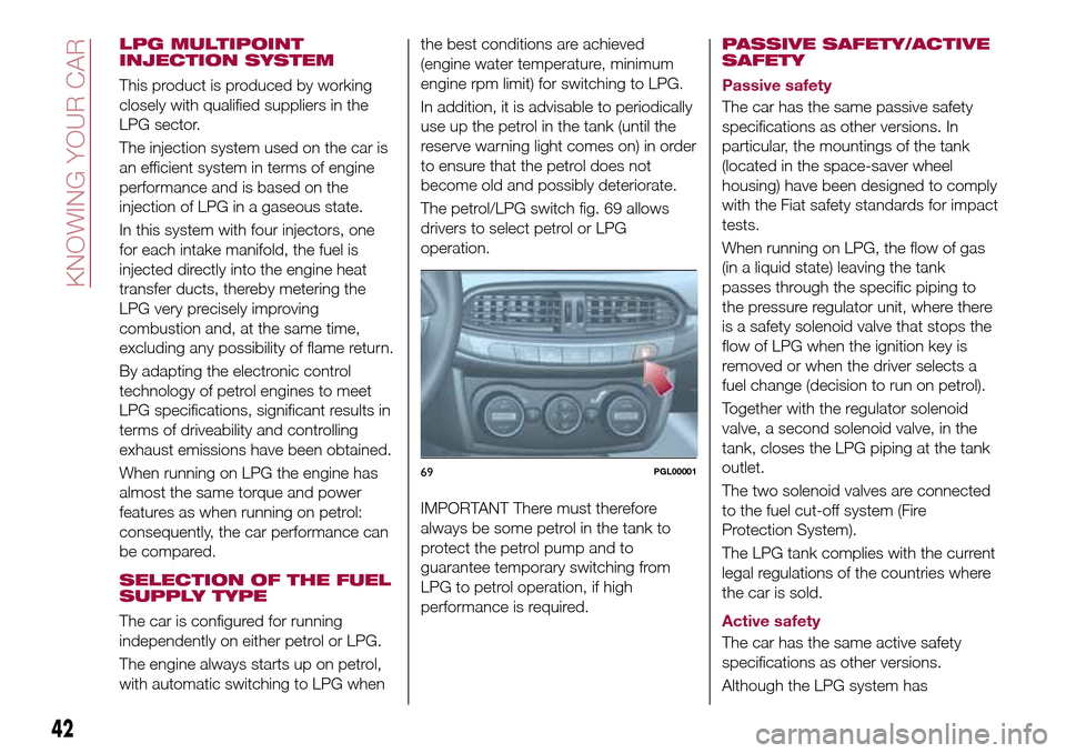
The petrol/LPG switch fig. 69 allows
drivers to select petrol or LPG
operation.
IMPORTANT There must therefore
always be some petrol in the tank to
protect the petrol pump and to
guarantee temporary switching from
LPG to petrol operation, if high
performance is required.PASSIVE SAFETY/ACTIVE
SAFETY
Passive safety
The car has the same passive safety
specifications as other versions. In
particular, the mountings of the tank
(located in the space-saver wheel
housing) have been designed to comply
with the Fiat safety standards for impact
tests.
When running on LPG, the flow of gas
(in a liquid state) leaving the tank
passes through the specific piping to
the pressure regulator unit, where there
is a safety solenoid valve that stops the
flow of LPG when the ignition key is
removed or when the driver selects a
fuel change (decision to run on petrol).
Together with the regulator solenoid
valve, a second solenoid valve, in the
tank, closes the LPG piping at the tank
outlet.
The two solenoid valves are connected
to the fuel cut-off system (Fire
Protection System).
The LPG tank complies with the current
legal regulations of the countries where
the car is sold.
Active safety
The car has the same active safety
specifications as other versions.
Although the LPG system has
69PGL00001
42
KNOWING YOUR CAR
Page 47 of 264

LPG TANK
The car has a pressurised tank for
storing LPG in a liquid state. It is
toroidal and is located in the spare
wheel compartment with suitable
protection.
LPG tank certification
The LPG tank is certified in accordance
with the regulations in force.
In Italy, the tank has a life of 10 years
starting from the car registration date. If
the vehicle has been registered in a
country other than Italy, the duration
and the testing/inspection procedures
of the LPG tank can vary depending on
the national provisions in force in that
country. In all case, when the time limit
for your country has expired, go to a
Fiat Dealer to have the tank replaced.
SOLENOID VALVES AND
SAFETY DEVICES
The system has a solenoid valve
located on the pressure reduction unit
and a solenoid valve fitted inside the
multivalve stack on the tank.
The main function of these solenoid
valves is to interrupt/allow the flow of
LPG to the supply circuit.
The solenoid valves are open when:
a request to run on LPG has been
made;
the optimum engine running
conditions are satisfied (engine coolant
temperature, minimum revs level) for
running on LPG;
there is enough LPG in the tank for
operation.
The multivalve stack fitted on the tank
includes:
a valve that automatically stops the
supply of LPG when the maximum
permitted filling level is reached (80% of
the total tank capacity);
a flow limiter which, if a piping is
broken, prevents the complete and
sudden escape of LPG;
a check valve preventing LPG
back-flow to the filler;
a safety solenoid valve on the LPG
supply line for enabling or preventing
the flow of gas towards the pressure
reducer;
a manual valve, positioned upstream
of the solenoid valve for bypassing the
LPG system for servicing operations;
a melting pad which, in the case of
overheating (temperature above
120°C), totally eliminates the danger of
excess pressure, releasing the LPG in
the tank to the outside as quickly as
possible in a controlled manner;
an analogue level gauge for LPG in
the tank.
PIPES
The piping for the LPG in a liquid state
(from the filler to the tank and from the
tank to the pressure regulator) is made
from copper coated in plastic.
The supply piping for the LPG in a
gaseous state (from the pressure
regulator to the LPG injectors) are made
from rubber.
REGULATION UNIT
The regulation unit (see the figure)
includes:
cut-out solenoid valve with gauze
filter;
pressure regulator.
The cut-out solenoid valveopens or
closes together with the solenoid valve
on the tank. It closes all LPG flow when
the engine is not running on gas. It also
acts as a safety device that prevents
73PLG00006
45
Page 48 of 264

the LPG flow if the fuel locking inertia
switch is activated.
the pressure regulatorallows the
LPG to pass from a liquid state to a
gaseous state through an expansion
chamber and maintains the pressure
required for the operation of the system
at a preset value.
LPG FILTER
The filter, located on the pressure
regulator outlet pipe fig. 74 filters the
gaseous LPG during the LPG injector
supply stage.
LPG INJECTORS
There are four injectors specifically for
LPG on a dedicated bracket on the
cylinder head and connected, via
specific pipes, to the individual intake
ducts fig. 75.
They are supplied with LPG in agaseous state at a constant pressure
and are controlled by a specific
electronic control unit.
A gas pressure and temperature sensor
that sends an appropriate electrical
signal in order to determine the LPG
injection time is fitted on the injectors.
ELECTRONIC CONTROL
UNIT
The car has a special electronic control
unit fig. 76, in the engine compartment,
controlling the LPG supply, using the
sensors located on the car.
The control unit for the injectors has the
same strategy as the petrol control unit
(timed sequential Multipoint).
LPG/PETROL SWITCH
This engine normally runs on LPG
except during starting when it runs on
petrol. Switching to LPG is automatic,
the warning light
1 fig. 77 on the
instrument panel, switches off.
If you specifically want to use petrol,
press the button on the dashboard
fig. 78. If the LED located above the
button turns on, it indicates that
74PGL00007
75PLG00008
76PLG00009
77PGL00022
46
KNOWING YOUR CAR