2017 FIAT TIPO 4DOORS wheel
[x] Cancel search: wheelPage 24 of 240

Deactivation
Keep the left stalk in main beam
headlights flashing position for a few
seconds or turn the key to MAR
position or wait until the period
previously set has ended.
MAIN BEAM HEADLIGHTS
With ring nut in position, push the
stalk forward toward the dashboard
(stable position). The
warning light
switches on in the instrument panel.
They are switched off by pulling the
stalk towards the steering wheel.
Flashing the headlights
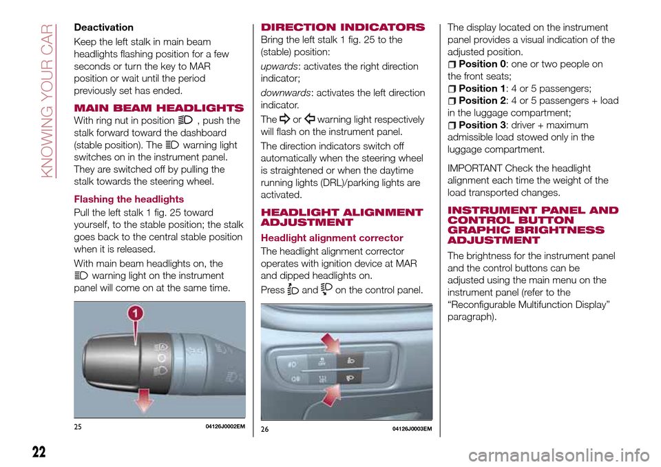
Pull the left stalk 1 fig. 25 toward
yourself, to the stable position; the stalk
goes back to the central stable position
when it is released.
With main beam headlights on, the
warning light on the instrument
panel will come on at the same time.
DIRECTION INDICATORS
Bring the left stalk 1 fig. 25 to the
(stable) position:
upwards: activates the right direction
indicator;
downwards: activates the left direction
indicator.
The
orwarning light respectively
will flash on the instrument panel.
The direction indicators switch off
automatically when the steering wheel
is straightened or when the daytime
running lights (DRL)/parking lights are
activated.
HEADLIGHT ALIGNMENT
ADJUSTMENT
Headlight alignment corrector
The headlight alignment corrector
operates with ignition device at MAR
and dipped headlights on.
Press
andon the control panel.The display located on the instrument
panel provides a visual indication of the
adjusted position.
Position 0: one or two people on
the front seats;
Position 1: 4 or 5 passengers;
Position 2: 4 or 5 passengers + load
in the luggage compartment;
Position 3: driver + maximum
admissible load stowed only in the
luggage compartment.
IMPORTANT Check the headlight
alignment each time the weight of the
load transported changes.
INSTRUMENT PANEL AND
CONTROL BUTTON
GRAPHIC BRIGHTNESS
ADJUSTMENT
The brightness for the instrument panel
and the control buttons can be
adjusted using the main menu on the
instrument panel (refer to the
“Reconfigurable Multifunction Display”
paragraph).
2504126J0002EM2604126J0003EM
22
KNOWING YOUR CAR
Page 26 of 240

WINDSCREEN
WASHER / WIPER
Operation is only possible with the
ignition device at MAR.
WINDSCREEN WIPER /
WASHER
Operation
22)
5) 6)
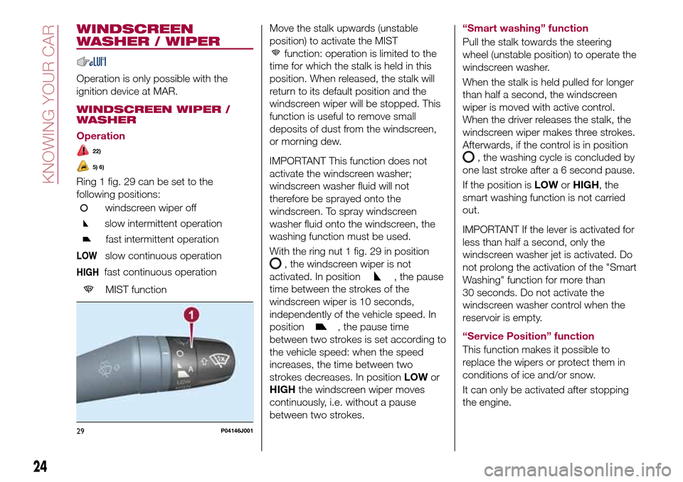
Ring 1 fig. 29 can be set to the
following positions:
windscreen wiper off
slow intermittent operation
fast intermittent operation
LOWslow continuous operation
HIGHfast continuous operation
MIST function
Move the stalk upwards (unstable
position) to activate the MIST
function: operation is limited to the
time for which the stalk is held in this
position. When released, the stalk will
return to its default position and the
windscreen wiper will be stopped. This
function is useful to remove small
deposits of dust from the windscreen,
or morning dew.
IMPORTANT This function does not
activate the windscreen washer;
windscreen washer fluid will not
therefore be sprayed onto the
windscreen. To spray windscreen
washer fluid onto the windscreen, the
washing function must be used.
With the ring nut 1 fig. 29 in position
, the windscreen wiper is not
activated. In position
, the pause
time between the strokes of the
windscreen wiper is 10 seconds,
independently of the vehicle speed. In
position
, the pause time
between two strokes is set according to
the vehicle speed: when the speed
increases, the time between two
strokes decreases. In positionLOWor
HIGHthe windscreen wiper moves
continuously, i.e. without a pause
between two strokes.“Smart washing” function
Pull the stalk towards the steering
wheel (unstable position) to operate the
windscreen washer.
When the stalk is held pulled for longer
than half a second, the windscreen
wiper is moved with active control.
When the driver releases the stalk, the
windscreen wiper makes three strokes.
Afterwards, if the control is in position
, the washing cycle is concluded by
one last stroke after a 6 second pause.
If the position isLOWorHIGH, the
smart washing function is not carried
out.
IMPORTANT If the lever is activated for
less than half a second, only the
windscreen washer jet is activated. Do
not prolong the activation of the "Smart
Washing" function for more than
30 seconds. Do not activate the
windscreen washer control when the
reservoir is empty.
“Service Position” function
This function makes it possible to
replace the wipers or protect them in
conditions of ice and/or snow.
It can only be activated after stopping
the engine.
29P04146J001
24
KNOWING YOUR CAR
Page 28 of 240

CLIMATE CONTROL
SYSTEM
1)
PASSENGER
COMPARTMENT AIR
DIFFUSERS
Adjustable air diffusers
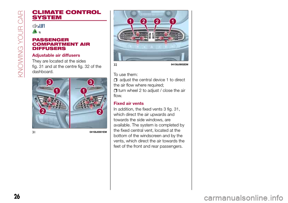
They are located at the sides
fig. 31 and at the centre fig. 32 of the
dashboard.
To use them:
adjust the central device 1 to direct
the air flow where required;
turn wheel 2 to adjust / close the air
flow.
Fixed air vents
In addition, the fixed vents 3 fig. 31,
which direct the air upwards and
towards the side windows, are
available. The system is completed by
the fixed central vent, located at the
bottom of the windscreen and by the
vents, which direct the air towards the
feet of the front and rear passengers.
3104156J0001EM
3204156J0002EM
26
KNOWING YOUR CAR
Page 35 of 240

Make sure that the bonnet is
completely closed and not only
fastened by the locking device by trying
to open it. If it is not perfectly closed,
do not try to press the bonnet lid down
but open it and repeat the procedure.
IMPORTANT Always check that the
bonnet is closed correctly to prevent it
from opening while the vehicle is
travelling.
WARNING
24)Perform these operations only when
the car is stationary.
25)The bonnet may drop suddenly if the
supporting rod is not positioned correctly.
26)Use both hands to lift the bonnet.
Before lifting, check that the windscreen
wiper arms are not raised from the
windscreen, that the vehicle is stationary
and that the parking brake is engaged.
27)For safety reasons, the bonnet must
always be properly closed while the car is
travelling. Therefore, make sure that the
bonnet is properly closed and that the lock
is engaged. If you discover that the bonnet
is not perfectly closed during travel, stop
immediately and close the bonnet in the
correct manner.
DUALDRIVE
ELECTRIC POWER
STEERING
This only operates with the key turned
to MAR and the engine started. The
electric steering allows the force
required at the steering wheel to be
adjusted to suit driving conditions.
IMPORTANT When turning the ignition
key quickly, full power steering
functionality can be achieved after a
few seconds.
IMPORTANT During parking
manoeuvres requiring a lot of steering,
the steering may become harder; this is
normal and is due to the intervention of
the system to protect the electric
steering motor from overheating. No
repair intervention is needed in this
case. When the car is used again, the
power steering will work normally again.
IMPORTANT The Dualdrive electric
power steering provides an electronic
damping effect when approaching the
end of travel. In some manoeuvring
conditions, the steering wheel may
perform an additional small rotation until
reaching its mechanical stop. This
behaviour is normal and is intended to
prevent excessive impacts with the
mechanical components located inside
the device.POWER STEERING
ACTIVATION/
DEACTIVATION
28) 29)
Engagement/disengagement
Press the fig. 42 button.
The activation of the function is
signalled by a visual indication (CITY) on
the instrument panel or, based on the
version, on the display.
When the CITY function is on, the
steering wheel effort is lighter, making
parking easier: therefore, this function is
particularly useful for driving in city
centres.
4204226J0001EM
33
Page 36 of 240

WARNING
28)It is absolutely forbidden to carry out
any after-market operation involving
steering system or steering column
modifications (e.g. installation of anti-theft
device) that could adversely affect
performance, invalidate the warranty, cause
serious safety problems and also result in
the car not meeting type-approval
requirements.
29)Before performing any maintenance
operations, always turn off the engine and
remove the key from the ignition to lock the
steering column (especially when the car
wheels are not touching the ground). If this
is not possible (for example if the key
needs to be turned to MAR or the engine
must be running), remove the main fuse
that protects the electric power steering.
BOOT
9)
IMPORTANT When travelling, do not
put any object on the rear parcel shelf
because they can injure passengers in
the event of an accident or sudden
braking.
OPENING
30)
Rear flap opening
When the central locking system is
unlocked, the rear boot flap can be
opened from outside the car using the
electric opening handle (where
provided) fig. 44 located under the
handle until the unlocking click is heard
or by pressing the
fig. 43 button on
the dashboard.The roof light inside the luggage
compartment will turn on when the rear
flap is opened; the roof light will
automatically switch off when the rear
flap is closed (see also "Interior lights").
If the rear flap is left open, the roof light
will automatically switch off to preserve
the battery charge.
4304206J0011EM
4404206J0001EM
34
KNOWING YOUR CAR
Page 38 of 240

VERSION WITH LPG
SYSTEM
(where provided)
31) 32)
10) 11) 12) 13)
INTRODUCTION
The LPG version features two fuel
supply systems: one for petrol and one
for LPG.
SELECTION OF THE FUEL
SUPPLY TYPE
The car is configured for running
independently on either petrol or LPG.
The engine always starts up on petrol,
with automatic switching to LPG when
the best conditions are achieved
(engine water temperature, minimum
engine rpm limit) for switching to LPG.
In addition, it is advisable to periodically
use up the petrol in the tank (until the
reserve warning light comes on) in order
to ensure that the petrol does not
become old and possibly deteriorate.
The petrol/LPG switch fig. 47 allows
drivers to select petrol or LPG
operation.
IMPORTANT There must therefore
always be some petrol in the tank to
protect the petrol pump and to
guarantee temporary switching from
LPG to petrol operation, if high
performance is required.
PASSIVE SAFETY/ACTIVE
SAFETY
Passive safety
The car has the same passive safety
specifications as other versions. In
particular, the mountings of the tank
(located in the space-saver wheel
housing) have been designed to comply
with the Fiat safety standards for impact
tests.When running on LPG, the flow of gas
(in a liquid state) leaving the tank
passes through the specific piping to
the pressure regulator unit, where there
is a safety solenoid valve that stops the
flow of LPG when the ignition key is
removed or when the driver selects a
fuel change (decision to run on petrol).
Together with the regulator solenoid
valve, a second solenoid valve, in the
tank, closes the LPG piping at the tank
outlet.
The two solenoid valves are connected
to the fuel cut-off system (Fire
Protection System).
The LPG tank complies with the current
legal regulations of the countries where
the car is sold.
47PGL6J0032
36
KNOWING YOUR CAR
Page 40 of 240

LPG TANK
The car has a pressurised tank for
storing LPG in a liquid state. It is
toroidal and is located in the spare
wheel compartment with suitable
protection.
LPG tank certification
The LPG tank is certified in accordance
with the regulations in force.
In Italy, the tank has a life of 10 years
starting from the car registration date. If
the vehicle has been registered in a
country other than Italy, the duration
and the testing/inspection procedures
of the LPG tank can vary depending on
the national provisions in force in that
country. In all case, when the time limit
for your country has expired, go to a
Fiat Dealer to have the tank replaced.
LPG/PETROL SWITCH
This engine normally runs on LPG
except during starting when it runs on
petrol. Switching to LPG is automatic,
the warning light
1 fig. 50 on the
instrument panel, switches off.If you specifically want to use petrol,
press the button on the dashboard
fig. 51. If the LED located above the
button turns on, it indicates that
switching has taken place correctly.
Regardless of the last fuel system used,
at the following engine starting, after the
initial petrol stage, the system will
automatically switch to LPG.The bars 2 fig. 52 on the display
indicate the level of LPG in the tank.
To guarantee switching in full safety, the
actual change to the chosen fuel
system takes place depending on the
car usage conditions; it may not
therefore be immediate. Switching is
confirmed by the switching on/off of the
green warning light
on the
instrument panel.
When switching is requested, metallic
noise from the valves which pressurise
the circuit can be heard. For the
switching logic described above, a
delay between the valve ticking and the
switching off of the instrument panel
indication is completely normal.
50PGL00022
51PGL6J0032
52PGL00023
38
KNOWING YOUR CAR
Page 49 of 240

DISPLAY
DESCRIPTION
The vehicle is equipped with a display
that can show useful information to the
driver while driving.
GEAR SHIFT INDICATOR
The Gear Shift Indicator (GSI) system
advises the driver to change gear
through a special indication on the
display.
Through the GSI, the driver is informed
that the gear change will allow a
reduction in fuel consumption.
When the
icon appears on the
display, the GSI suggests switching to a
higher gear, while when the
icon is
displayed, the GSI suggests changing
to a lower gear.
The indication in the display remains
until a gear is shifted or the driving
conditions go back to a situation where
gearshifting is not required to improve
consumption.
MULTIFUNCTION
DISPLAY
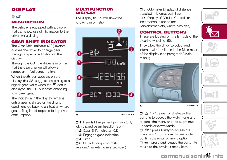
The display fig. 59 will show the
following information:
1: Headlight alignment position (only
with dipped beam headlights on)
2: Gear Shift Indicator (GSI)
3: Engaged gear indication
4: Time
5: Outside temperature (for
versions/markets, where provided)
6: Odometer (display of distance
travelled in kilometres/miles)
7: Display of "Cruise Control" or
instantaneous speed (for
versions/markets, where provided)
CONTROL BUTTONS
These are located on the left side of the
steering wheel fig. 60.
They allow the driver to select and
interact with the items in the Main menu
of the display (see paragraph "Main
menu").
/: press and release the
buttons to access the Main menu and
to scroll the menu and the submenus
upwards or downwards.
: press briefly to access the
menu and/or go to next screen or to
confirm the required menu option.
: press and release the button to
return to the previous menu item.
5905036J0001EM
6005036J0002EM
47