Page 147 of 296
Light bulbs
Light bulbs Type Power Figure ref.
Main beam headlights H7 55W D
Dipped beam headlights H7 55W D
Front side lights / daytime running lights
W21/5W - LED
(#)--
Front fog lights
(*)H11 55W -
Front direction indicators WY21W 21W B
Side turn lightW16WF
(**) / WY5W
(***)16W(**) / 5W (***)A
Rear direction indicators PY2IW 21W B
Side lights W5W 5W A
Rear side lights P21/5W 21/5W B
Rear side lights/Brake lights P21W 21W B
Third brake light W5W 5W B
Reverse gear W16W 16W B
Rear fog light W16W 16W B
Number plate C5W 5W A
Front roof light (movable lens) 12V10W 10W C
Rear ceiling light 12V10W 10W C
(#) where provided, instead of bulb W21/5W
(*)for versions/markets, where provided
(**)XL and Tempo Libero versions
(***)all other versions
145
Page 150 of 296

Side
To change the bulbs, proceed as
follows fig. 134:
move the mirror manually to permit
access to the two fixing screws A;
using the Phillips screwdriver
provided, undo the screws and extract
the bulb holder assembly, releasing it
from the teeth;
undo the bulb and replace bulb B,
turning it anticlockwise.FOG LIGHTS
(for versions/markets, where provided)
To replace the front fog light bulbs,
proceed as follows:
steer the wheel completely inwards;
undo the screw A and remove the
flap B fig. 135;
release the clip C fig. 136 and
disconnect the electrical connector D;
turn and remove the bulb holder E;
release the bulb and replace it;
refit the new bulb and carry out the
procedure described previously in
reverse.REAR LIGHT CLUSTERS
The bulbs are arranged inside the light
cluster as follows fig. 137:
A brake/side lights
B side light
C direction indicators
D reverse lights.
E rear fog lights
To replace the bulb, proceed as follows
fig. 138, fig. 139:
open the rear wing door.
133F1A0317
134F1A0195
135F1A0361
136F1A0362
137F1A0318
148
IN AN EMERGENCY
Page 151 of 296
undo the 7 fixing screws A of the
plastic cover;
undo the two fixing screws B;
extract the unit outwards and
disconnect the electrical connector;
unscrew the screws C using the
screwdriver provided and remove the
bulb holder;
remove the bulb D, E, F pushing it
gently and turning it anticlockwise
(“bayonet” locking), then replace it;
remove the bulb G, H pulling outwards;
refit the bulb holder and tighten the
screws C;
reconnect the electrical connector,
correctly reposition the unit on the body
of the vehicle and then tighten the
fixing screws B;
refit the plastic cover fastening it
with the 7 fixing screws A.For truck and chassis cab versions:
Undo the four screws H fig. 140 and
replace the bulbs:
I bulb for rear fog light
L bulb for reversing light
M bulb for side light
N bulb for brake light
O bulb for side light.
138F1A0319139F1A0320
140F1A0200
149
Page 152 of 296

THIRD BRAKE LIGHTS
To replace the bulb proceed as follows:
undo the two fixing screws A fig.
141;
extract the lens unit;
press the tabs B fig. 142 together
and remove the bulb holder;
remove the snap-fitted bulb and
replace.NUMBER PLATE LIGHTS
To replace the bulb proceed as follows:
operate in the point indicated by
the arrow and remove the lens unit A
fig. 143;
change the bulb releasing it from the
side contacts and making sure the
new bulb is correctly fastened between
the contacts;
refit the snap-fitted lens unit.
SIDE LIGHTS
(for versions/markets, where provided)
To replace the bulb proceed as follows:
for extra-long van:
– undo the two fixing screws C fig. 144
and remove the headlight;
– remove the bulb holder D on the rear
of the light cluster, turning it through
a 1/4 turn;
– remove the snap-fitted bulb and
replace.
for chassis cabs with platform:
– remove the bulb-holder on the rear of
the light cluster, turning through 1/4
turn;
– remove the snap-fitted bulb and
replace.141F1A0204
142F1A0205
143F1A0206
144F1A0207
150
IN AN EMERGENCY
Page 157 of 296

Dashboard fusebox
Protected device Fuse Ampere
Right dipped beam headlight F12 7.5
Left dipped headlight F13 7.5
Engine compartment control unit relay, dashboard control unit relay
(+key)F31 5
Lighting of roof lights in the passenger compartment (+battery) F32 7.5
Battery monitoring sensor for Start&Stop versions (+battery) F33 7.5
Minibus interior lights (emergency) F34 7.5
Radio, Climate control system, Alarm, Tachograph, Battery
disconnecting control unit, Timer Webasto timer (+battery), TPMS,
Current stabiliser for radio setup (S&S)F36 10
Brake lights control (main), Instrument panel (+key), Gateway (for
transformers)F37 7.5
Door lock (+battery) F38 20
Windscreen wiper (+key) F43 20
Driver's side electric window F47 20
Passenger side electric window F48 20
Parking sensor control unit, radio, steering wheel controls, central
control panel, left control panel, auxiliary panel, battery
disconnecting control unit (+key), Trailer hook, Rain sensor, Current
stabiliser (for S&S)F49 5
155
Page 166 of 296
WARNING
141)Never replace a fuse with another with a higher amp rating; RISK OF FIRE. If a general protection fuse (MEGA-FUSE, MIDI-FUSE) is
activated, contact a Fiat Dealership.
142)Before replacing a fuse, make sure that the ignition key has been removed and that all the other services are switched off and/or
disengaged.
143)If the replaced fuse blows again, contact a Fiat Dealership.
144)Contact Fiat Dealership if a safety system (airbags, brakes), engine system (engine, gearbox) or steering system general protection fuse
blows.
WARNING
47)Never replace a faulty fuse with metal wires or anything else.
164
IN AN EMERGENCY
Page 168 of 296

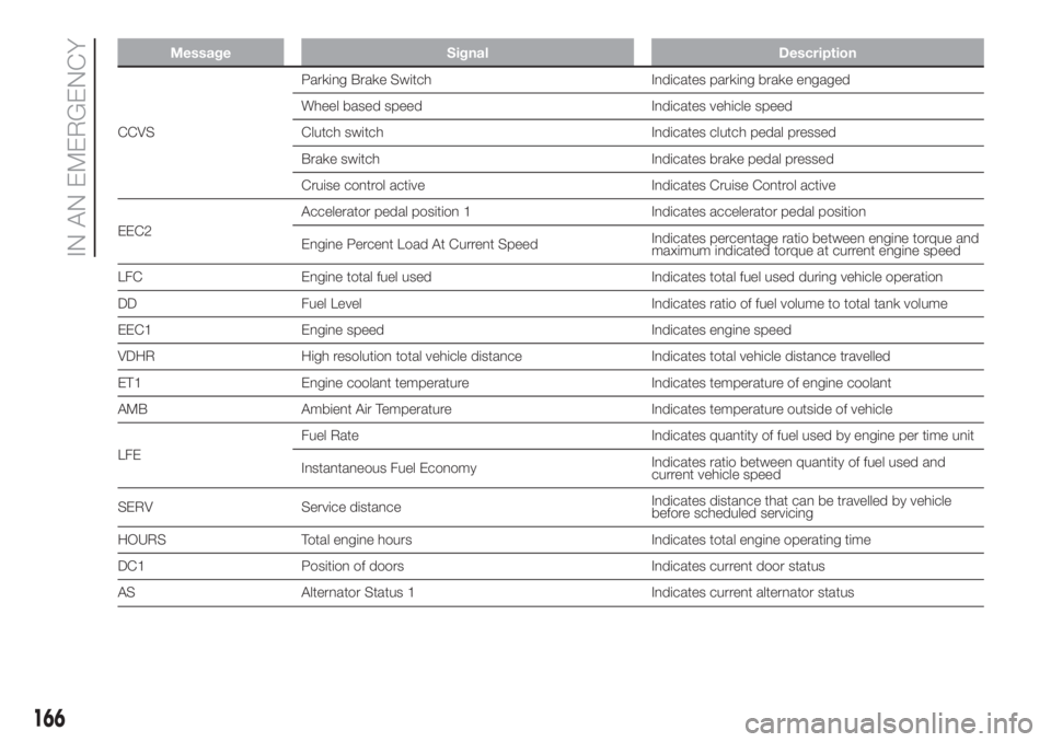
Message Signal Description
CCVSParking Brake Switch Indicates parking brake engaged
Wheel based speed Indicates vehicle speed
Clutch switch Indicates clutch pedal pressed
Brake switch Indicates brake pedal pressed
Cruise control active Indicates Cruise Control active
EEC2Accelerator pedal position 1 Indicates accelerator pedal position
Engine Percent Load At Current SpeedIndicates percentage ratio between engine torque and
maximum indicated torque at current engine speed
LFC Engine total fuel used Indicates total fuel used during vehicle operation
DD Fuel Level Indicates ratio of fuel volume to total tank volume
EEC1 Engine speed Indicates engine speed
VDHR High resolution total vehicle distance Indicates total vehicle distance travelled
ET1 Engine coolant temperature Indicates temperature of engine coolant
AMB Ambient Air Temperature Indicates temperature outside of vehicle
LFEFuel Rate Indicates quantity of fuel used by engine per time unit
Instantaneous Fuel EconomyIndicates ratio between quantity of fuel used and
current vehicle speed
SERV Service distanceIndicates distance that can be travelled by vehicle
before scheduled servicing
HOURS Total engine hours Indicates total engine operating time
DC1 Position of doors Indicates current door status
AS Alternator Status 1 Indicates current alternator status
166
IN AN EMERGENCY
Page 170 of 296

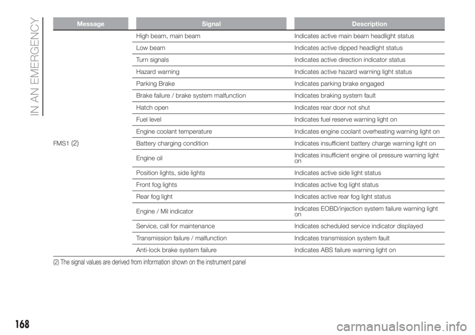
Message Signal Description
FMS1(2)
High beam, main beam Indicates active main beam headlight status
Low beam Indicates active dipped headlight status
Turn signals Indicates active direction indicator status
Hazard warning Indicates active hazard warning light status
Parking Brake Indicates parking brake engaged
Brake failure / brake system malfunction Indicates braking system fault
Hatch open Indicates rear door not shut
Fuel level Indicates fuel reserve warning light on
Engine coolant temperature Indicates engine coolant overheating warning light on
Battery charging condition Indicates insufficient battery charge warning light on
Engine oilIndicates insufficient engine oil pressure warning light
on
Position lights, side lights Indicates active side light status
Front fog lights Indicates active fog light status
Rear fog light Indicates active rear fog light status
Engine / Mil indicatorIndicates EOBD/injection system failure warning light
on
Service, call for maintenance Indicates scheduled service indicator displayed
Transmission failure / malfunction Indicates transmission system fault
Anti-lock brake system failure Indicates ABS failure warning light on
(2) The signal values are derived from information shown on the instrument panel
168
IN AN EMERGENCY