2017 FIAT 500X mirror
[x] Cancel search: mirrorPage 79 of 284

"Blind Spot Assist", "Visual" mode
When this mode is active, the BSA
system sends a visual warning to the
door mirror relating to the object
detected.
However, when operating in RCP
mode, the system sends visual and
acoustic warnings when the presence
of an object is detected.
When an acoustic warning is sent, the
Uconnect™volume is lowered.
"Blind Spot Assist", "Visual and
acoustic" mode
When this mode is active, the BSA
system sends a visual warning to the
door mirror relating to the object
detected.
If the direction indicator on the side
where an obstacle has been detected is
activated, an acoustic warning is
emitted as well.
When a direction indicator is active and
an object is simultaneously detected on
the same side, both the acoustic and
visual warnings are emitted. The
Uconnect™volume is also lowered.
During "RCP" operating mode, the
system sends acoustic and visual
warnings if the presence of an object is
detected. When an acoustic warning is
sent, theUconnect™volume is also
lowered."Blind Spot Assist" function
deactivation
When the system is deactivated ("Blind
spot alert" mode at "OFF"), the BSA or
RCP systems will not emit neither
acoustic nor visual warnings.
The BSA system will store the operating
mode running when the engine was
switched off. Each time the engine is
started, the operating mode stored
previously will be recalled and used.
IMPORTANT The system is an aid for
vehicle driving, it DOES NOT warn the
driver about incoming vehicles outside
of the detection areas. The driver must
always maintain a sufficient level of
attention to the traffic and road
conditions and for controlling the
trajectory of the vehicle.
FULL BRAKE CONTROL
SYSTEM
58) 59) 60) 61)
21) 22) 23) 24) 25) 26) 27) 28) 29)
The vehicle can be equipped with the
"Full Brake Control" system. This is a
driving assistance system which
comprises a radar located behind the
front bumper fig. 59 and a camera
located in the central part of the
windscreen fig. 60.In the event of an imminent collision the
system intervenes by automatically
braking the vehicle to prevent the crash
or reduce its effects.
The system provides the driver with
acoustic and visual signals through
specific messages on the instrument
panel display.
The system may lightly brake to warn
the driver if a possible frontal accident is
59F1B0095C
60F1B0096C
77
Page 113 of 284

STARTING THE
ENGINE
Before starting the engine, adjust the
seat, the interior rear view mirrors, the
door mirrors and fasten the seat belt
correctly.
Never press the accelerator pedal for
starting the engine.
If necessary, messages indicating the
starting procedure can be shown on
the display.
ENGINE STARTING
PROCEDURE
103) 104) 105) 106)
31) 32) 33) 34)
Versions with manual gearbox
Proceed as follows:
engage the electric parking brake
and place the gear lever in neutral;
bring the ignition device to MAR. On
Diesel versions, warning light
lights
up in the instrument panel: wait for the
warning light to switch off;
fully depress the clutch pedal
without touching the accelerator;
turn the ignition device to AVV and
release it as soon as the engine starts;
if the engine does not start within
10 seconds, bring the ignition deviceback to STOP and wait for
10-15 seconds before repeating the
starting procedure.
after the manoeuvre has been
repeated, if the problem persists,
contact a Fiat Dealership.
Versions with automatic
transmission
Proceed as follows:
engage the electric parking brake
and set the gear lever to P (Park) or N
(Neutral);
fully depress the brake pedal without
touching the accelerator;
set the ignition device to AVV;
if the engine does not start, bring
the ignition device back to STOP and
wait for 10-15 seconds before
repeating the starting procedure;
after the manoeuvre has been
repeated, if the problem persists,
contact a Fiat Dealership.
ENGINE STARTING
FAILURE
Starting the engine with electronic
key battery (Keyless Go) run down
or flat
If the ignition device does not respond
when the relevant button is pressed the
electronic key battery might be run
down or flat. Therefore, the system
does not detect the presence of the
electronic key on board the vehicle anddisplays a dedicated message. In this
case, rest the rounded edge of the
electronic key (the side opposite the
metal insert) on the ignition device and
press the button using the electronic
key. The ignition device is thus activated
and the engine can be started.
WARNING
103)Do not try to start the engine pouring
fuel or other flammable fluid inside the
throttle body air intake: this might damage
the engine and injury people nearby.
104)It is dangerous to run the engine in
enclosed areas. The engine takes in
oxygen and releases carbon dioxide,
carbon monoxide and other toxic gases.
105)The brake servo is not active until the
engine is started, so you would need to
apply much more force than usual to the
brake pedal.
106)Do not start the engine by pushing,
towing or driving downhill. These
manoeuvres may damage the catalytic
converter.
IMPORTANT
31)We recommend that during the initial
period, or during the first 1600 km, you do
not drive to full car performance (e.g.
excessive acceleration, long journeys at top
speed, sharp braking, etc.).
111
Page 137 of 284

a suitable distance is kept from the
vehicle in front;
the direction indicator (for leaving the
lane) is not active;
the lane limit lines are perfectly
visible on both sides (for activation of
the tactile warning only).
NOTE The system does not apply the
vibration to the steering wheel every
time a safety system is activated
(brakes, ABS, ASR system, ESC
system, Full Brake Control system,
etc.).
IMPORTANT
57)Projecting loads on the roof of the
vehicle may interfere with the correct
operation of the camera. Before starting
make sure the load is correctly positioned,
in order not to cover the camera operating
range.
58)If the windscreen must be replaced due
to scratches, chipping or breakage, contact
exclusively a Fiat Dealership. Do not
replace the windscreen on your own, risk of
malfunction! It is advisable to replace the
windscreen if it is damaged in the area of
the camera.
59)Do not tamper with nor operate on the
camera. Do not close the openings in the
aesthetic cover located under the interior
rear view mirror. In the event of a failure of
the camera, contact a Fiat Dealership.60)Do not cover the operating range of the
camera with stickers or other objects. Also
pay attention to other objects on the
bonnet (e.g. a layer of snow) and make
sure they do not interfere with the camera.
61)The camera may have limited or absent
operation due to weather conditions such
as: heavy rain, hail, thick fog, heavy snow,
formation of ice layers on the windscreen.
62)Camera operation may also be
compromised by the presence of dust,
condensation, dirt or ice on the
windscreen, by traffic conditions (e.g.
vehicles that are driving not aligned with
yours, vehicle driving in a transverse or
opposite way on the same lane, bend with
a small radius of curvature), by road
surface conditions and by driving
conditions (e.g. off-road driving). Make sure
the windscreen is always clean. Use
specific detergents and clean cloths to
avoid scratching the windscreen. The
camera operation may also be limited or
absent in some driving, traffic and road
surface conditions.
REAR VIEW CAMERA
DESCRIPTION
The camera A fig. 107 is located on the
tailgate.
130)
63)
Every time reverse is engaged, the
display fig. 108 shows the area around
the vehicle, as seen by the rear camera.
107F1B0064C
135
Page 138 of 284

SYMBOLS AND
MESSAGES ON THE
DISPLAY
A superimposed central broken line
indicates the centre of the vehicle to
facilitate parking manoeuvres or tow
hook alignment. The various coloured
areas indicate the distance from the
rear of the vehicle.
The table below shows the approximate
distances for each area fig. 108:
AreaDistance from the
rear of the vehicle
Red (A) 0–30 cm
Yellow (B) 30–100 cm
Green (C) 1 m or more
IMPORTANT When parking, take the
utmost care over obstacles that may be
above or under the camera range.
WARNING
130)Parking and other potentially
dangerous manoeuvres are, however,
always the driver’s responsibility. While
carrying out these manoeuvres, always
make sure that no people (especially
children) or animals are in the area
concerned. The camera is an aid for the
driver, but the driver must never allow
his/her attention to lapse during potentially
dangerous manoeuvres, even those
executed at low speeds. Always keep a
slow speed, so as to promptly brake in the
case of obstacles.
IMPORTANT
63)It is vital, for correct operation, that the
camera is always kept clean and free from
any mud, dirt, snow or ice. Be careful not
to scratch or damage the camera while
cleaning it. Avoid using dry, rough or hard
cloths. The camera must be washed using
clean water, with the addition of car
shampoo if necessary. In washing stations
which use steam or high-pressure jets,
clean the camera quickly, keeping the
nozzle more than 10 cm away from the
sensors. Also, do not apply stickers to the
camera.
TOWING TRAILERS
IMPORTANT
131) 132)
For towing caravans or trailers the
vehicle must be fitted with an approved
tow hook and an adequate electrical
system. Should aftermarket installation
be requested, this must be carried out
by specialists.
Install any specific and/or additional
door mirrors as specified by the
Highway Code.
Remember that when towing a trailer,
steep hills are harder to climb, braking
distances increase and overtaking takes
longer depending on the overall weight
of the trailer. Engage a low gear when
driving downhill, rather than constantly
using the brake. The weight the trailer
exerts on the vehicle tow hook reduces
the vehicle's loading capacity by the
same amount. To make sure that the
maximum towable weight is not
exceeded (given in the vehicle
registration document) account should
be taken of the fully laden trailer,
including accessories and luggage.
108F1B0167C
136
STARTING AND DRIVING
Page 147 of 284

Light bulbs Type Power Figure reference
Front side lights/Daytime running lights (DRL) W21W 21W B
Rear side/brake light P21W 21W B
Main beam/dipped beam headlights (halogen) H4 60/55W D
Main beam/dipped beam headlights (Xenon gas discharge) D5S 25W F
Front direction indicators PY21W 21W B
Rear direction indicators P21W 21W B
Side direction indicators (on door mirror) WY5W 5W A
Third brake light LED – –
Number plate W5W 5W A
Fog lights H8 35W E
Rear fog light P21W 21W B
Reverse gear P21W 21W B
Front ceiling light C5W 5W A
Front ceiling lights (sun visors) C5W 5W A
Rear ceiling light (versions without sunroof) XENON 6W A
Rear ceiling lights (versions with sunroof) C5W 5W C
Boot ceiling lights W5W 5W A
Glove compartment light W5W 5W A
145
Page 149 of 284
Fog lights
To replace the bulbs, proceed as
follows:
steer the car wheels completely
inwards;
undo screws A fig. 114 using the
screwdriver provided and remove
inspection flap B;
identify the fog light;
turn the bulb and bulb holder
assembly anticlockwise and then
remove it sliding it outwards;
disconnect the electrical connector;
replace the bulb-bulb holder
assembly B fig. 115;
reconnect the electrical connector to
the new bulb-bulb holder; then insert it
making sure it is locked correctly;
insert the assembly by turning it
clockwise and locking it correctly;
finally, refit the inspection flap B
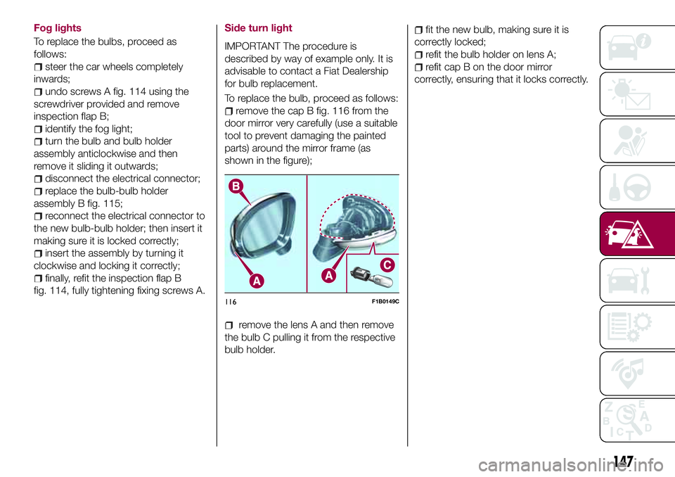
fig. 114, fully tightening fixing screws A.Side turn light
IMPORTANT The procedure is
described by way of example only. It is
advisable to contact a Fiat Dealership
for bulb replacement.
To replace the bulb, proceed as follows:
remove the cap B fig. 116 from the
door mirror very carefully (use a suitable
tool to prevent damaging the painted
parts) around the mirror frame (as
shown in the figure);
remove the lens A and then remove
the bulb C pulling it from the respective
bulb holder.
fit the new bulb, making sure it is
correctly locked;
refit the bulb holder on lens A;
refit cap B on the door mirror
correctly, ensuring that it locks correctly.
116F1B0149C
147
Page 155 of 284

ENGINE COMPARTMENT FUSE BOX
USERSFUSE AMPERE
HornF10 10
Power supply for cigar lighter/power socket F84 20
DASHBOARD FUSE BOX
USERSFUSE AMPERE
Front electric window (passenger side) F33 20
Front electric window (driver side) F34 20
Supply for
Uconnect™system, Climate Control system, Electric door mirror folding,
EOBD system, USB port/AUX socket, rear side roof lights
(versions with sun roof)F36 15
Dead Lock device (Driver side door unlocking for
versions/markets, where provided)/Door unlocking/Central
locking/Electric tailgate unlockingF38 20
Rear left electric window F47 20
Rear right electric window F48 20
153
Page 194 of 284

used for cleaning the rear view mirror.
Do not spray the detergent directly on
the glass.
Cleaning the window with hot water
could cause the removal of any labels.
WINDSCREEN / REAR
WINDOW WIPERS
Raising the windscreen wipers
If you need to lift the windscreen wiper
blades (e.g. in case of snow or when
they need to be replaced), you need to
activate the "Service Position" function
(see paragraph "Windscreen/Rear
window wiper" in the "Knowing your
vehicle" chapter).
To lower the blades, set the ignition
device to MAR-ON.
IMPORTANT Place the blades back in
contact with the windscreen before
activating the windscreen wiper again
and/or setting the ignition device to
MAR-ON.
Replacing the windscreen wiper
blades
Proceed as follows:
raise the wiper arm, press button A
fig. 162 of the attachment spring and
remove the blade from the arm;
fit the new blade, inserting the tab in
the dedicated housing in the arm and
checking that it is locked;
lower the wiper arm on the
windscreen.
IMPORTANT Do not operate the
windscreen wiper with the blades lifted
from the windscreen.
Replacing the rear window wiper
blade
Proceed as follows:
widen the two tabs as shown by the
arrows and rotate cover A
fig. 163 outwards;
undo nut B and remove arm C from
the central pin;
correctly align the new arm;
fully tighten nut B and then refit
cover A.
IMPORTANT Do not operate the rear
window wiper with the blade lifted from
the rear window.
NOZZLES
Windscreen washer
The window washer nozzles are fixed. If
there is no jet of fluid, firstly check that
there is fluid in the reservoir (see
paragraph “Engine compartment” in
this chapter). Then check that the
nozzle holes are not clogged; use a
needle to unblock them if necessary.
IMPORTANT In versions with sun roof,
make sure that the roof is closed before
operating the windscreen washer
nozzles.
Rear window washer
The rear window washer nozzle is fixed.
The jet nozzle is located at the side of
the third brake light.
162F1B0302C163F1B0303C
192
SERVICING AND MAINTENANCE