2017 FIAT 500L LIVING change wheel
[x] Cancel search: change wheelPage 22 of 240
SIDE LIGHTS AND
DIPPED BEAM
HEADLIGHTS
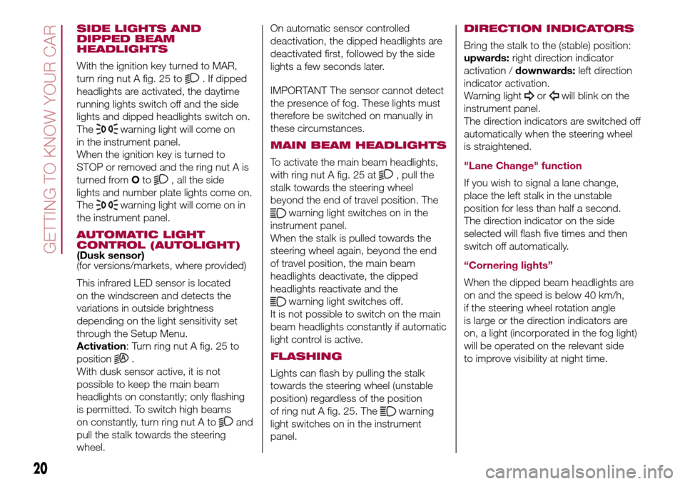
With the ignition key turned to MAR,
turn ring nut A fig. 25 to
. If dipped
headlights are activated, the daytime
running lights switch off and the side
lights and dipped headlights switch on.
The
warning light will come on
in the instrument panel.
When the ignition key is turned to
STOP or removed and the ring nut A is
turned fromOto
, all the side
lights and number plate lights come on.
The
warning light will come on in
the instrument panel.
AUTOMATIC LIGHT
CONTROL (AUTOLIGHT)
(Dusk sensor)
(for versions/markets, where provided)
This infrared LED sensor is located
on the windscreen and detects the
variations in outside brightness
depending on the light sensitivity set
through the Setup Menu.
Activation: Turn ring nut A fig. 25 to
position
.
With dusk sensor active, it is not
possible to keep the main beam
headlights on constantly; only flashing
is permitted. To switch high beams
on constantly, turn ring nut A to
and
pull the stalk towards the steering
wheel.On automatic sensor controlled
deactivation, the dipped headlights are
deactivated first, followed by the side
lights a few seconds later.
IMPORTANT The sensor cannot detect
the presence of fog. These lights must
therefore be switched on manually in
these circumstances.
MAIN BEAM HEADLIGHTS
To activate the main beam headlights,
with ring nut A fig. 25 at
, pull the
stalk towards the steering wheel
beyond the end of travel position. The
warning light switches on in the
instrument panel.
When the stalk is pulled towards the
steering wheel again, beyond the end
of travel position, the main beam
headlights deactivate, the dipped
headlights reactivate and the
warning light switches off.
It is not possible to switch on the main
beam headlights constantly if automatic
light control is active.
FLASHING
Lights can flash by pulling the stalk
towards the steering wheel (unstable
position) regardless of the position
of ring nut A fig. 25. The
warning
light switches on in the instrument
panel.
DIRECTION INDICATORS
Bring the stalk to the (stable) position:
upwards:right direction indicator
activation /downwards:left direction
indicator activation.
Warning light
orwill blink on the
instrument panel.
The direction indicators are switched off
automatically when the steering wheel
is straightened.
"Lane Change" function
If you wish to signal a lane change,
place the left stalk in the unstable
position for less than half a second.
The direction indicator on the side
selected will flash five times and then
switch off automatically.
“Cornering lights”
When the dipped beam headlights are
on and the speed is below 40 km/h,
if the steering wheel rotation angle
is large or the direction indicators are
on, a light (incorporated in the fog light)
will be operated on the relevant side
to improve visibility at night time.
20
GETTING TO KNOW YOUR CAR
Page 71 of 240

Driving in special conditions
In certain driving conditions, such as,
for example: driving around a bend (see
fig. 63) / small vehicles and/or vehicles
not aligned with the driving lane (see fig.
64) / lane change by other vehicles
(see fig. 65) the system operation might
be unexpected or delayed. Pay the
utmost attention, keeping control of the
vehicle to drive in complete safety.
iTPMS (indirect Tyre
Pressure Monitoring
System)
(for versions/markets, where provided)
44) 45) 46) 47) 48) 49)
The iTPMS can monitor the tyre inflation
status through the wheel speed
sensors. The system warns the driver if
one or more tyres are flat by switching
on the warning light
on the
instrument panel and a warning
message on the display, along with an
acoustic signal.
If one tyre only is flat, the system can
indicate its position: it is in any case
recommended to check the pressure
on all four tyres.
This indication is displayed also when
turning the engine off and on again until
the "Reset" procedure is carried out.
"Reset" procedure
The iTPMS needs an initial "self-
learning" phase (with length dependingon the driving style and road conditions:
optimal conditions being driven on a
straight road at 80 km/h for at least 20
minutes) which starts when the "Reset"
procedure is carried out.
The "Reset" procedure must be carried
out:
❒each time tyre pressure is modified;
❒when even only one tyre is changed;
❒when tyres are rotated/inverted;
❒when the space-saver wheel is fitted.
Before carrying out the "Reset"
procedure, inflate the tyres to the rated
pressure values specified in the inflation
pressure table (see the "Wheels"
paragraph in the "Technical
specifications" chapter).
If the "Reset" procedure is not carried
out, in all above cases, the
warning
light may give false indications on
one or more tyres.
To carry out the "Reset" procedure,
with the vehicle stopped and the
ignition device at MAR, use the Setup
Menu as follows:
❒briefly press the
button fig. 65a:
the display will show "Reset";
❒press the
button or the
button to select ("Yes" or "No");
63F0Y0320C
64F0Y0321C
65F0Y0322C
69
❒briefly press thebutton: the
display will show "Confirm";
❒press the
button or the
button to select ("Yes" to "Reset"
or "No" to exit the screen);
Page 76 of 240
PRETENSIONERS
71) 72) 73) 74)50)
The vehicle is equipped with front seat
belt pretensioners, which draw back
the seat belts by several centimetres in
the event of a strong frontal impact.
This guarantees the perfect adherence
of the seat belts to the occupant's
bodies before the retention action
begins.
It is evident that the pretensioners have
been activated when the belt withdraws
toward the retractor.
This vehicle is also equipped with a
second pretensioner (fitted in the kick
plate area). Its activation is signalled by
the shortening of the metal cable.
A slight discharge of smoke may be
produced during the activation of the
pretensioner which is not harmful and
does not indicate any fire hazard.
The pretensioner does not require any
maintenance or lubrication: any
changes to its original conditions will
invalidate its efficiency.
If, due to unusual natural events (floods,
sea storms, etc.), the device has been
affected by water and/or mud, contact
a Fiat Dealership to have it replaced.IMPORTANT To obtain the highest
degree of protection from the action of
the pretensioner, wear the seat belt
tight to the torso and pelvis.
LOAD LIMITERS
To increase safety in the event of an
accident, the front seat belt retractors
contain a load limiter which controls the
force acting on the chest and
shoulders during the belt restraining
action in the event of a head-on
collision.
GENERAL
INSTRUCTIONS FOR
USING THE SEAT BELTS
Respect and ensure that all the other
occupants of the vehicle comply with
the local laws in force regarding the use
of seat belts. Always fasten the seat
belts before setting off.
Seat belts must also be worn by
pregnant women: the risk of injury in
the event of an accident is reduced for
them and the unborn child if they are
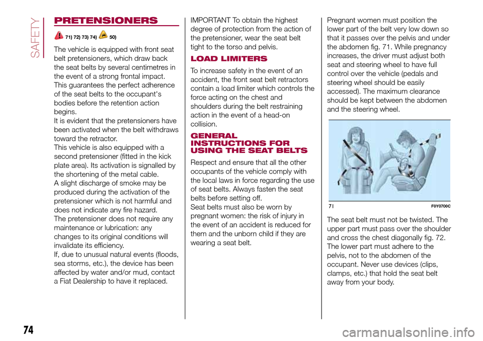
wearing a seat belt.Pregnant women must position the
lower part of the belt very low down so
that it passes over the pelvis and under
the abdomen fig. 71. While pregnancy
increases, the driver must adjust both
seat and steering wheel to have full
control over the vehicle (pedals and
steering wheel should be easily
accessed). The maximum clearance
should be kept between the abdomen
and the steering wheel.
The seat belt must not be twisted. The
upper part must pass over the shoulder
and cross the chest diagonally fig. 72.
The lower part must adhere to the
pelvis, not to the abdomen of the
occupant. Never use devices (clips,
clamps, etc.) that hold the seat belt
away from your body.
71F0Y0700C
74
SAFETY
Page 111 of 240
HAZARD WARNING
LIGHTS
CONTROL
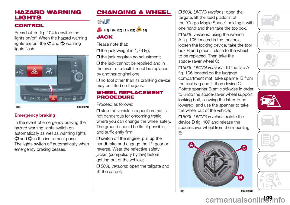
Press button fig. 104 to switch the
lights on/off. When the hazard warning
lights are on, the
andwarning
lights flash.
Emergency braking
In the event of emergency braking the
hazard warning lights switch on
automatically as well as warning lights
andin the instrument panel.
The lights switch off automatically when
emergency braking ceases.
CHANGING A WHEEL
118) 119) 120) 121) 122)63)
JACK
Please note that:
❒the jack weight is 1,76 kg;
❒the jack requires no adjustment;
❒the jack cannot be repaired and in
the event of a fault it must be replaced
by another original one;
❒no tool other than its cranking device
may be fitted on the jack.
WHEEL REPLACEMENT
PROCEDURE
Proceed as follows:
❒stop the vehicle in a position that is
not dangerous for oncoming traffic
where you can change the wheel safely.
The ground should be flat if possible,
and sufficiently firm;
❒switch off the engine, pull up the
handbrake and engage the 1
stgear or
reverse. Wear the reflective safety
jacket (compulsory by law) before
getting out of the vehicle;
❒500L versions: open the tailgate and
lift the carpet;❒500L LIVING versions: open the
tailgate, lift the load platform of
the "Cargo Magic Space" holding it with
one hand and then take the toolbox.
❒500L versions: using the wrench
A fig. 105 located in the tool box,
loosen the locking device, take the tool
box B and place it close to the wheel
to be replaced. Then take the
space-saver wheel C;
❒500L LIVING versions: lift the flap A
fig. 106 located on the luggage
compartment mat, take spanner B from
the tool bag and fit it on device C.
Rotate spanner B anticlockwise in order
to undo the space-saver wheel support
locking bolt, allowing the latter to be
lowered, and use the spanner to take
the wheel out of the vehicle;
❒500L LIVING versions: rotate the
device D fig. 107 and release the
space-saver wheel from the mounting
E;
104F0Y0037C
105F0Y0096C
109
Page 112 of 240
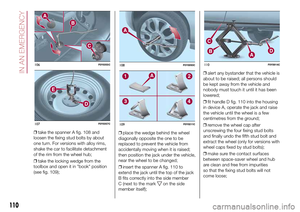
❒take the spanner A fig. 108 and
loosen the fixing stud bolts by about
one turn. For versions with alloy rims,
shake the car to facilitate detachment
of the rim from the wheel hub;
❒take the locking wedge from the
toolbox and open it in "book" position
(see fig. 109);❒place the wedge behind the wheel
diagonally opposite the one to be
replaced to prevent the vehicle from
accidentally moving when it is raised;
then position the jack under the vehicle,
near the wheel to be changed;
❒insert the spanner A fig. 110 to
extend the jack until the top of the jack
B fits correctly into the side member
C (next to the mark
on the side
member itself);❒alert any bystander that the vehicle is
about to be raised; all persons should
be kept away from the vehicle and
nobody must touch it until it has been
lowered;
❒fit handle D fig. 110 into the housing
in device A, operate the jack and raise
the vehicle until the wheel is a few
centimetres from the ground;
❒remove the wheel cap after
unscrewing the four fixing stud bolts
and finally undo the fifth stud bolt and
extract the wheel (only for versions with
wheel caps fixed by stud bolts);
❒make sure the contact surfaces
between space-saver wheel and hub
are clean and free from impurities
so that the fixing stud bolts will not
come loose;
106F0Y0355C
107F0Y0357C
108F0Y0093C
109F0Y0211C
110F0Y0014C
110
IN AN EMERGENCY
Page 114 of 240
❒fit the standard wheel inserting the 5
stud bolts into the holes;
❒press-fit the wheel cap, aligning the
special splining (on the cap) with the
inflation valve;
❒using the spanner provided, tighten
the fixing stud bolts;
❒lower the vehicle and remove the
jack;
❒using the spanner provided, fully
tighten the stud bolts in the sequence
shown previously.
Versions with alloy wheels
❒insert the wheel on the hub and using
the spanner provided tighten the stud
bolts;
❒lower the vehicle and remove the
jack;
❒using the spanner provided, fully
tighten the 5 stud bolts in the sequence
shown;❒reinstall the hub cap, taking care to
position the three plastic pins in the
dedicated seats on the wheel. Slightly
press the cap to prevent any damage
to the plastic pins.
IMPORTANT If it is not fitted properly,
the hub cap may detach itself when the
car is running.
After tyre replacement
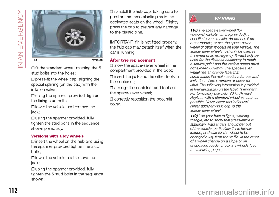
❒stow the space-saver wheel in the
compartment provided in the boot;
❒insert the jack and the other tools in
the container;
❒arrange the container and tools on
the space-saver wheel;
❒correctly reposition the boot stiff
cover.
WARNING
118)The space-saver wheel (for
versions/markets, where provided) is
specific to your vehicle, do not use it on
other models, or use the space-saver
wheel of other models on your vehicle. The
space-saver wheel must only be used in
the event of an emergency. It must only be
used for the distance necessary to reach
a service point and the vehicle speed must
not exceed 80 km/h. The space-saver
wheel has an orange label that
summarises the main cautions for use and
limitations. Never remove or cover the
label. The following information is provided
in four languages on the label: "Important!
For temporary use only! 80 km/h max!
Replace with a standard wheel as soon as
possible. Never cover this indication".
Never apply any hub cap to the
space-saver wheel.
119)Use your hazard lights, warning
triangle, etc to show that your vehicle is
stationary. Passengers should get out
of the vehicle, particularly if it is heavily
loaded, and wait for the wheel to be
changed away from the traffic. In the event
of a wheel change on a slope or on
unsurfaced roads, chock the wheels (see
the following pages).
114F0Y0368C
112
IN AN EMERGENCY