Page 184 of 350

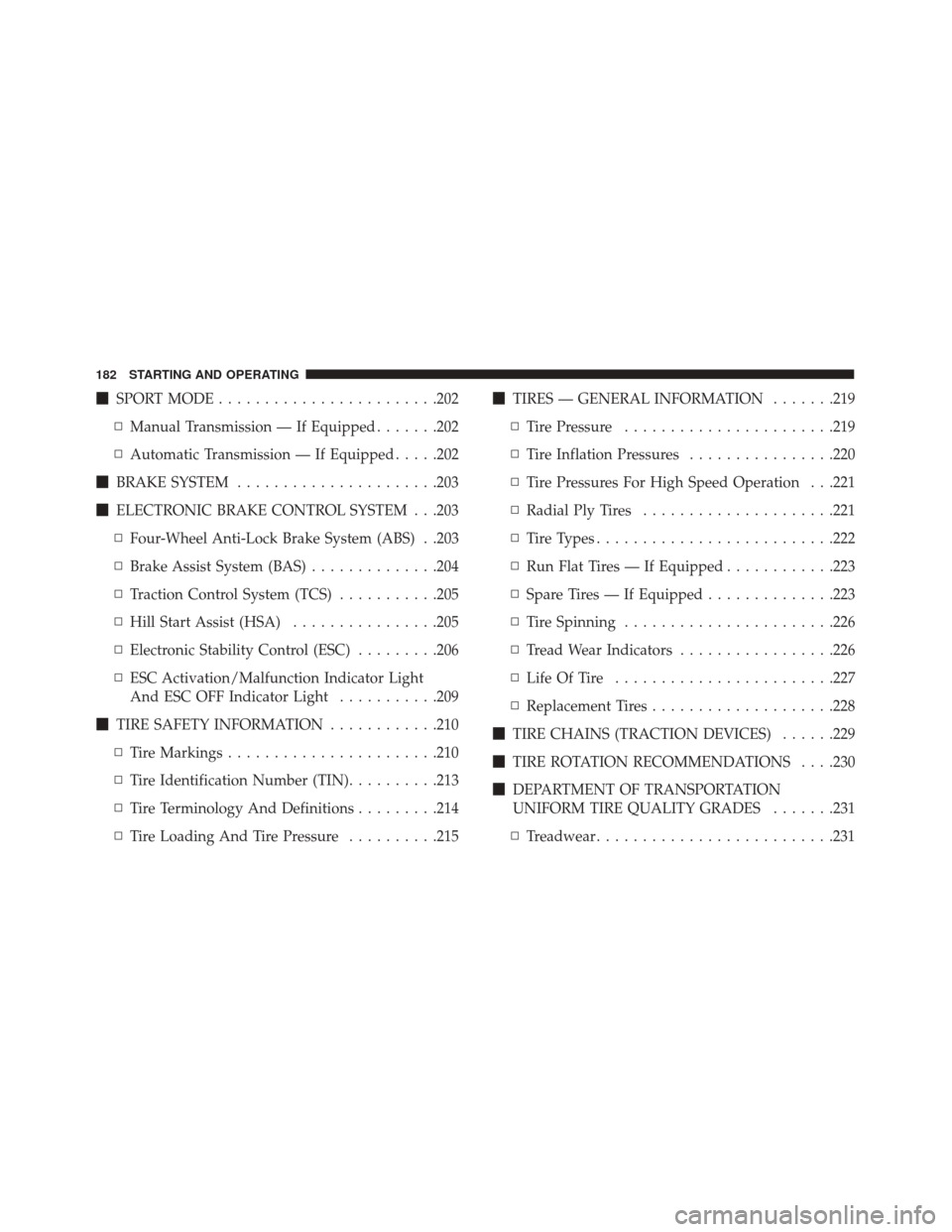
�SPORT MODE ....................... .202
▫ Manual Transmission — If Equipped .......202
▫ Automatic Transmission — If Equipped .....202
� BRAKE SYSTEM ..................... .203
� ELECTRONIC BRAKE CONTROL SYSTEM . . .203
▫ Four-Wheel Anti-Lock Brake System (ABS) . .203
▫ Brake Assist System (BAS) ..............204
▫ Traction Control System (TCS) ...........205
▫ Hill Start Assist (HSA) ................205
▫ Electronic Stability Control (ESC) .........206
▫ ESC Activation/Malfunction Indicator Light
And ESC OFF Indicator Light ...........209
� TIRE SAFETY INFORMATION ............210
▫ Tire Markings ...................... .210
▫ Tire Identification Number (TIN) ..........213
▫ Tire Terminology And Definitions .........214
▫ Tire Loading And Tire Pressure ..........215�
TIRES — GENERAL INFORMATION .......219
▫ Tire Pressure ...................... .219
▫ Tire Inflation Pressures ................220
▫ Tire Pressures For High Speed Operation . . .221
▫ Radial Ply Tires .....................221
▫ Tire Types ......................... .222
▫ Run Flat Tires — If Equipped ............223
▫ Spare Tires — If Equipped ..............223
▫ Tire Spinning ...................... .226
▫ Tread Wear Indicators .................226
▫ Life Of Tire ....................... .227
▫ Replacement
Tires ....................228
� TIRE CHAINS (TRACTION DEVICES) ......229
� TIRE ROTATION RECOMMENDATIONS . . . .230
� DEPARTMENT OF TRANSPORTATION
UNIFORM TIRE QUALITY GRADES .......231
▫ Treadwear ......................... .231
182 STARTING AND OPERATING
Page 185 of 350

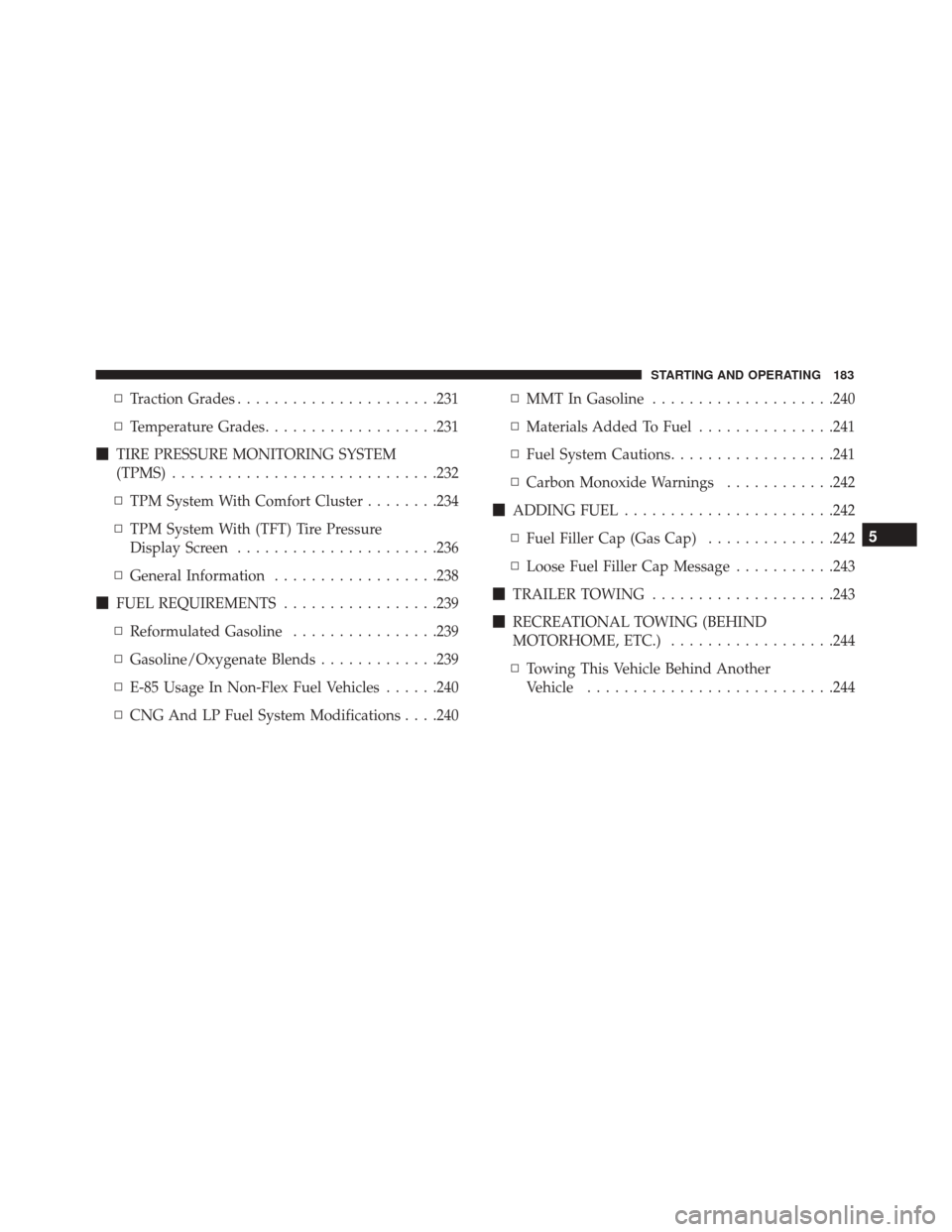
▫Traction Grades ..................... .231
▫ Temperature Grades ...................231
� TIRE PRESSURE MONITORING SYSTEM
(TPMS) ............................ .232
▫ TPM System With Comfort Cluster ........234
▫ TPM System With (TFT) Tire Pressure
Display Screen ..................... .236
▫ General Information ..................238
� FUEL REQUIREMENTS .................239
▫ Reformulated Gasoline ................239
▫ Gasoline/Oxygenate Blends .............239
▫ E-85 Usage In Non-Flex Fuel Vehicles ......240
▫ CNG And LP Fuel System Modifications . . . .240 ▫
MMT In Gasoline ....................240
▫ Materials Added To Fuel ...............241
▫ Fuel System Cautions ..................241
▫ Carbon Monoxide Warnings ............242
� ADDING FUEL ...................... .242
▫ Fuel Filler Cap (Gas Cap) ..............242
▫ Loose Fuel Filler Cap Message ...........243
� TRAILER TOWING ....................243
� RECREATIONAL TOWING (BEHIND
MOTORHOME, ETC.) ..................244
▫ Towing This Vehicle Behind Another
Vehicle .......................... .244
5
STARTING AND OPERATING 183
Page 206 of 350

WARNING!
•Pumping the Anti-Lock Brakes will diminish
their effectiveness and may lead to a collision.
Pumping makes the stopping distance longer. Just
press firmly on your brake pedal when you need
to slow down or stop.
• The Anti-Lock Brake System (ABS) cannot pre-
vent the natural laws of physics from acting on
the vehicle, nor can it increase braking or steering
efficiency beyond that afforded by the condition
of the vehicle brakes and tires or the traction
afforded.
• The ABS cannot prevent collisions, including
those resulting from excessive speed in turns,
following another vehicle too closely, or hydro-
planing.
• The capabilities of an ABS-equipped vehicle
must never be exploited in a reckless or danger-
ous manner, which could jeopardize the user’s
safety or the safety of others.
When you are in a severe braking condition involving
the use of the ABS, you will experience some pedal drop
as the vehicle comes to a stop. This is the result of the
system reverting to the base brake system. Engagement of the ABS may be accompanied by a
pulsing sensation. You may also hear a clicking noise.
These occurrences are normal and indicate that the
system is functioning properly.
Brake Assist System (BAS)
The BAS is designed to optimize the vehicle’s braking
capability during emergency braking maneuvers. The
system detects an emergency braking situation by sens-
ing the rate and amount of brake application and then
applies optimum pressure to the brakes. This can help
reduce braking distances. The BAS complements the
Anti-Lock Brake System (ABS). Applying the brakes
very quickly results in the best BAS assistance. To
receive the benefit of the system, you must apply
continuous
braking pressure during the stopping se-
quence (do not “pump” the brakes). Do not reduce
brake pedal pressure unless braking is no longer de-
sired. Once the brake pedal is released, the BAS is
deactivated.
204 STARTING AND OPERATING
Page 212 of 350

TIRE SAFETY INFORMATION
Tire MarkingsNOTE:
•P (Passenger) — Metric tire sizing is based on U.S.
design standards. P-Metric tires have the letter “P”
molded into the sidewall preceding the size designa-
tion. Example: P215/65R15 95H.
• European — Metric tire sizing is based on European
design standards. Tires designed to this standard
have the tire size molded into the sidewall beginning
with the section width. The letter �P�is absent from
this tire size designation. Example: 215/65R15 96H.
• LT (Light Truck) — Metric tire sizing is based on U.S.
design standards. The size designation for LT-Metric
tires is the same as for P-Metric tires except for the
letters “LT” that are molded into the sidewall preced-
ing the size designation. Example: LT235/85R16.
• Temporary spare tires are designed for temporary
emergency use only. Temporary high pressure com-
pact spare tires have the letter “T” or “S” molded into
the sidewall preceding the size designation. Ex-
ample: T145/80D18 103M.
• High flotation tire sizing is based on U.S. design
standards and it begins with the tire diameter
molded into the sidewall. Example: 31x10.5 R15 LT.
1 — U.S. DOT Safety Stan-
dards Code (TIN) 4 — Maximum Load
2 — Size Designation 5 — Maximum Pressure
3 — Service Description 6 — Treadwear, Traction and Temperature Grades
210 STARTING AND OPERATING
Page 214 of 350

EXAMPLE:
Service Description: 95= Load Index
– A numerical code associated with the maximum load a tire can carry
H = Speed Symbol
– A symbol indicating the range of speeds at which a tire can carry a load corresponding to
its load index under certain operating conditions
– The maximum speed corresponding to the speed symbol should only be achieved under
specified operating conditions (i.e., tire pressure, vehicle loading, road conditions, and
posted speed limits)
Load Identification:
Absence of the following load identification symbols on the sidewall of the tire indicates a Standard Load (SL)
tire:
•XL = Extra load (or reinforced) tire, or
•LL= Light load tire or
•C, D, E, F, G = Load range associated with the maximum load a tire can carry at a specified pressure
Maximum Load – Maximum load indicates the maximum load this tire is designed to carry
Maximum Pressure – Maximum pressure indicates the maximum permissible cold tire inflation pressure for
this tire
212 STARTING AND OPERATING
Page 216 of 350

Tire Terminology And Definitions
TermDefinition
B-Pillar The vehicle B-Pillar is the structural member of the body located
behind the front door.
Cold Tire Inflation Pressure Cold tire inflation pressure is defined as the tire pressure after
the vehicle has not been driven for at least three hours, or driven
less than 1 mile (1.6 km) after sitting for a minimum of three
hours. Inflation pressure is measured in units of PSI (pounds per
square inch) or kPa (kilopascals).
Maximum Inflation Pressure The maximum inflation pressure is the maximum permissible
cold tire inflation pressure for this tire. The maximum inflation
pressure is molded into the sidewall.
Recommended Cold Tire Inflation Pressure Vehicle manufacturer’s recommended cold tire inflation pressure
as shown on the tire placard.
Tire Placard A label permanently attached to the vehicle describing the vehi-
cle’s loading capacity, the original equipment tire sizes and the
recommended cold tire inflation pressures.
214 STARTING AND OPERATING
Page 217 of 350
Tire Loading And Tire Pressure
Tire And Loading Information Placard Location
NOTE:The proper cold tire inflation pressure is listed
on the driver ’s side B-Pillar or the rear edge of the
driver’s side door.
Example Tire Placard Location (Door)
Example Tire Placard Location (B-Pillar)
5
STARTING AND OPERATING 215
Page 218 of 350

Tire And Loading Information Placard
This placard tells you important information about the:
1. Number of people that can be carried in the vehicle.
2. Total weight your vehicle can carry.
3. Tire size designed for your vehicle.
4. Cold tire inflation pressures for the front, rear, andspare tires.
Loading
The vehicle maximum load on the tire must not exceed
the load carrying capacity of the tire on your vehicle.
You will not exceed the tire’s load carrying capacity if
you adhere to the loading conditions, tire size, and cold
tire inflation pressures specified on the Tire and Load-
ing Information placard in “Vehicle Loading” in the
“Starting And Operating” section of this manual.
NOTE: Under a maximum loaded vehicle condition,
gross axle weight ratings (GAWRs) for the front and
rear axles must not be exceeded. For further informa-
tion on GAWRs, vehicle loading, and trailer towing,
refer to “Vehicle Loading” in the “Starting And Oper-
ating” section of this manual.
To determine the maximum loading conditions of your
vehicle, locate the statement “The combined weight of
occupants and cargo should never exceed XXX kg or
XXX lbs” on the Tire and Loading Information placard.
The combined weight of occupants, cargo/luggage and
trailer tongue weight (if applicable) should never ex-
ceed the weight referenced here.
Tire And Loading Information Placard
216 STARTING AND OPERATING