2017 FIAT 124 SPIDER radio antenna
[x] Cancel search: radio antennaPage 25 of 300

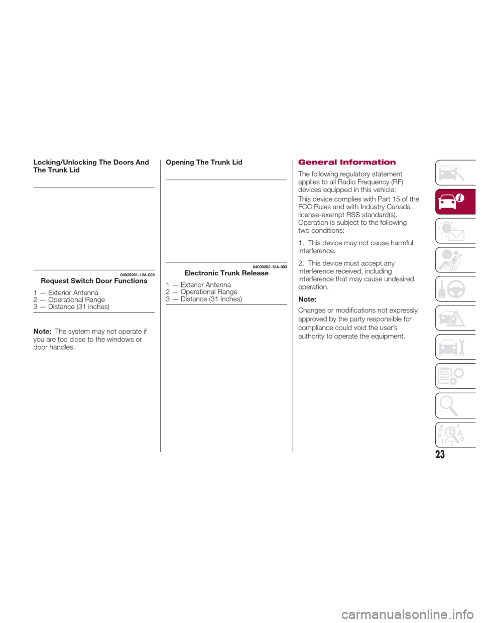
Locking/Unlocking The Doors And
The Trunk Lid
Note:The system may not operate if
you are too close to the windows or
door handles. Opening The Trunk LidGeneral Information
The following regulatory statement
applies to all Radio Frequency (RF)
devices equipped in this vehicle:
This device complies with Part 15 of the
FCC Rules and with Industry Canada
license-exempt RSS standard(s).
Operation is subject to the following
two conditions:
1. This device may not cause harmful
interference.
2. This device must accept any
interference received, including
interference that may cause undesired
operation.
Note:
Changes or modifications not expressly
approved by the party responsible for
compliance could void the user’s
authority to operate the equipment.
04020201-12A-003Request Switch Door Functions
1 — Exterior Antenna
2 — Operational Range
3 — Distance (31 inches)
04020202-12A-003Electronic Trunk Release
1 — Exterior Antenna
2 — Operational Range
3 — Distance (31 inches)
23
Page 62 of 300

8. At the garage door opener receiver
(motor-head unit) in the garage, locate
the “learn” or “smart” button. This can
usually be found where the hanging
antenna wire is attached to the
motorhead unit.
9. Firmly press and release the “learn”
or “smart” button (the name and color
of the button may vary by
manufacturer).
Note:Complete the programming
within 30 seconds.
10. Return to the vehicle and firmly
press, hold for two seconds and
release the programmed HomeLink
button. Repeat the “ press/hold/
release” sequence a second time, and,
depending on the brand of the garage
door opener (or other rolling code
equipped device), repeat this sequence
a third time to complete the
programming process. HomeLink
should now activate your rolling code
equipped device.
Note:
To program the remaining two
HomeLink buttons, begin with
“Programming” - step one.
For questions or comments,
please contact HomeLink at
www.homelink.com or
1-800-355-3515 .Gate Operator/Canadian
Programming
Canadian radio-frequency laws require
transmitter signals to “time-out” (or quit)
after several seconds of transmission -
which may not be long enough for
HomeLink to pick up the signal during
programming.
Similar to this Canadian law, some U.S.
gate operators are designed to
“time-out” in the same manner.
If you live in Canada or you are having
difficulties programming a gate operator
by using the “Programming”
procedures (regardless of where you
live), replace “Programming HomeLink”
step three with the following:
Note:If programming a garage door
opener or gate operator, it is advised to
unplug the device during the “cycling”
process to prevent possible
overheating.
1. Continue to press and hold the
HomeLink button while you press and
release -every two seconds (“cycle”)
your hand-held transmitter until the
frequency signal has successfully been
accepted by HomeLink (the indicator
light will flash slowly and then rapidly).
2. Proceed with the “Programming”
steps to complete.
Operating The System
Press the programmed HomeLink
button to operate a programmed
device.
The code will continue being
transmitted for a maximum of
20 seconds.
Reprogramming The
System
To program a device to HomeLink using
a HomeLink button previously trained,
follow these steps:
1. Press and hold the desired
HomeLink button. DO NOTrelease the
button;
2. The indicator light will begin to flash
after 20 seconds. Without releasing the
HomeLink button, proceed with
“Programming” - step one.
Erasing Programmed
Homelink Buttons
To erase the existing programming from
all three operating channels, press and
hold the two outside buttons 1 and
3 on the auto-dimming mirror until the
HomeLink indicator light begins to flash
after approximately 10 seconds.
Verify that the programming has been
erased when you resell the vehicle.
60
GETTING TO KNOW YOUR VEHICLE
Page 166 of 300

A antenna for a radio transmitter is
installed to the vehicle.
The vehicle is moving towards a tall
or square curbstone.
An obstruction is too close to the
sensor.
The following types of obstructions
may not be detected:
Thin objects such as wire or rope.
Things which absorb sonic waves
easily such as rain or snow.
Angular shaped objects.
Very tall objects, and those which
arewideatthetop.
Small, short objects.
Obstructions under the bumper
may not be detected. Obstructions
that are lower than the bumper or thin
which may have been initially detected
but are no longer detected as the
vehicle approaches more closely.
Always have the system inspected
by an Authorized Dealer if any shock is
applied to the bumpers, even in a
minor accident. If the sensors are
deviated, they cannot detect
obstructions.
The system may have a malfunction
if the audible signal does not operate.
Contact an Authorized Dealer.
The beeper which indicates a
system malfunction may not be heard
if the ambient temperature is extremely
cold, or mud, ice, or snow adheres to
the sensor area. Remove any foreign
material from the sensor area.
When installing a trailer hitch,
contact an Authorized Dealer.
Caution!
Only have repairs on the bumper in the
area of the sensors carried out by a
Authorized Dealer. Repairs on the bumper
that are not carried out properly may
compromise the operation of the parking
sensors.
Only have the bumpers repainted or any
retouches to the paint work in the area of
the sensors carried out by a Authorized
Dealer. Incorrect paint application could
affect the operation of the parking sensors.
Sensor Detection Range
The sensors detect obstructions within
the following range:
Lateral Detection Range :
19 inches (50 cm)
Rear Detection Range :59inches
(150 cm)
System Operation
The system is operational when the
ignition is switched ON and the gear
selector is shifted to the Reverse (R)
position. When the audible signal
activates the system is enabled for use.
164
STARTING AND OPERATING
Page 299 of 300

INSTALLATION OF RADIO TRANSMITTING
EQUIPMENT
Special design considerations are incorporated into this
vehicle’s electronic system to provide immunity to radio
frequency signals. Mobile two-way radios and telephone
equipment must be installed properly by trained person-
nel. The following must be observed during installation.
The positive power connection should be made directly
to the battery and fused as close to the battery as possible.
The negative power connection should be made to body
sheet metal adjacent to the negative battery connection.
This connection should not be fused.
Antennas for two-way radios should be mounted on the
roof or the rear area of the vehicle. Care should be used
in mounting antennas with magnet bases. Magnets may
affect the accuracy or operation of the compass on
vehicles so equipped.The antenna cable should be as short as practical and
routed away from the vehicle wiring when possible. Use
only fully shielded coaxial cable.
Carefully match the antenna and cable to the radio to
ensure a low Standing Wave Ratio (SWR).
Mobile radio equipment with output power greater than
normal may require special precautions.
All installations should be checked for possible interfer-
ence between the communications equipment and the
vehicle’s electronic systems.