2017 FIAT 124 SPIDER coolant
[x] Cancel search: coolantPage 47 of 300

Have the air conditioner checked before
the weather gets hot. A lack of
refrigerant may make the air conditioner
less efficient. The refrigerant
specifications are indicated on a label
(A or B depending on the market)
attached to the inside of the engine
compartment. Check the label before
refilling the refrigerant. If the wrong type
of refrigerant is used, it could result in a
serious malfunction of the air
conditioner. For details, contact your
Authorized Dealership.
Caution!
The system uses a coolant that is
compatible with the laws in force in the
countries where the vehicle is sold, R134a
or R1234yf (indicated on a specific plate in
the engine compartment). The use of other
coolants affects the efficiency and condition
of the system. Also the compressor
coolants used must be compatible with the
indicated coolant.
Vent Operation
Adjusting The Vents
To adjust the direction of air flow, move
the vent adjustment knob.
Note:When using the air conditioner in
humid conditions, fog may blow from
the vents. This is a result of humid air
being suddenly cooled and does not
indicate a system malfunction.
Center Vents (Driver) and Side
Vents
Center and side vents are located on
the dashboard.
Air vent open/close:the air vents can
be fully opened and closed by operating
knob1(A=open/B=close).
Air flow direction adjustment : operate
knob 1 to adjust the center vents to the
desired position.
GUID-06010100121001Label Location
06010201-033-001Side Air Vents
06010201-033-666Operating the Side Air Vents
1 — Air Vent Knob
A — Open Position
B — Closed Position
45
Page 52 of 300
Outside Air Position: (LED off)
Outside air is allowed to enter the
cabin. Use this mode for ventilation or
windshield defrosting.
Note:
Do not use the Outside Air Position in
cold or rainy weather is dangerous as it
will cause the windows to fog up. Your
vision will be hampered, which could
lead to a serious accident.
6 – A/C Button
Push the A/C Button to turn on the air
conditioner.
The LED on the switch will illuminate
when the Blower Control Knob is in any
position except the OFF position.
Push the button again to turn off the air
conditioner.
Note: The air conditioner may not
function when the outside temperature
approaches 32 °F (0 °C).
Heating
Proceed as follows:
1. Set the Mode Selector Knob to
the
position.
2. Set the Air Recirculation Button to
the outside air position.
3. Set the Temperature Control Dial to
the hot position. 4. Set the Blower Control Knob to the
desired speed.
5. If dehumidified heating is desired,
turn on the air conditioner.
If the windshield fogs up easily, set the
Mode Selector Knob to the
position.
If cooler air is desired at face level, set
the Mode Selector Knob to the
position and adjust the Temperature
Control Knob to maintain comfort.
The floor vents will blow warmer air
while the side air vents will blow cooler
air (except when the temperature
control dial is set at the maximum hot
or cold position).
Cooling (With Air
Conditioner)
Proceed as follows:
1. Set the Mode Selector Knob to
the
position.
2. Set the Temperature Control Knob
to the cold position.
3. Set the Blower Control Knob to the
desired speed.
4. Turn on the air conditioner by
pushing the A/C Button.
5. After cooling begins, adjust the
Blower Control Knob and Temperature
Control Knob as needed to maintain
comfort. Note:
If the air conditioner is used while
driving up large hills or in heavy traffic,
monitor the Engine Coolant
Temperature Warning Light to see if it
is illuminated or flashing. The air
conditioner may cause engine
overheating in these situations. If the
warning light is illuminated or flashing,
turn the air conditioning off
immediately.
When maximum cooling is desired,
set the Temperature Control Knob to
the extreme cold position, push the Air
Recirculation Button to activate the
recirculated air position, and then turn
the fan control dial fully clockwise.
If warmer air is desired at floor level,
set the Mode Selector Knob to the
position, and adjust the
Temperature Control Knob to maintain
comfort.
The floor vents will blow warmer air
while the side air vents will blow cooler
air (except when the temperature
control dial is set at the maximum hot
or cold position).
50
GETTING TO KNOW YOUR VEHICLE
Page 80 of 300
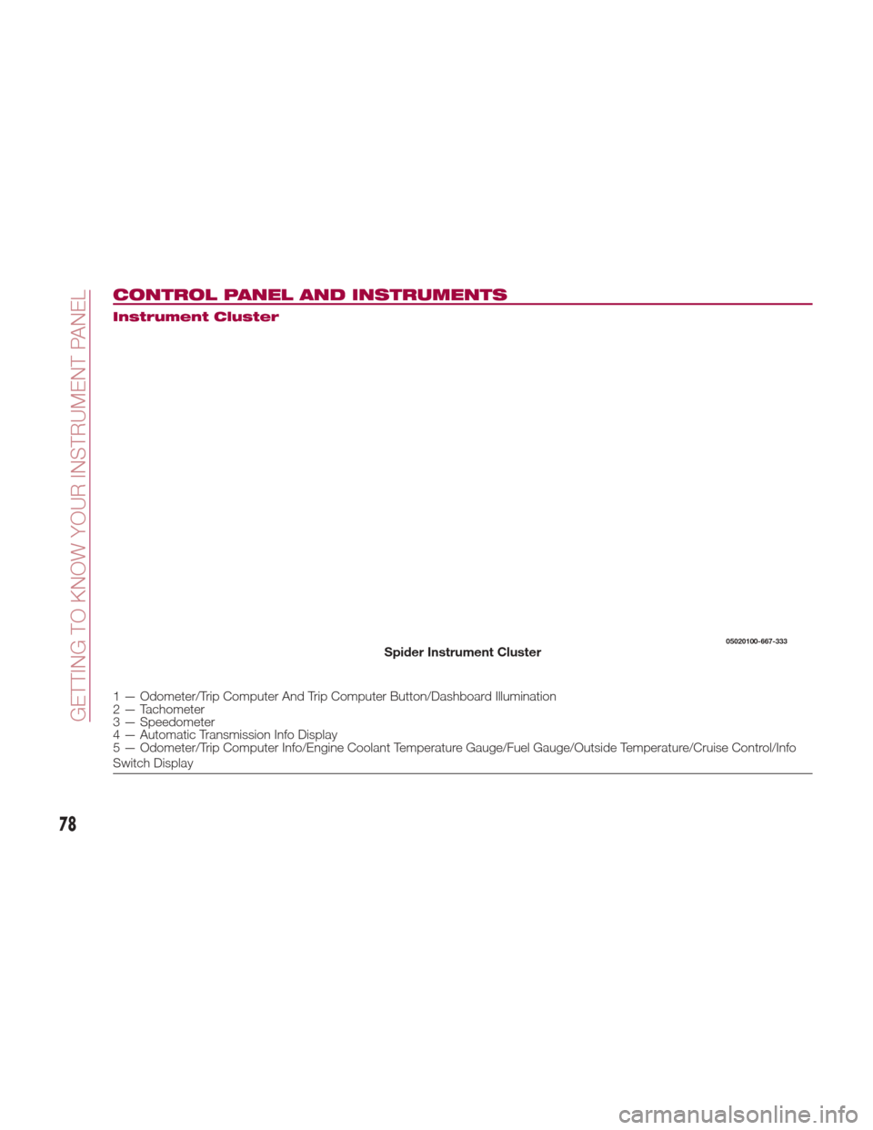
CONTROL PANEL AND INSTRUMENTS
Instrument Cluster
1 — Odometer/Trip Computer And Trip Computer Button/Dashboard Illumination
2 — Tachometer
3 — Speedometer
4 — Automatic Transmission Info Display
5 — Odometer/Trip Computer Info/Engine Coolant Temperature Gauge/Fuel Gauge/Outside Temperature/Cruise Control/Info
Switch Display
05020100-667-333Spider Instrument Cluster
78
GETTING TO KNOW YOUR INSTRUMENT PANEL
Page 84 of 300
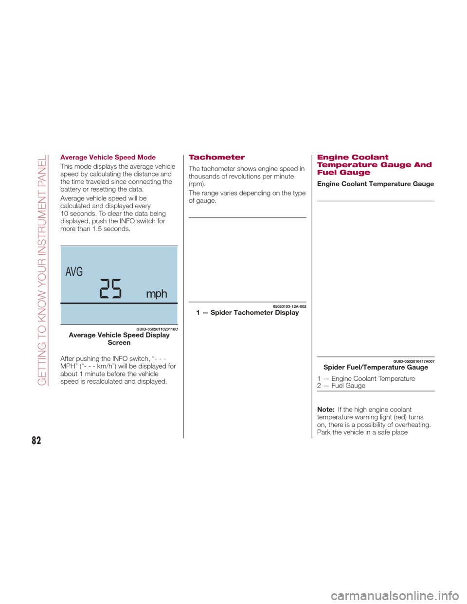
Average Vehicle Speed Mode
This mode displays the average vehicle
speed by calculating the distance and
the time traveled since connecting the
battery or resetting the data.
Average vehicle speed will be
calculated and displayed every
10 seconds. To clear the data being
displayed, push the INFO switch for
more than 1.5 seconds.
After pushing the INFO switch, “- - -
MPH” (“---km/h”)willbedisplayedfor
about 1 minute before the vehicle
speed is recalculated and displayed.Tachometer
The tachometer shows engine speed in
thousands of revolutions per minute
(rpm).
The range varies depending on the type
of gauge.
Engine Coolant
Temperature Gauge And
Fuel Gauge
Engine Coolant Temperature Gauge
Note:If the high engine coolant
temperature warning light (red) turns
on, there is a possibility of overheating.
Park the vehicle in a safe place
GUID-0502011020110CAverage Vehicle Speed Display Screen
05020103-12A-0021 — Spider Tachometer Display
GUID-0502010417A007Spider Fuel/Temperature Gauge
1 — Engine Coolant Temperature
2 — Fuel Gauge
82
GETTING TO KNOW YOUR INSTRUMENT PANEL
Page 85 of 300
immediately and take appropriate
measures. If the vehicle continues to be
driven, it could cause damage to the
engine.
Fuel Gauge
The fuel gauge 2 shows approximately
how much fuel is remaining in the tank
when the ignition is in the ON position.
We recommend keeping the tank over
1/4 full.
E= Empty
F= Full
If the low fuel warning light illuminates
or the fuel level is very low, refuel as
soon as possible.
Note:
After refueling, it may require some
time for the indicator to stabilize. In
addition, the indicator may deviate
while driving on a slope or curve since
the fuel moves in the tank.
The display indicating a quarter or
less remaining fuel has more segments
to show the remaining fuel level in
greater detail.
The direction of the arrow on the
fuel gauge indicates that the fuel door
lid is on the left side of the vehicle.
Outside Temperature
Display
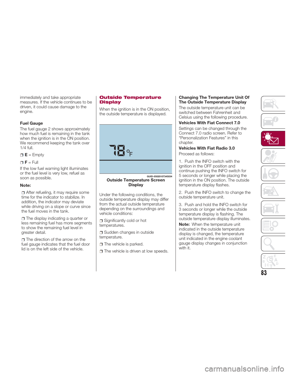
When the ignition is in the ON position,
the outside temperature is displayed.
Under the following conditions, the
outside temperature display may differ
from the actual outside temperature
depending on the surroundings and
vehicle conditions:
Significantly cold or hot
temperatures.
Sudden changes in outside
temperature.
The vehicle is parked.
The vehicle is driven at low speeds. Changing The Temperature Unit Of
The Outside Temperature Display
The outside temperature unit can be
switched between Fahrenheit and
Celsius using the following procedure.
Vehicles With Fiat Connect 7.0
Settings can be changed through the
Connect 7.0 radio screen. Refer to
“Personalization Features” in this
chapter.
Vehicles With Fiat Radio 3.0
Proceed as follows:
1. Push the INFO switch with the
ignition in the OFF position and
continue pushing the INFO switch for
5 seconds or longer while placing the
ignition in the ON position. The outside
temperature display flashes.
2. Push the INFO switch to change the
outside temperature unit.
3. Push and hold the INFO switch for
3 seconds or longer while the outside
temperature display is flashing. The
outside temperature display illuminates.
Note:
When the temperature unit
indicated in the outside temperature
display is changed, the temperature
unit indicated in the engine coolant
gauge display changes in conjunction
with it.
GUID-05020107345034Outside Temperature Screen Display
83
Page 92 of 300

WARNING LIGHTS
AND MESSAGES
Warning Lights And
Messages
Note:
The warning light in the instrument
panel appears together with a
dedicated message and/or acoustic
signal when applicable. These
indications are indicative and
precautionary and as such must not be
considered as exhaustive and/or
alternative to the information contained
in the Owner’s Manual, which you are
advised to read carefully in all cases.
Always refer to the information in this
chapter in the event of a failure
indication.
Failure indications displayed are
divided into two categories: serious
and less serious failures. Serious
failures are indicated by a repeated
and prolonged warning "cycle". Less
serious failures are indicated by a
warning "cycle" with a shorter duration.
The display cycle of both categories
can be interrupted. The instrument
panel warning light will stay on until the
cause of the failure is eliminated. Vehicles With Fiat Connect 7.0
The warning contents can be verified
on the audio system.
Proceed as follows:
If the warning light is turned on,
selecticon on the home screen to
display the application screen.
Select “ Warning Guidance ”to
display the current warnings.
Select the applicable warning to view
the warning details.
For the following warning/indicator lights:
Master Warning Light
Brake System Warning Light
ABS Warning Light
Charging System Warning Light
Engine Oil Warning Light
Electric Throttle Warning Light
Cold Start Warning Light
Check Engine Warning Light
Coolant Temperature Warning Light
Automatic Transmission Warning
Light
Power Steering Malfunction Indicator
Light
Air Bag/Seat Belt Pretensioner
System Warning Light
Check Fuel Cap Warning Light
Low Fuel Warning Light
Seat Belt Warning Light
Door Ajar Warning Light
Low Washer Fluid Level Warning
Light
Tire Pressure Monitoring System
Warning Light
KEY Warning Light
LED Headlight KEY Warning Light
BSM (Blind Spot Monitoring) OFF
Indicator Light
Wrench Indicator Light
TCS/DSC Indicator Light
DSC OFF Indicator Light
Security Indicator Light
Indicator Light
Passenger Air Bag Deactivation
Warning Light
The light turns on when the ignition is
switched on for an operation check,
and turns off a few seconds later or
when the engine is started. If the light
does not turn on or remains turned on,
have the vehicle inspected at an
Authorized Dealership.
Note:
Only for “Brake System Warning Light”:
the light turns on continuously when the
parking brake is applied.
90
GETTING TO KNOW YOUR INSTRUMENT PANEL
Page 95 of 300
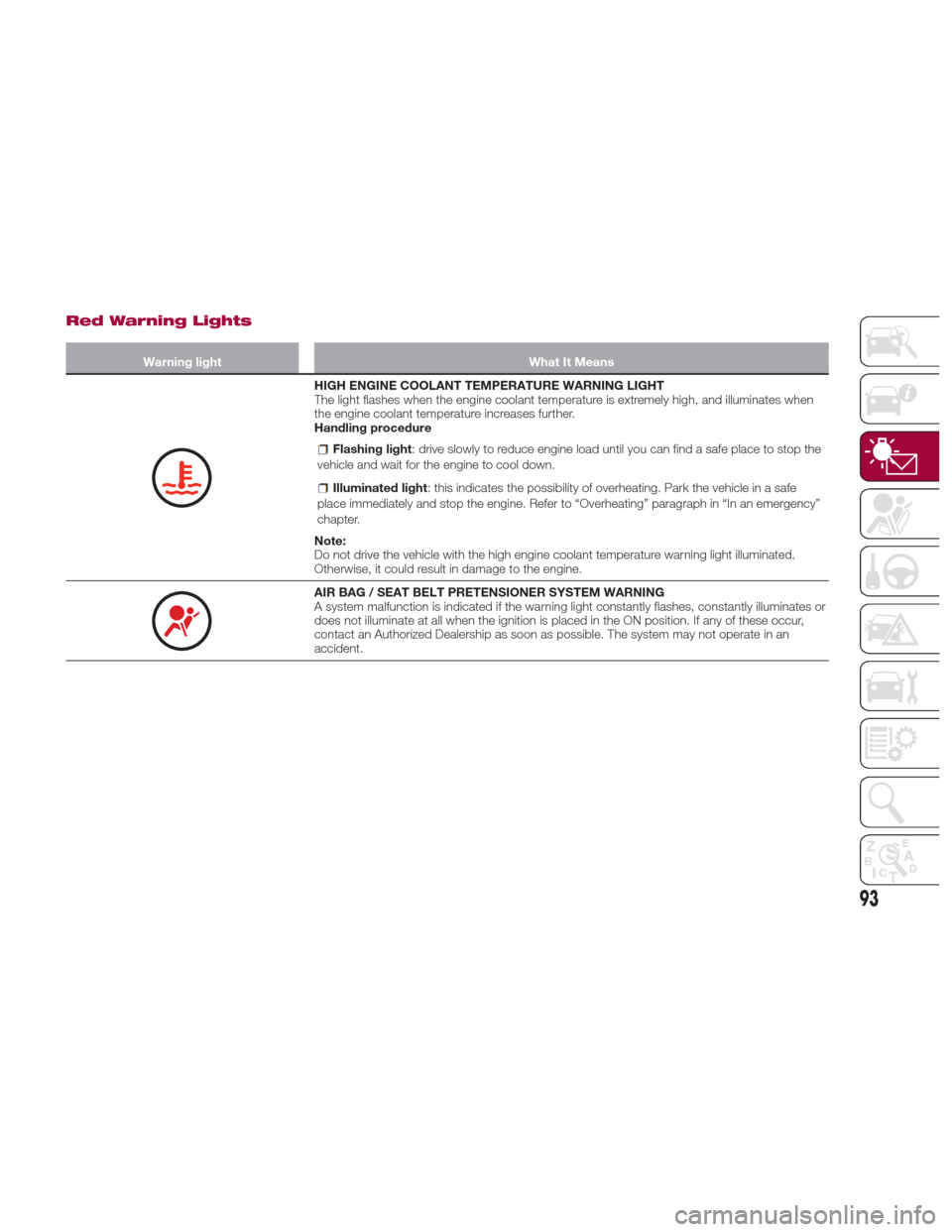
Red Warning Lights
Warning lightWhat It Means
HIGH ENGINE COOLANT TEMPERATURE WARNING LIGHT
The light flashes when the engine coolant temperature is extremely high, and illuminates when
the engine coolant temperature increases further.
Handling procedure
Flashing light: drive slowly to reduce engine load until you can find a safe place to stop the
vehicle and wait for the engine to cool down.
Illuminated light : this indicates the possibility of overheating. Park the vehicle in a safe
place immediately and stop the engine. Refer to “Overheating” paragraph in “In an emergency”
chapter.
Note:
Do not drive the vehicle with the high engine coolant temperature warning light illuminated.
Otherwise, it could result in damage to the engine.
AIR BAG / SEAT BELT PRETENSIONER SYSTEM WARNING
A system malfunction is indicated if the warning light constantly flashes, constantly illuminates or
does not illuminate at all when the ignition is placed in the ON position. If any of these occur,
contact an Authorized Dealership as soon as possible. The system may not operate in an
accident.
93
Page 105 of 300

Blue warning light
Warning lightWhat it means
MAIN BEAM HEADLIGHTS
The warning light switches on when the main beam headlights are turned on.
LOW ENGINE COOLANT TEMPERATURE INDICATOR LIGHT
The light illuminates continuously when the engine coolant temperature is low and turns off after
the engine is warm.
If the low engine coolant temperature indicator light remains illuminated after the engine has
been sufficiently warmed up, the temperature sensor could have a malfunction. Contact an
Authorized Dealership.
103