2017 DODGE GRAND CARAVAN door lock
[x] Cancel search: door lockPage 329 of 530
NOTE:There is a difference in temperature (in any condi-
tions other than full cold or full hot), between the upper
and lower outlets for added comfort. The warmer air goes
to the floor outlets. This feature gives improved comfort
during sunny but cool conditions.
13. Panel Mode Button
Air is directed through the outlets in the instrument
panel. These outlets can be adjusted for direction,
and turned on or off to control airflow.
NOTE: For maximum airflow to the rear, the center instru-
ment panel outlets can be directed toward the rear seat
passengers.
Economy Mode
If ECONOMY mode is desired, push the A/C button to
turn off the indicator light and the A/C compressor. Rotate
the temperature control knob to the desired temperature.
Also, make sure to select only Panel, Bi-Level or Floor
modes.
Max A/C
For maximum cooling use the A/C and Recirculation
mode buttons at the same time.
Rear Manual Climate Control — If Equipped
The Rear Manual Climate Control system has floor air
outlets at the rear of the right side sliding door, and
overhead outlets at each outboard rear seating position.
The unit provides warm or cool air through the floor and
upper outlets.
The rear blower and temperature controls for the rear seat
passengers are located in the headliner, near the center of
the vehicle.
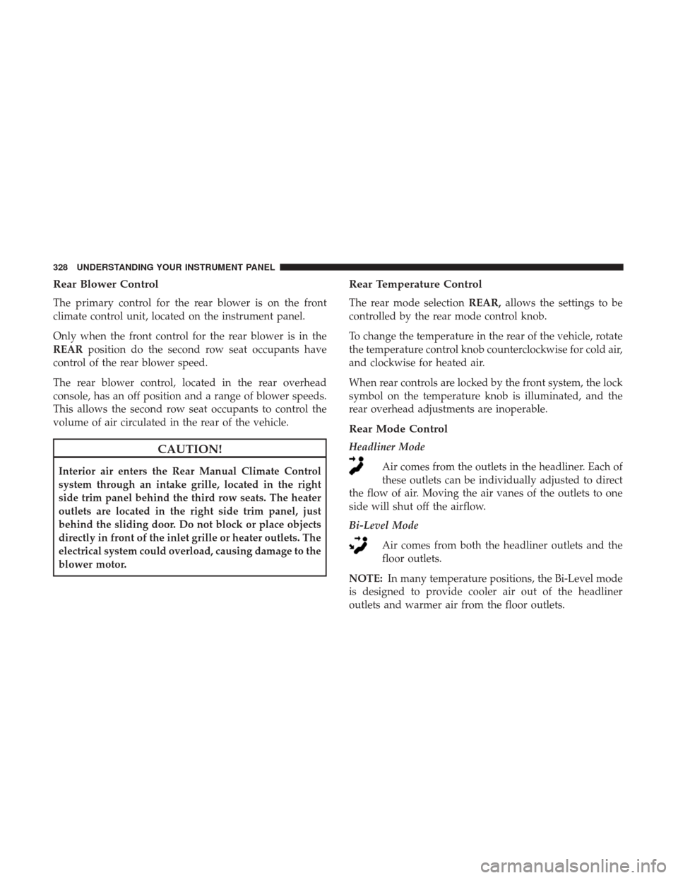
Rear Manual Climate Controls
1 — Rear Blower 3 — Rear Mode
2 — Rear Temperature 4 — Rear Climate Control Lock
4
UNDERSTANDING YOUR INSTRUMENT PANEL 327
Page 330 of 530
Rear Blower Control
The primary control for the rear blower is on the front
climate control unit, located on the instrument panel.
Only when the front control for the rear blower is in the
REARposition do the second row seat occupants have
control of the rear blower speed.
The rear blower control, located in the rear overhead
console, has an off position and a range of blower speeds.
This allows the second row seat occupants to control the
volume of air circulated in the rear of the vehicle.
CAUTION!
Interior air enters the Rear Manual Climate Control
system through an intake grille, located in the right
side trim panel behind the third row seats. The heater
outlets are located in the right side trim panel, just
behind the sliding door. Do not block or place objects
directly in front of the inlet grille or heater outlets. The
electrical system could overload, causing damage to the
blower motor.
Rear Temperature Control
The rear mode selection REAR,allows the settings to be
controlled by the rear mode control knob.
To change the temperature in the rear of the vehicle, rotate
the temperature control knob counterclockwise for cold air,
and clockwise for heated air.
When rear controls are locked by the front system, the lock
symbol on the temperature knob is illuminated, and the
rear overhead adjustments are inoperable.
Rear Mode Control
Headliner Mode
Air comes from the outlets in the headliner. Each of
these outlets can be individually adjusted to direct
the flow of air. Moving the air vanes of the outlets to one
side will shut off the airflow.
Bi-Level Mode
Air comes from both the headliner outlets and the
floor outlets.
NOTE: In many temperature positions, the Bi-Level mode
is designed to provide cooler air out of the headliner
outlets and warmer air from the floor outlets.
328 UNDERSTANDING YOUR INSTRUMENT PANEL
Page 336 of 530
Floor ModeAir comes from the floor outlets.
Rear Automatic Temperature Control (ATC) — If
Equipped
The rear ATC system has floor air outlets at the rear of the
right side sliding door, and overhead outlets at each
outboard rear seating position. The system provides heated
air through the floor outlets or cool, dehumidified air
through the headliner outlets.
The rear system temperature control is on the front ATC
panel located on the instrument panel.
Pushing the Rear Temperature Lock button on the front
ATC panel, illuminates a lock symbol in the rear display.
The rear temperature and air source are controlled from the
front ATC panel.
Rear second row occupants can only adjust the rear ATC
control when the Rear Temperature Lock button is turned
off.
The rear ATC system is located in the headliner, near the
center of the vehicle. 1. Push the Rear Temperature Lock button on the front
ATC panel. This turns off the Rear Temperature Lock
icon in the rear temperature knob.
2. Rotate the Rear Blower, Rear Temperature and the Rear Mode Control knobs to suit your comfort needs.
3. ATC is selected by adjusting the rear blower knob counterclockwise to AUTO.
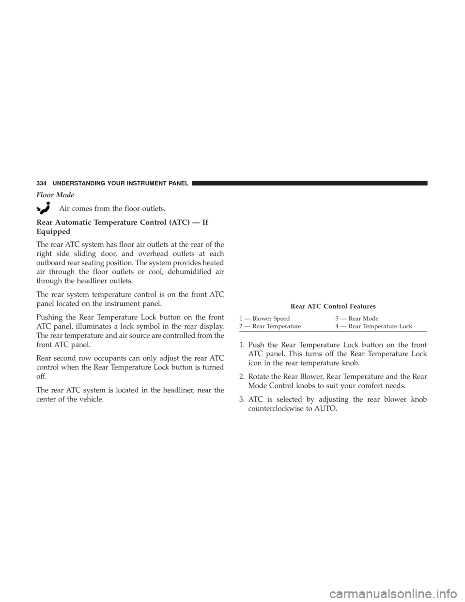
Rear ATC Control Features
1 — Blower Speed 3 — Rear Mode
2 — Rear Temperature 4 — Rear Temperature Lock
334 UNDERSTANDING YOUR INSTRUMENT PANEL
Page 337 of 530
Once the desired temperature is displayed, the ATC System
will automatically achieve and maintain that comfort level.
When the system is set up for your comfort level, it is not
necessary to change the settings. You will experience the
greatest efficiency by simply allowing the system to func-
tion automatically.
NOTE:
•It is not necessary to move the temperature settings. The
system automatically adjusts the temperature, mode and
fan speed to provide comfort as quickly as possible.
• The temperature can be displayed in English or Metric
units by selecting the “Display Units of Measure in”
customer-programmable feature. Refer to the “Instru-
ment Cluster Display” in this Section.
Rear Blower Control
The rear blower control knob can be manually set to off, or
any fixed blower speed, by rotating the knob from low to
high. This allows the rear seat occupants to control the
volume of air circulated in the rear of the vehicle.
CAUTION!
Interior air enters the Rear Automatic Temperature
Control System through an intake grille, located in the
right side trim panel behind the third row seats. The
heater outlets are located in the right side trim panel,
just behind the sliding door. Do not block or place
objects directly in front of the inlet grille or heater
outlets. The electrical system could overload causing
damage to the blower motor.
Rear Temperature Control
To change the temperature in the rear of the vehicle, rotate
the temperature knob counterclockwise to lower the tem-
perature, and clockwise to increase the temperature. The
rear temperature settings are displayed in the front ATC
panel.
When rear controls are locked by the front system, the Rear
Temperature Lock symbol on the temperature knob is
illuminated and any rear overhead adjustments are ig-
nored.
4
UNDERSTANDING YOUR INSTRUMENT PANEL 335
Page 406 of 530
Starting
The characteristics of E-85 fuel make it unsuitable for use
when ambient temperatures fall below 0°F (-18°C). In the
range of 0°F (-18°C) to 32°F (0°C), an increase in the time it
takes for your engine to start may be experienced, and a
deterioration in driveability (sags and/or hesitations) until
the engine is fully warmed up. These issues may be
improved with the use of seasonally adjusted E-85 fuel.
NOTE:Use of the engine block heater (if equipped) may
improve engine start time when using E-85 fuel when the
ambient temperature is less than 32°F (0°C).
Cruising Range
Because E-85 fuel contains less energy per gallon/liter than
gasoline, an increase in fuel consumption will be experi-
enced. The miles per gallon (mpg)/kilometers per liter and
the driving range will decrease by approximately 30%,
compared to gasoline operation.
Replacement Parts
All fuel and engine components in your Flexible Fuel
Vehicle (FFV) are designed to be compatible with ethanol.
Ethanol compatible service components are required.
CAUTION!
Replacing fuel system components with non-ethanol
compatible components can damage your vehicle.
Maintenance
CAUTION!
Do not use ethanol mixtures greater than 85% in your
vehicle. It will make it more difficult for your engine to
start under cold conditions, may affect drivability, and
could cause engine damage.
ADDING FUEL
Fuel Filler Cap (Gas Cap)
The gas cap is located behind the fuel filler door on the left
side of the vehicle. If the gas cap is lost or damaged, be sure
the replacement cap is for use with this vehicle.
404 STARTING AND OPERATING
Page 472 of 530

The A/C air filter is located in the fresh air inlet behind the
glove compartment. Perform the following procedure to
replace the filter:
1. Open the glove compartment and remove all contents.
2. Push in on the sides of the glove compartment andlower the door.
3. Pivot the glove compartment downward.
4. Disengage the two retaining tabs that secure the filter cover to the HVAC housing, and remove the cover. 5. Remove the A/C air filter by pulling it straight out of
the housing.
6. Install the A/C air filter with the arrow on the filter pointing toward the floor. When installing the filter
cover, make sure the retaining tabs fully engage the
cover.
CAUTION!
The cabin air filter is identified with an arrow to
indicate airflow direction through the filter. Failure to
properly install the filter will result in the need to
replace it more often.
7. Rotate the glove compartment door back into position.
Body Lubrication
Locks and all body pivot points, including such items as
seat tracks, door hinge pivot points and rollers, liftgate,
tailgate, decklid, sliding doors and hood hinges, should be
lubricated periodically with a lithium based grease, such as
MOPAR Spray White Lube to assure quiet, easy operation
and to protect against rust and wear. Prior to the applica-
tion of any lubricant, the parts concerned should be wiped
clean to remove dust and grit; after lubricating excess oil
and grease should be removed. Particular attention should
A/C Air Filter Replacement
470 MAINTAINING YOUR VEHICLE
Page 488 of 530

CAUTION!(Continued)
•When replacing a blown fuse, it is important to use
only a fuse having the correct amperage rating. The
use of a fuse with a rating other than indicated may
result in a dangerous electrical system overload. If a
properly rated fuse continues to blow, it indicates a
problem in the circuit that must be corrected. The numbers inside the TIPM cover correspond to the
following table.
Cavity Cartridge Fuse
Mini-FuseDescription
J1 40 Amp Green –Power Folding Seat
J2 30 Amp Pink –Power Liftgate Module
J3 30 Amp Pink –Rear Door Module
J4 25 Amp Clear –Driver Door Node
J5 25 Amp Clear –Passenger Door Node
J6 40 Amp Green –Antilock Brakes Pump/Stability Control System
J7 30 Amp Pink –Antilock Brakes Valve/Stability Control System
J8 40 Amp Green –Power Memory Seat – If Equipped
J9 – – Not Used
J10 30 Amp Pink –Headlamp Wash/Manifold Tuning Valve – If
Equipped
486 MAINTAINING YOUR VEHICLE
Page 490 of 530
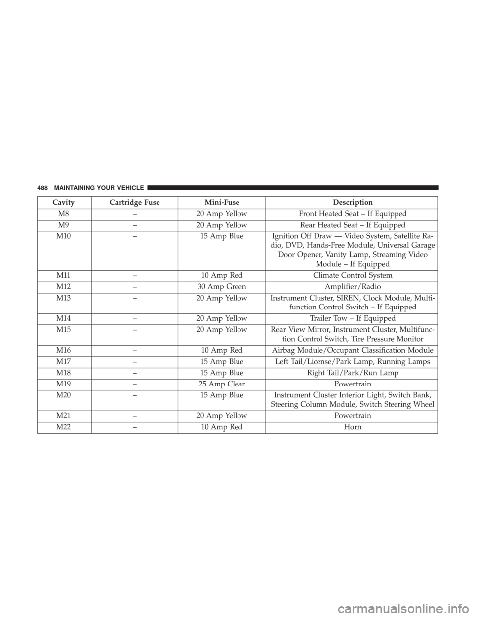
Cavity Cartridge FuseMini-FuseDescription
M8 –20 Amp Yellow Front Heated Seat – If Equipped
M9 –20 Amp Yellow Rear Heated Seat – If Equipped
M10 –15 Amp Blue Ignition Off Draw — Video System, Satellite Ra-
dio, DVD, Hands-Free Module, Universal GarageDoor Opener, Vanity Lamp, Streaming Video Module – If Equipped
M11 –10 Amp Red Climate Control System
M12 –30 Amp Green Amplifier/Radio
M13 –20 Amp Yellow Instrument Cluster, SIREN, Clock Module, Multi-
function Control Switch – If Equipped
M14 –20 Amp Yellow Trailer Tow – If Equipped
M15 –20 Amp Yellow Rear View Mirror, Instrument Cluster, Multifunc-
tion Control Switch, Tire Pressure Monitor
M16 –10 Amp Red Airbag Module/Occupant Classification Module
M17 –15 Amp Blue Left Tail/License/Park Lamp, Running Lamps
M18 –15 Amp Blue Right Tail/Park/Run Lamp
M19 –25 Amp Clear Powertrain
M20 –15 Amp Blue Instrument Cluster Interior Light, Switch Bank,
Steering Column Module, Switch Steering Wheel
M21 –20 Amp Yellow Powertrain
M22 –10 Amp Red Horn
488 MAINTAINING YOUR VEHICLE