Page 308 of 774
306
Number plate lamps
(side-hinged doors)
Ty p e A, W5W-5W
F
R
emove the plastic cover using a small
screwdriver.
F
U
sing a screwdriver through the aperture,
push the lamp towards the outside.
F
D
isconnect the electrical connector.
F
R
emove the lamp.
F
T
urn the bulb holder a quarter turn anti-
clockwise.
F
C
hange the failed bulb.
To refit, press on the lamp to clip it in place.
Third brake lamp
(side-hinged doors)
Ty p e A , W5W-5W
To refit, press on the lens to clip it in place.
F
O
pen the left-hand rear door. F
I
nsert a thin screwdriver into one of the
cut-outs in the lens.
F
P
ush it outwards to unclip it.
F
R
emove the lens.
F
C
hange the failed bulb.
In the event of a breakdown
Page 310 of 774

308
Rear lamps
(tailgate)
For more information on Changing a bulb and
in particular, the types of bulbs, refer to the
corresponding section.
F
W
hile holding the lamp in place, press the
clip on the inside then carefully remove the
lamp.
F
D
isconnect the electrical connector.
F
I
dentify the failed bulb then open the boot.
For vehicles with interior trim, contact
a CITROËN dealer or a qualified
workshop to have the work done.
1.
B
rake lamps / sidelamps.
Ty
p e B, P21/5W-21/5W.
2.
D
irection indicators.
Ty
p e B, PY21W-21W (amber)
3.
R
eversing lamps.
Ty
p e B, P21W-21W
4.
F
oglamps / sidelamps.
Ty
p e B, P21/4W-21/4W. F
F
rom inside, remove the cover, if your
vehicle has one.
F
F
rom the outside, press on the inner clips
on the plastic finisher then tip it towards the
outside to remove it.
F
U
nscrew the two lamp fixing screws.F
S
pread the three lugs slightly, then extract
the bulb holder.
F
R
emove the failed bulb by pressing
lightly on it, then turning it a quarter turn
clockwise.
F
C
hange the bulb.
To reassemble, carry out these operations in
reverse order.
In the event of a breakdown
Page 311 of 774
309
To refit, press on the lens to clip it in place.
F
U
nclip the trim at each end by turning it
upwards.
F
P
ull on the trim to disengage the central
clips, then remove it.
F
U
sing a screwdriver through the aperture,
push the lamp towards the outside.
F
D
isconnect the electrical connector.
F
R
emove the lamp.
F
T
urn the bulb holder a quarter turn anti-
clockwise.
F
C
hange the failed bulb.
To refit, carry out these operations in reverse
o r d e r.
To refit the lamp and trim, press on them to clip
them in place.
Third brake lamp
(tailgate)
Ty p e A , W5W-5W
Number plate lamps
(tailgate)
Ty p e A, W5W-5W
F
O
pen the tailgate. F
I
nsert a thin screwdriver into one of the cut-
outs in the lens.
F
P
ush it outwards to unclip it.
F
R
emove the lens.
F
C
hange the failed bulb.
8
In the event of a breakdown
Page 315 of 774

313
FuseN° Rating
(A) Functions
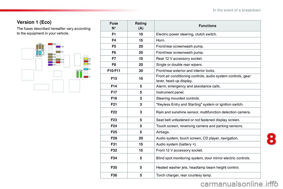
F1 10Electric power steering, clutch switch.
F4 15Horn.
F5 20Front/rear screenwash pump.
F6 20Front/rear screenwash pump.
F7 10Rear 12 V accessory socket.
F8 20Single or double rear wipers.
F10/F11 30Front /rear exterior and interior locks.
F13 10Front air conditioning controls, audio system controls, gear
lever, head-up display.
F14 5Alarm, emergency and assistance calls.
F17 5Instrument panel.
F19 3Steering mounted controls.
F21 3"Keyless Entry and Starting" system or ignition switch.
F22 3Rain and sunshine sensor, multifunction detection camera.
F23 5Seat belt unfastened or not fastened display screen.
F24 5Touch screen, reversing camera and parking sensors.
F25 5Airbags.
F29 20Audio system, touch screen, CD player, navigation.
F31 15Audio system (battery +).
F32 15Front 12 V accessory socket.
F34 5Blind spot monitoring system, door mirror electric controls.
F35 5Heated washer jets, headlamp beam height control.
F36 5Torch charger, rear courtesy lamp.Version 1 (Eco)
The fuses described hereafter vary according
to the equipment in your vehicle.
8
In the event of a breakdown
Page 316 of 774

314
FuseN° Rating
(A) Functions
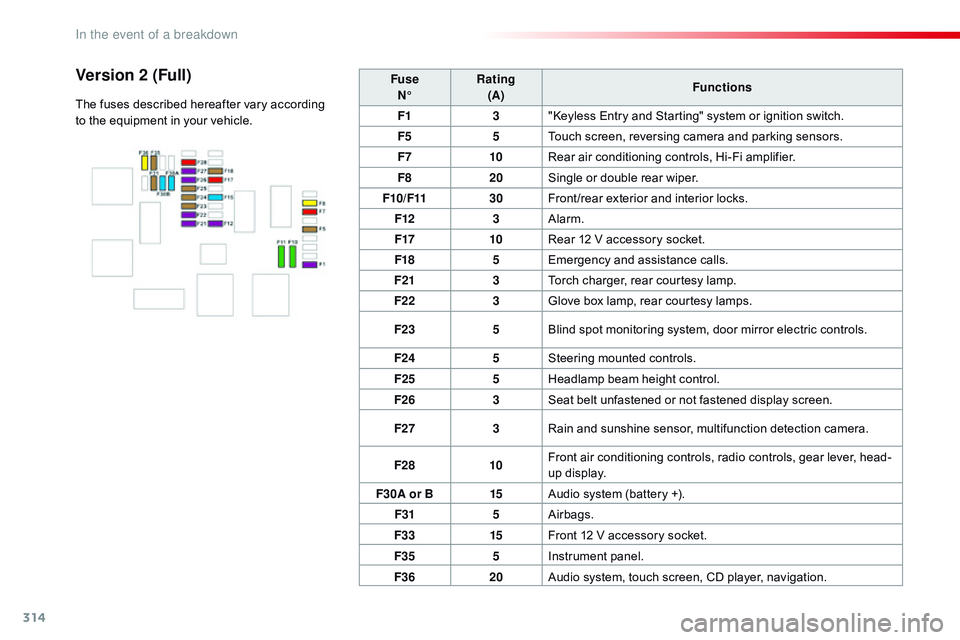
F1 3"Keyless Entry and Starting" system or ignition switch.
F5 5Touch screen, reversing camera and parking sensors.
F7 10Rear air conditioning controls, Hi-Fi amplifier.
F8 20Single or double rear wiper.
F10/F11 30Front /rear exterior and interior locks.
F12 3Alarm.
F17 10Rear 12 V accessory socket.
F18 5Emergency and assistance calls.
F21 3Torch charger, rear courtesy lamp.
F22 3Glove box lamp, rear courtesy lamps.
F23 5Blind spot monitoring system, door mirror electric controls.
F24 5Steering mounted controls.
F25 5Headlamp beam height control.
F26 3Seat belt unfastened or not fastened display screen.
F27 3Rain and sunshine sensor, multifunction detection camera.
F28 10Front air conditioning controls, radio controls, gear lever, head-
up display.
F30A or B 15Audio system (battery +).
F31 5Airbags.
F33 15Front 12 V accessory socket.
F35 5Instrument panel.
F36 20Audio system, touch screen, CD player, navigation.Version 2 (Full)
The fuses described hereafter vary according
to the equipment in your vehicle.
In the event of a breakdown
Page 321 of 774

319
Do not force the lever as locking will
not be possible if the clamp is not
positioned correctly; start the procedure
again.
Disconnecting the battery
In order to maintain an adequate state
of charge for starting the engine, it is
recommended that the battery be disconnected
if the vehicle is taken out of service for a long
period.
Wait 2 minutes after switching off the ignition
before disconnecting the battery.
F
c
lose the windows and the doors before
disconnecting the battery,
F
s
witch off all electrical consumers (audio
system, wipers, lighting, ...),
F
s
witch off the ignition and wait for
four
m
inutes.
Having exposed the battery, it is only
necessary to disconnect the (+) terminal.
Quick release terminal
Disconnecting the (+) terminal
F Raise the lever A fully to release the clamp B.
Following reconnection of the battery
Reconnecting the (+) terminal
F Position the open clamp B of the cable on
the positive post (+) of the battery.
F
P
ress down on the clamp to position it
correctly on the battery post.
F
L
ock the clamp by lowering the lever A .After reconnecting the battery, switch on the
ignition and wait 1 minute before starting to
allow initialisation of the electronic systems.
However, if minor problems persist following
this operation, contact a CITROËN dealer or a
qualified workshop.
Referring to the corresponding section, you
must yourself reinitialise or reset certain
systems, such as:
-
t
he remote control or electronic key
(depending on version),
-
t
he electric windows,
-
t
he date and time,
-
t
he radio preset stations.
The Stop & Start system may not be
operational during the trip following the
first engine start.
In this case, the system will only be
available again after a continuous
period of immobilisation of the vehicle,
a period which depends on the ambient
temperature and the state of charge of
the battery (up to about 8 hours).
8
In the event of a breakdown
Page 323 of 774

321
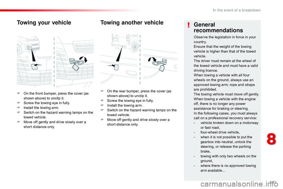
F On the front bumper, press the cover (as shown above) to unclip it.
F
S
crew the towing eye in fully.
F
I
nstall the towing arm.
F
S
witch on the hazard warning lamps on the
towed vehicle.
F
M
ove off gently and drive slowly over a
short distance only.
Towing your vehicle
F On the rear bumper, press the cover (as shown above) to unclip it.
F
S
crew the towing eye in fully.
F
I
nstall the towing arm.
F
S
witch on the hazard warning lamps on the
towed vehicle.
F
M
ove off gently and drive slowly over a
short distance only.
Towing another vehicle General
recommendations
Observe the legislation in force in your
c o unt r y.
Ensure that the weight of the towing
vehicle is higher than that of the towed
vehicle.
The driver must remain at the wheel of
the towed vehicle and must have a valid
driving licence.
When towing a vehicle with all four
wheels on the ground, always use an
approved towing arm; rope and straps
are prohibited.
The towing vehicle must move off gently.
When towing a vehicle with the engine
off, there is no longer any power
assistance for braking or steering.
In the following cases, you must always
call on a professional recovery service:
-
v
ehicle broken down on a motor way
or fast road,
-
f
our-wheel drive vehicle,
-
w
hen it is not possible to put the
gearbox into neutral, unlock the
steering, or release the parking
brake,
-
t
owing with only two wheels on the
ground,
-
w
here there is no approved towing
arm available...
8
In the event of a breakdown
Page 368 of 774

366
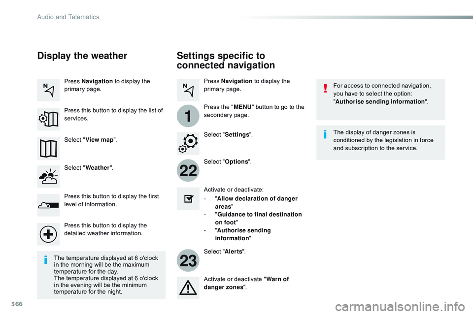
22
23
1
Settings specific to
connected navigation
For access to connected navigation,
you have to select the option:
"Authorise sending information ".
Select " Options ".
Select " Alerts".
-
" A
llow declaration of danger
areas "
-
" G
uidance to final destination
on foot "
-
" A
uthorise sending
information "
Activate or deactivate:
Activate or deactivate "
Warn of
danger zones ". The display of danger zones is
conditioned by the legislation in force
and subscription to the service.
The temperature displayed at 6 o'clock
in the morning will be the maximum
temperature for the day.
The temperature displayed at 6 o'clock
in the evening will be the minimum
temperature for the night. Select "
Settings ".
Press
Navigation to display the
primary page.
Press the " MENU" button to go to the
secondary page.
Display the weather
Select " Weather ".
Press this button to display the first
level of information.
Press this button to display the
detailed weather information. Select " View map ".
Press Navigation
to display the
primary page.
Press this button to display the list of
services.
Audio and Telematics