Page 581 of 828

9. Inflate the tire to 60 psi (4.2 Bar)recommended as per the label on
the wheel or if the vehicle equipped
with the inflatable spare tire pres-
sure indicated on the Tire and
Loading information label located
on the driver-side door opening.
NOTE: If the tire is over inflated, use the deflation button
to reduce the tire air pressure.
10. After the tire reaches the recom-mended pressure, lower the ve-
hicle with the jack as described in
the Jack Instructions section in this
manual. 11. Remove the speed limit label
sticker from the Tire Service Kit
and place it on the center of the
steering wheel.
12. Return the Tire Service Kit to the foam tray and secure it with the strap. Store the foam tray in the
cargo area.
Road Tire Installation
Vehicles Equipped With Wheel Covers
1. Mount the road tire on the axle.
2. To ease the installation process for steel wheels withwheel covers, install two lug nuts on the mounting
studs which are on each side of the valve stem. Install
7
IN CASE OF EMERGENCY 579
Page 593 of 828
If the tire inflates to the recommended pressure or is at
least 26 psi (1.8 Bar) pressure within 15 minutes:
NOTE:If the tire becomes over-inflated, push the Defla-
tion Button to reduce the tire pressure to the recom-
mended inflation pressure before continuing.
1. Push the Power Button to turn offthe Tire Service Kit. 2. Remove the speed limit label from
the Tire Service Kit and place
sticker on the steering wheel.
3. Immediately disconnect the Sealant Hose from the valve stem, reinstall the cap on the fitting at the end of
the hose, and place the Tire Service Kit in the vehicle
storage location. Proceed to “Drive Vehicle.”
7
IN CASE OF EMERGENCY 591
Page 596 of 828

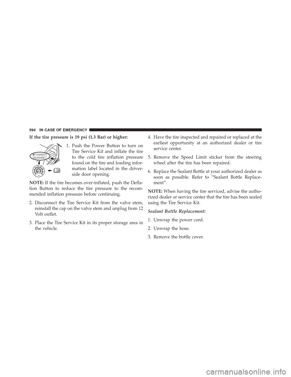
If the tire pressure is 19 psi (1.3 Bar) or higher:1. Push the Power Button to turn onTire Service Kit and inflate the tire
to the cold tire inflation pressure
found on the tire and loading infor-
mation label located in the driver-
side door opening.
NOTE: If the tire becomes over-inflated, push the Defla-
tion Button to reduce the tire pressure to the recom-
mended inflation pressure before continuing.
2. Disconnect the Tire Service Kit from the valve stem, reinstall the cap on the valve stem and unplug from 12
Volt outlet.
3. Place the Tire Service Kit in its proper storage area in the vehicle. 4. Have the tire inspected and repaired or replaced at the
earliest opportunity at an authorized dealer or tire
service center.
5. Remove the Speed Limit sticker from the steering wheel after the tire has been repaired.
6. Replace the Sealant Bottle at your authorized dealer as soon as possible. Refer to “Sealant Bottle Replace-
ment”.
NOTE: When having the tire serviced, advise the autho-
rized dealer or service center that the tire has been sealed
using the Tire Service Kit.
Sealant Bottle Replacement:
1. Unwrap the power cord.
2. Unwrap the hose.
3. Remove the bottle cover.
594 IN CASE OF EMERGENCY
Page 605 of 828

To Reset The Manual Park Release:
1. Pull the tether strap out again, then release it.
2. Allow the tether to retract with the lever back to itsoriginal position.
3. Verify that the transmission is in PARK.
4. Confirm that the tether has retracted fully and re- install the access cover. If the access cover cannot be
re-installed, repeat steps 1 through 3.
FREEING A STUCK VEHICLE
If your vehicle becomes stuck in mud, sand or snow, it
can often be moved using a rocking motion. Turn the
steering wheel right and left to clear the area around the
front wheels. Then shift back and forth between DRIVE
and REVERSE while gently pressing the accelerator. NOTE:
Shifts between DRIVE and REVERSE can only be
achieved at wheel speeds of 5 mph (8 km/h) or less.
Whenever the transmission remains in NEUTRAL for
more than two seconds, you must press the brake pedal
to engage DRIVE or REVERSE.
Use the least amount of accelerator pedal pressure that
will maintain the rocking motion without spinning the
wheels or racing the engine.
NOTE: Push the �ESC Off� switch to place the Electronic
Stability Control (ESC) system in �Partial Off�mode,
before rocking the vehicle. Refer to “Electronic Brake
Control” in “Safety” for further information. Once the
vehicle has been freed, push the �ESC Off�switch again to
restore �ESC On� mode.
7
IN CASE OF EMERGENCY 603
Page 658 of 828

wear and correct cold tire inflation pressures. The manu-
facturer strongly recommends that you use tires equiva-
lent to the originals in size, quality and performance
when replacement is needed. Refer to the paragraph on
“Tread Wear Indicator”. Refer to the Tire and Loading
Information placard or the Vehicle Certification Label for
the size designation of your tire. The Load Index and
Speed Symbol for your tire will be found on the original
equipment tire sidewall. See the Tire Sizing Chart ex-
ample found in the “Tire Safety Information” section of
this manual for more information relating to the Load
Index and Speed Symbol of a tire.
It is recommended to replace the two front tires or two
rear tires as a pair. Replacing just one tire can seriously
affect your vehicle’s handling. If you ever replace a
wheel, make sure that the wheel’s specifications match
those of the original wheels.It is recommended you contact your authorized tire
dealer or original equipment dealer with any questions
you may have on tire specifications or capability. Failure
to use equivalent replacement tires may adversely affect
the safety, handling, and ride of your vehicle.
WARNING!
•
Do not use a tire, wheel size, load rating, or speed
rating other than that specified for your vehicle.
Some combinations of unapproved tires and
wheels may change suspension dimensions and
performance characteristics, resulting in changes to
steering, handling, and braking of your vehicle.
This can cause unpredictable handling and stress
to steering and suspension components. You could
(Continued)
656 MAINTAINING AND CARING FOR YOUR VEHICLE
Page 693 of 828
MULTIMEDIA
CONTENTS
�UCONNECT RADIOS ...................694
� PERSONALIZED MENU BAR ..............694
� CYBERSECURITY ...................... .695
� UCONNECT SETTINGS ..................696
▫ Customer Programmable Features — Uconnect 5.0
Settings ........................... .697
▫ Customer Programmable Features — Uconnect 8.4
Settings ............................ .718
� STEERING WHEEL AUDIO CONTROLS ......742
▫ Radio Operation ..................... .743�
AUX/USB/MP3 CONTROL ...............743
� UCONNECT THEATER — IF EQUIPPED .....745
▫ Getting Started ...................... .746
▫ Accessing The System From The Uconnect
Radio ............................. .747
▫ Uconnect Theater Controls ...............748
▫ Accessing The System From The Uconnect Theater
Rear Screens ........................ .749
▫ Pairing The Remote ....................750
▫ Unpairing The Remote ..................751
10
Page 706 of 828

8 mph (13 km/h), the transmission is shifted into PARK
or the ignition is switched to the OFF position.
•ParkView Backup Camera Delay — If Equipped
Press the “Parkview Backup camera Delay” button
on the touchscreen to turn the ParkView Delay ON or
OFF.
• ParkView Backup Camera Active Guide Lines — If
Equipped When this feature is enabled, active (dynamic) grid
lines are overlaid on the Rear Backup Camera image
to illustrate the width of the vehicle and its projected
back up path based on the steering wheel position. A
dashed center line overlay indicates the center of the
vehicle to assist with parking or aligning to a hitch/
receiver.
• Forward Collision Warning On/Off — If Equipped
The default status of FCW is “On”, this allows the system
to warn you of a possible collision with the vehicle in front of you. The forward collision button is located in
the Uconnect display in the controls settings. To turn the
FCW system OFF, push the forward collision button once
to turn the system OFF. To turn the FCW system back
ON, push the forward collision button again to turn the
system ON. Changing the FCW status to “OFF” prevents
the system from warning you of a possible collision with
the vehicle in front of you.
•
Forward Collision Warning-Plus (FCW+) — If
Equipped
The Front Collision Warning (FCW+) feature can be can
be set to Far, Med or Near. The default status of FCW+ is
the Med setting. This means the system will warn you of
a possible collision with the vehicle in front of you when
you are a relatively medium distance away. This gives
you the medium reaction time. To change the setting for
a more dynamic driving experience, select the Near
setting. This warns you of a possible collision when you
704 MULTIMEDIA
Page 708 of 828

•LaneSense Warning — If Equipped
When this feature is selected, it sets the distance at which
the steering wheel will provide feedback for potential
lane departures. The LDW sensitivity can be set to
provide either an “early,” “medium,” or “late” warning
zone start point. The default setting is “Medium”.
• LaneSense Strength — If Equipped
When this feature is selected, it sets the strength of the
steering wheel feedback for potential lane departures.
The amount of directional torque the steering system can
apply to the steering wheel to correct for vehicle lane
departure can be set at “Low,” “Medium” or “High.” The
default setting is “Medium”.
• Blind Spot Alert — If Equipped
When this feature is selected, the Blind Spot Alert feature
can be set to Off, Lights or Lights and Chime. The Blind
Spot Alert feature can be activated in Lights mode. When this mode is selected, the Blind Spot Monitor (BSM)
system is activated and will only show a visual alert in
the outside mirrors. When Lights & Chime mode is
activated, the Blind Spot Monitor (BSM) will show a
visual alert in the outside mirrors as well as an audible
alert when the turn signal is on. When Off is selected, the
Blind Spot Monitor (BSM) system is deactivated. To
change the Blind Spot Alert status, press the “Off,”
“Lights” or “Lights & Chime” button on the touchscreen.
Then press the back arrow button on the touchscreen.
The default setting is “Lights”
NOTE:
If your vehicle has experienced any damage in
the area where the sensor is located, even if the fascia is
not damaged, the sensor may have become misaligned.
Take your vehicle to an authorized dealer to verify sensor
alignment. A sensor that is misaligned will result in the
BSM not operating to specification.
706 MULTIMEDIA