2017 BMW 6 SERIES GRAN COUPE lights
[x] Cancel search: lightsPage 168 of 261
Preselecting the switch-on time
On the Control Display:1."Settings"2."Climate"3."Timer 1:" or "Timer 2:"4.Set the desired time.
Activating the activation time On the Control Display:
1."Settings"2."Climate"3."Activate timer 1" or "Activate timer 2"
The symbol on the automatic climate con‐
trol lights up when the switch-on time is acti‐
vated.
The symbol on the automatic climate con‐
trol flashes when the system has been
switched on.
The system will only be switched on within the
next 24 hours. After that, it needs to be reacti‐
vated.
Seite 168ControlsClimate control168
Online Edition for Part no. 01 40 2 969 305 - II/16
Page 174 of 261
▷MTP devices.▷Devices such as fans or lights.
Overview
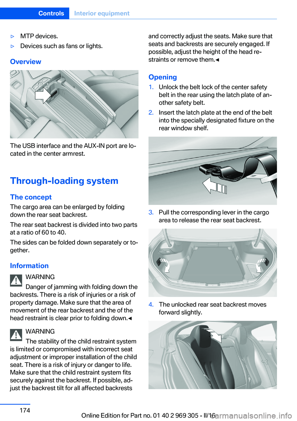
The USB interface and the AUX-IN port are lo‐
cated in the center armrest.
Through-loading system The concept The cargo area can be enlarged by folding
down the rear seat backrest.
The rear seat backrest is divided into two parts
at a ratio of 60 to 40.
The sides can be folded down separately or to‐
gether.
Information WARNING
Danger of jamming with folding down the
backrests. There is a risk of injuries or a risk of
property damage. Make sure that the area of
movement of the rear backrest and the of the
head restraint is clear prior to folding down.◀
WARNING
The stability of the child restraint system
is limited or compromised with incorrect seat
adjustment or improper installation of the child
seat. There is a risk of injury or danger to life.
Make sure that the child restraint system fits
securely against the backrest. If possible, ad‐
just the backrest tilt for all affected backrests
and correctly adjust the seats. Make sure that
seats and backrests are securely engaged. If
possible, adjust the height of the head re‐
straints or remove them.◀
Opening1.Unlock the belt lock of the center safety
belt in the rear using the latch plate of an‐
other safety belt.2.Insert the latch plate at the end of the belt
into the specially designated fixture on the
rear window shelf.3.Pull the corresponding lever in the cargo
area to release the rear seat backrest.4.The unlocked rear seat backrest moves
forward slightly.Seite 174ControlsInterior equipment174
Online Edition for Part no. 01 40 2 969 305 - II/16
Page 191 of 261
Use coastingWhen approaching a red light, take your foot
off the accelerator and let the vehicle coast to
a halt.
For going downhill take your foot off the accel‐
erator and let the vehicle roll.
The flow of fuel is interrupted while coasting.
Switch off the engine during
longer stops
Switch off the engine during longer stops, for example, at traffic lights, railroad crossings or
in traffic congestion.
Auto Start/Stop function The Auto Start/Stop function of the vehicle au‐
tomatically switches off the engine during a
stop.
If the engine is switched off and then restarted
rather than leaving the engine running con‐
stantly, fuel consumption and emissions are
reduced. Savings can begin within a few sec‐
onds of switching off the engine.
In addition, fuel consumption is also deter‐
mined by other factors, such as driving style,
road conditions, maintenance or environmental
factors.
Switch off any functions that
are not currently needed
Functions such as seat heating and the rear
window defroster require a lot of energy and
reduce the range, especially in city and stop-
and-go traffic.
Switch off these functions if they are not
needed.
The ECO PRO driving program supports the
energy conserving use of comfort features.
These functions are automatically deactivated
partially or completely.Have maintenance carried
out
Have vehicles maintained regularly to achieve
optimal vehicle efficiency and service life.
BMW recommends that maintenance work be
performed by a BMW dealer’s service center.
For information on the BMW Maintenance
System, refer to page 226.
ECO PRO
The concept ECO PRO supports a driving style that saves
on fuel consumption. For this purpose, the en‐
gine control and comfort features, e.g. the cli‐
mate control output, are adjusted.
Under certain conditions the engine is auto‐
matically decoupled from the transmission in
the D selector lever position. The vehicle con‐
tinues traveling with the engine idling to re‐
duce fuel consumption. Selector lever position
D remains engaged.
In addition, context-sensitive instructions are
displayed to assist with an optimized fuel con‐
sumption driving style.
The achieved extended range is displayed in
the instrument cluster as bonus range.
Overview
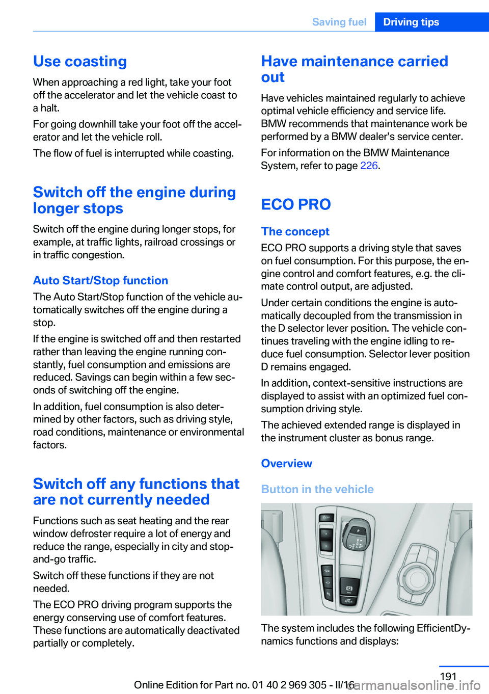
Button in the vehicle
The system includes the following EfficientDy‐
namics functions and displays:
Seite 191Saving fuelDriving tips191
Online Edition for Part no. 01 40 2 969 305 - II/16
Page 227 of 261
Socket for OBD Onboard
Diagnosis
Information ATTENTION
The socket for Onboard Diagnosis is an
intricate component intended to be used in
conjunction with specialized equipment to
check the vehicle’s primary emissions system.
Improper use of the socket for Onboard Diag‐
nosis, or contact with the socket for Onboard
Diagnosis for other than its intended purpose,
can cause vehicle malfunctions and creates
risks of personal and property damage. Given
the foregoing, the manufacture of your vehicle
strongly recommends that access to the
socket for Onboard Diagnosis be limited to a
dealer's service center or another qualified
service center or repair shop or other persons
that have the specialized training and equip‐
ment for purposes of properly utilizing the
socket for Onboard Diagnosis.◀
Position
There is an OBD socket on the driver's side for
checking the primary components in the vehi‐
cle's emissions.
Emissions
▷The warning lamp lights up:
Emissions are deteriorating. Have
the vehicle checked as soon as
possible.▷The warning lamp flashes under certain
circumstances:
This indicates that there is excessive mis‐
firing in the engine.
Reduce the vehicle speed and have the
system checked immediately; otherwise,
serious engine misfiring within a brief pe‐
riod can seriously damage emission con‐
trol components, in particular the catalytic
converter.Seite 227MaintenanceMobility227
Online Edition for Part no. 01 40 2 969 305 - II/16
Page 228 of 261
Replacing componentsVehicle features and optionsThis chapter describes all standard, country-
specific and optional features offered with the
series. It also describes features that are not
necessarily available in your car, e. g., due to
the selected options or country versions. This
also applies to safety-related functions and
systems. The respectively applicable country
provisions must be observed when using the
respective features and systems.
Onboard vehicle tool kit
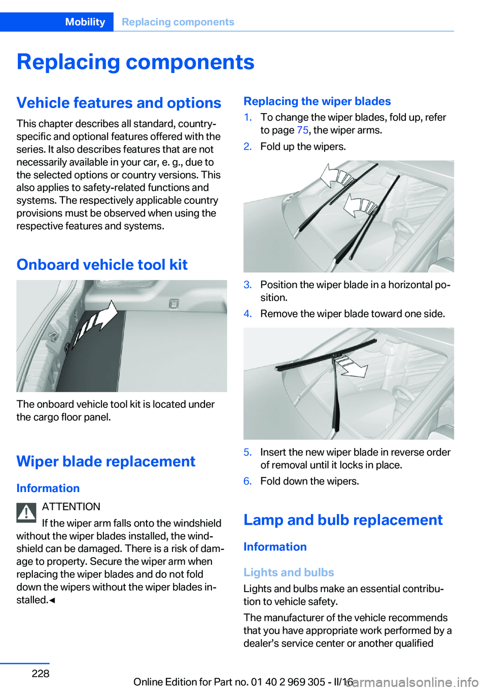
The onboard vehicle tool kit is located under
the cargo floor panel.
Wiper blade replacement Information ATTENTION
If the wiper arm falls onto the windshield
without the wiper blades installed, the wind‐
shield can be damaged. There is a risk of dam‐
age to property. Secure the wiper arm when
replacing the wiper blades and do not fold
down the wipers without the wiper blades in‐
stalled.◀
Replacing the wiper blades1.To change the wiper blades, fold up, refer
to page 75, the wiper arms.2.Fold up the wipers.3.Position the wiper blade in a horizontal po‐
sition.4.Remove the wiper blade toward one side.5.Insert the new wiper blade in reverse order
of removal until it locks in place.6.Fold down the wipers.
Lamp and bulb replacement
Information
Lights and bulbs
Lights and bulbs make an essential contribu‐
tion to vehicle safety.
The manufacturer of the vehicle recommends
that you have appropriate work performed by a
dealer’s service center or another qualified
Seite 228MobilityReplacing components228
Online Edition for Part no. 01 40 2 969 305 - II/16
Page 229 of 261
service center or repair shop if you are unfami‐
liar with it or if it has not been described here.
A spare lamp box is available from a dealer’s
service center or another qualified service cen‐
ter or repair shop.
WARNING
Bulbs can get hot during operation. Con‐
tact with the bulbs can cause burns. There is a
risk of injuries. Only change bulbs after they
have cooled off.◀
WARNING
Work on switched-on lighting systems
can cause short circuits. There is a risk of inju‐
ries or a risk of property damage. When work‐
ing on the lighting system, switch off the lamps
in question. If necessary, heed the bulb manu‐
facturer's instructions.◀
CAUTION
Dirty bulbs have a reduced service life.
There is a risk of property damage. Do not hold
new bulbs with your bare hands. Use a clean
cloth or something similar, or hold the bulb by
its base.◀
Light-emitting diodes (LEDs)
Some items of equipment use light-emitting
diodes installed behind a cover as a light
source.
These light-emitting diodes, which are related
to conventional lasers, are officially designated as Class 1 light-emitting diodes.
WARNING
Too intensive brightness can irritate or
damage the retina of the eye. There is a a risk
of injury. Do not look directly into the head‐
lights or other light sources. Do not remove the LED covers.◀
Headlight glass
Condensation can form on the inside of the ex‐
ternal lights in cool or humid weather. Whendriving with the lights switched on, the con‐
densation evaporates after a short time. The
headlight glass does not need to be changed.
If despite driving with the lights switched on,
increasing humidity forms, e. g. water droplets
in the lamp, the manufacturer of your vehicle
recommends having it checked by a dealer’s
service center or another qualified service cen‐
ter or repair shop.
Headlight setting
The headlight adjustments can be affected by
changing lights and bulbs. After the headlight
adjustment was changed, have it checked and,
if necessary, corrected by a dealer’s service
center or another qualified service center or re‐ pair shop.
Front lights, bulb replacement
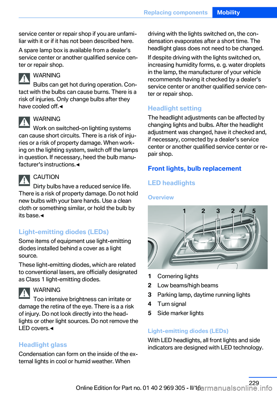
LED headlights Overview1Cornering lights2Low beams/high beams3Parking lamp, daytime running lights4Turn signal5Side marker lights
Light-emitting diodes (LEDs)
With LED headlights, all front lights and side
indicators are designed with LED technology.
Seite 229Replacing componentsMobility229
Online Edition for Part no. 01 40 2 969 305 - II/16
Page 230 of 261

If an LED fails, switch on the front fog lamps
and continue the trip with great care. Comply
with local regulations.
In the case of a malfunction, contact a dealer’s
service center or another qualified service cen‐
ter or repair shop.
LED front fog lights
These front fog lights are made using LED
technology. In the case of a malfunction, con‐
tact a dealer’s service center or another quali‐
fied service center or repair shop.
Turn signal in exterior mirror
The turn signals in the exterior mirrors feature
LED technology. In the case of a malfunction,
contact a dealer’s service center or another
qualified service center or repair shop.
Tail lamps, bulb replacement
Overview1Turn signal/brake lamp2Reversing lamp3Inside brake lamp4Rear lamp5Outside brake lamp6Rear reflector
Turn signal, outer brake, tail, and
license plate lights
Follow general instructions, refer to page 228.
These lights feature LED technology.
In the case of a malfunction, contact a dealer’s
service center or another qualified service cen‐
ter or repair shop.
Lights in the tailgate
Access to the lights
If necessary, remove the fasteners using the
screwdriver from the onboard vehicle tool kit
and fold away the cover.
Inside brake lamp
Follow general instructions, refer to page 228.
24-watt bulb, HP24W.
1.Squeeze the bulb holder and pull it out.2.Pull off the connector.3.Replace the bulb.4.Mount the bulb holder and the cover of the
tailgate in reverse order.
Reversing lamp
Follow general instructions, refer to page 228.
Seite 230MobilityReplacing components230
Online Edition for Part no. 01 40 2 969 305 - II/16
Page 233 of 261
Breakdown assistanceVehicle features and options
This chapter describes all standard, country-
specific and optional features offered with the
series. It also describes features that are not
necessarily available in your car, e. g., due to
the selected options or country versions. This
also applies to safety-related functions and
systems. The respectively applicable country
provisions must be observed when using the
respective features and systems.
Hazard warning flashers
The button is located in the center console.
Intelligent emergency call
The concept In case of an emergency, an Emergency Re‐
quest can be made through this system.
General information
Only press the SOS button in an emergency.
For technical reasons, the Emergency Request
cannot be guaranteed under unfavorable con‐
ditions.
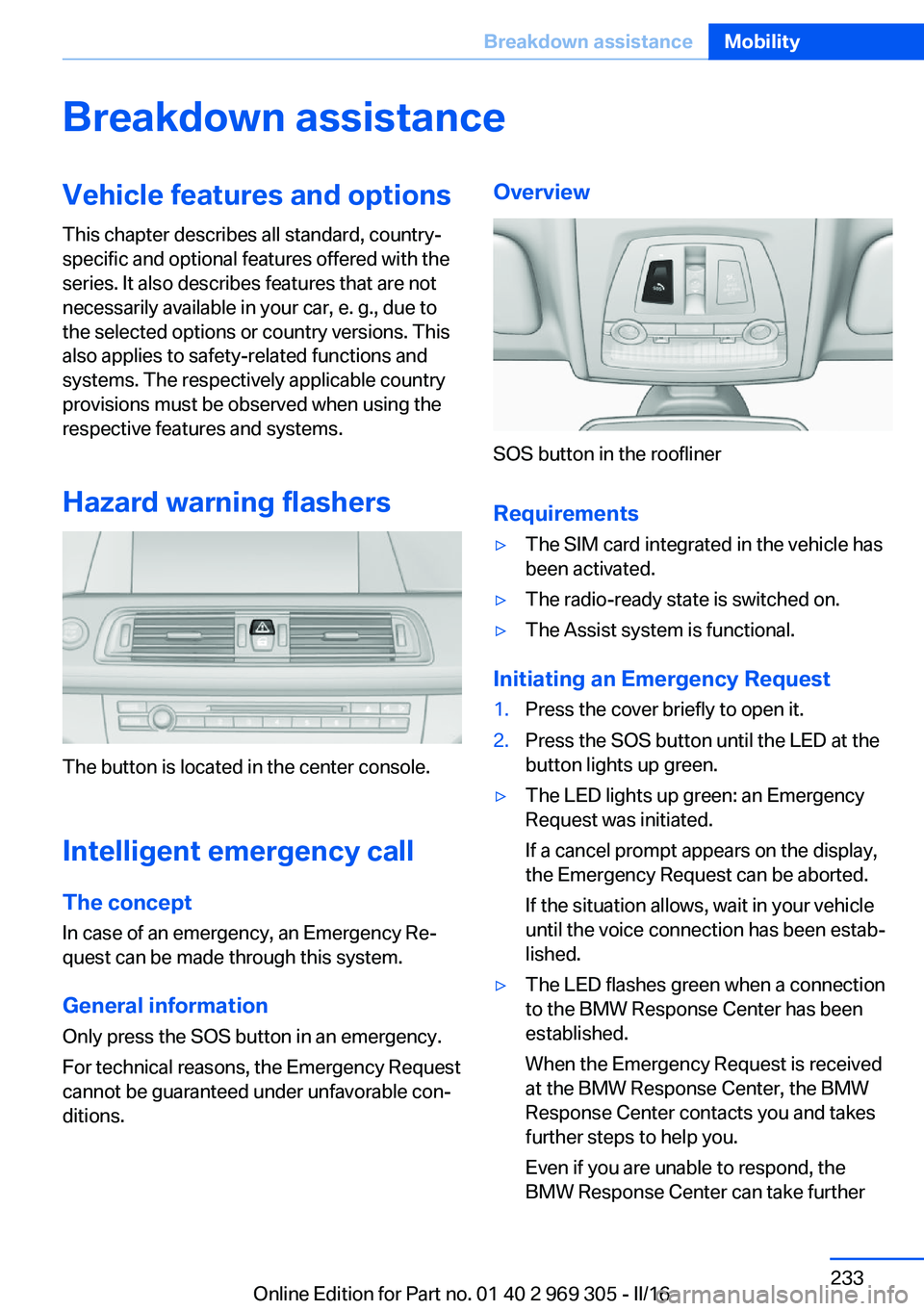
Overview
SOS button in the roofliner
Requirements
▷The SIM card integrated in the vehicle has
been activated.▷The radio-ready state is switched on.▷The Assist system is functional.
Initiating an Emergency Request
1.Press the cover briefly to open it.2.Press the SOS button until the LED at the
button lights up green.▷The LED lights up green: an Emergency
Request was initiated.
If a cancel prompt appears on the display,
the Emergency Request can be aborted.
If the situation allows, wait in your vehicle
until the voice connection has been estab‐
lished.▷The LED flashes green when a connection
to the BMW Response Center has been
established.
When the Emergency Request is received
at the BMW Response Center, the BMW
Response Center contacts you and takes
further steps to help you.
Even if you are unable to respond, the
BMW Response Center can take furtherSeite 233Breakdown assistanceMobility233
Online Edition for Part no. 01 40 2 969 305 - II/16