Page 247 of 356
OIL PUMP AND BALANCER GEAR
5-54
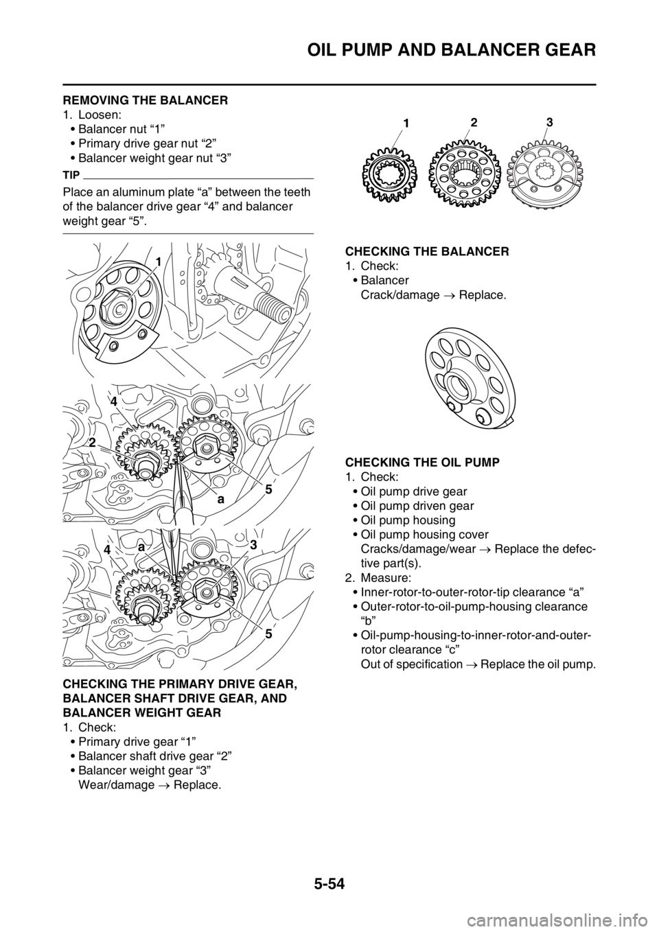
EAS1SM9264REMOVING THE BALANCER
1. Loosen:
• Balancer nut “1”
• Primary drive gear nut “2”
• Balancer weight gear nut “3”
TIP
Place an aluminum plate “a” between the teeth
of the balancer drive gear “4” and balancer
weight gear “5”.
EAS1SM9265CHECKING THE PRIMARY DRIVE GEAR,
BALANCER SHAFT DRIVE GEAR, AND
BALANCER WEIGHT GEAR
1. Check:
• Primary drive gear “1”
• Balancer shaft drive gear “2”
• Balancer weight gear “3”
Wear/damage Replace.
EAS1SM9266CHECKING THE BALANCER
1. Check:
•Balancer
Crack/damage Replace.
EAS1SM9267CHECKING THE OIL PUMP
1. Check:
• Oil pump drive gear
• Oil pump driven gear
• Oil pump housing
• Oil pump housing cover
Cracks/damage/wear Replace the defec-
tive part(s).
2. Measure:
• Inner-rotor-to-outer-rotor-tip clearance “a”
• Outer-rotor-to-oil-pump-housing clearance
“b”
• Oil-pump-housing-to-inner-rotor-and-outer-
rotor clearance “c”
Out of specification Replace the oil pump.
1
4
a5
2
4a
5
3
Page 248 of 356

OIL PUMP AND BALANCER GEAR
5-55
3. Check:
• Oil pump operation
Rough movement Repeat steps (1) and
(2) or replace the defective part(s).
EAS1SM9268ASSEMBLING THE OIL PUMP
1. Install:
• Oil pump drive shaft “1”
• Inner rotor “2”
• Dowel pin “3”
TIP
• Apply the engine oil on the oil pump drive
shaft and inner rotor.• Fit the dowel pin into the groove in the inner
rotor.
2. Install:
• Outer rotor “1”
TIP
Apply the engine oil on the outer rotor.
3. Install:
• Oil pump cover “1”
• Oil pump cover screw “2”
EAS1SM9269INSTALLING THE OIL PUMP AND BALANC-
ER GEAR
1. Install:
• Oil pump assembly “1”
• Oil pump assembly bolt “2” Inner-rotor-to-outer-rotor-tip
clearance
Less than
0.150 mm (0.0059 in)
Limit
0.20 mm (0.0079 in)
Outer-rotor-to-oil-pump-housing
clearance
0.13–0.18 mm (0.0051–0.0071 in)
Limit
0.24 mm (0.0094 in)
Oil-pump-housing-to-inner-and-
outer-rotor clearance
0.06–0.11 mm (0.0024–0.0043 in)
Limit
0.17 mm (0.0067 in)
1. Inner rotor
2. Outer rotor
3. Oil pump housing
b
a 1
2
3
c
Oil pump cover screw
2.0 Nm (0.20 m·kgf, 1.4 ft·lbf)
Oil pump assembly bolt
5 Nm (0.5 m·kgf, 3.6 ft·lbf)
LOCTITE®
21
3
1
E
T R..
2
1
T R..
Page 257 of 356

CRANKCASE
5-64
EAS1SM9276DISASSEMBLING THE CRANKCASE
1. Separate:
• Right crankcase
• Left crankcase
▼▼▼▼▼▼▼▼▼▼▼▼▼▼▼▼▼▼▼▼▼▼▼▼▼▼▼▼▼▼▼▼
a. Remove the crankcase bolts.
TIP
Loosen each bolt 1/4 of a turn at a time and af-
ter all the bolts are loosened, remove them.
b. Remove the right crankcase “1”.
TIP
• Place the crankcase with its left side down-
ward and split it by inserting a screwdriver tip
into the splitting slit “a” in the crankcase.
• Lift the right crankcase horizontally while light-
ly patting the crankcase splitting slit and the
engine mounting boss using a soft hammer,
and leave the crankshaft and the transmission
with the left crankcase.
ECA
NOTICE
Use soft hammer to tap on the case half.
Tap only on reinforced portions of case. Do
not tap on gasket mating surface. Work
slowly and carefully. Make sure the case
halves separate evenly. If the cases do not
separate, check for a remaining case bolt or
fitting. Do not force.c. Remove the dowel pins and O-ring.
▲▲▲▲▲▲▲▲▲▲▲▲▲▲▲▲▲▲▲▲▲▲▲▲▲▲▲▲▲▲▲▲EAS1SM9277REMOVING THE CRANKCASE BEARING
1. Remove:
• Bearing “1”
TIP
• Remove the bearing from the crankcase by
pressing its inner race.
• Do not use the removed bearing.
EAS1SM9278CHECKING THE TIMING CHAIN, TIMING
CHAIN GUIDE, OIL STRAINER
1. Check:
• Timing chain
Stiffness Replace the camshaft sprocket,
timing chain and crankshaft sprocket as a
set.
2. Check:
• Timing chain guide
Damage/wear Replace
EAS1SM9279CHECKING THE CRANKCASE
1. Wash:
• Crankcase
TIP
• Wash the crankcase in a mild solvent.
• Remove any remaining gasket from the
crankcase mating surface.
2. Check:
• Crankcase
Crack/damage Replace.
• Oil delivery passages
Obstruction Blow out with compressed
air.
1
a
Page 260 of 356
CRANKSHAFT ASSEMBLY AND BALANCER SHAFT
5-67
EAS1SM9283REMOVING THE CRANKSHAFT ASSEMBLY
1. Remove:
• Crankshaft assembly “1”
TIP
Remove the crankshaft assembly by using the
crankcase separating tool “2”.
EAS1SM9284CHECKING THE CRANKSHAFT ASSEMBLY
1. Measure:
• Crankshaft runout
Out of specification Replace the crank-
shaft, bearing or both.
TIP
Turn the crankshaft slowly.2. Measure:
• Big end side clearance “a”
Out of specification Replace the big end
bearing, crankshaft pin, or connecting rod.
3. Measure:
• Crank assembly width “a”
Out of specification Replace the crank-
shaft.
4. Check:
• Crankshaft sprocket “1”
Damage Replace the crankshaft.
5. Check:
• Crankshaft journal oil passage
Obstruction Blow out with compressed
air. Crankcase separating tool
90890-04152
YU-A9642
Runout limit
0.030 mm (0.0012 in)
2
1
Big end side clearance
0.110–0.690 mm (0.0043–0.0272
in)
Crank assembly width
55.95–56.00 mm (2.203–2.205 in)
1
Page 264 of 356
TRANSMISSION
5-71
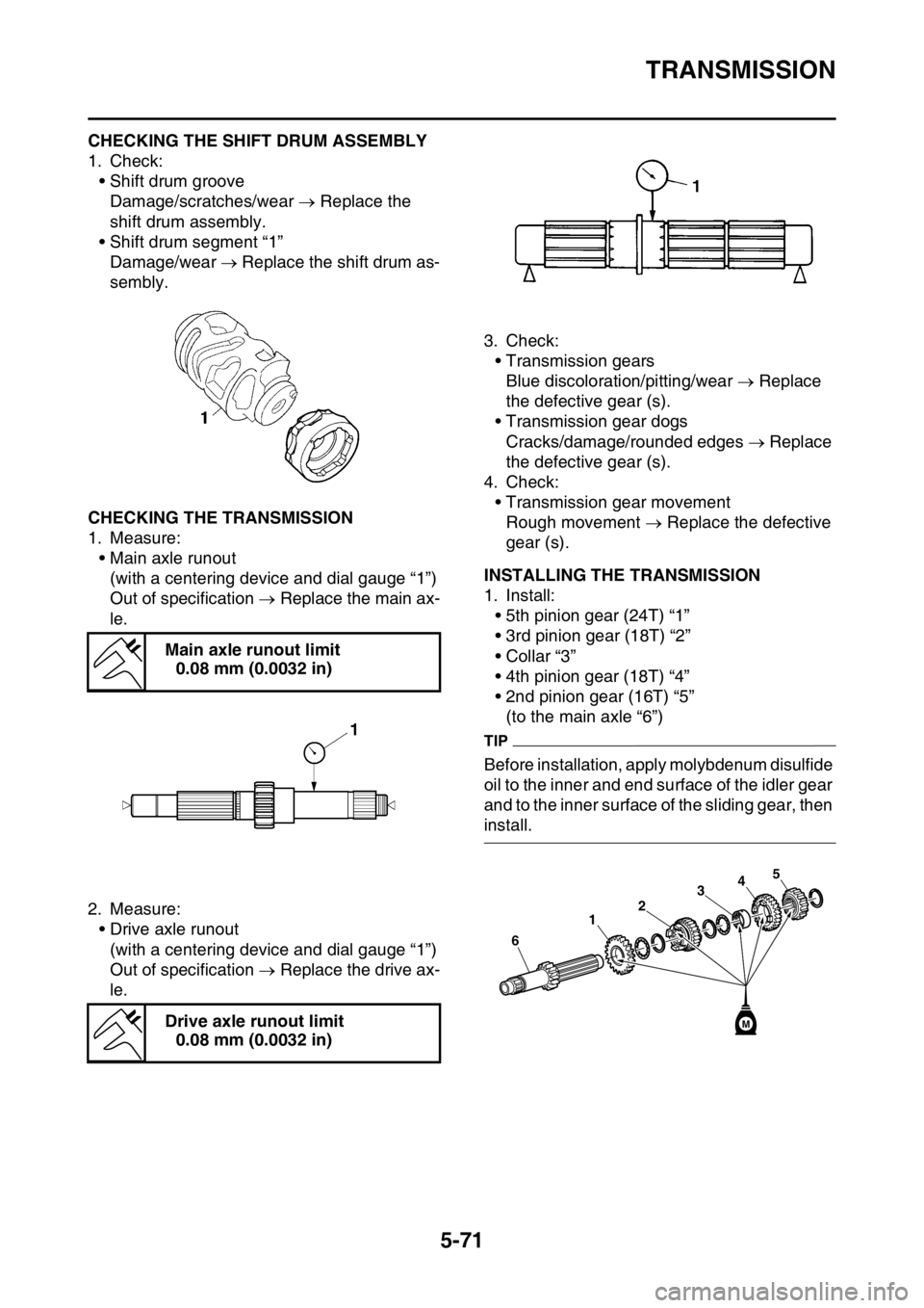
EAS1SM9290CHECKING THE SHIFT DRUM ASSEMBLY
1. Check:
• Shift drum groove
Damage/scratches/wear Replace the
shift drum assembly.
• Shift drum segment “1”
Damage/wear Replace the shift drum as-
sembly.
EAS1SM9291CHECKING THE TRANSMISSION
1. Measure:
• Main axle runout
(with a centering device and dial gauge “1”)
Out of specification Replace the main ax-
le.
2. Measure:
• Drive axle runout
(with a centering device and dial gauge “1”)
Out of specification Replace the drive ax-
le.3. Check:
• Transmission gears
Blue discoloration/pitting/wear Replace
the defective gear (s).
• Transmission gear dogs
Cracks/damage/rounded edges Replace
the defective gear (s).
4. Check:
• Transmission gear movement
Rough movement Replace the defective
gear (s).
EAS1SM9292INSTALLING THE TRANSMISSION
1. Install:
• 5th pinion gear (24T) “1”
• 3rd pinion gear (18T) “2”
• Collar “3”
• 4th pinion gear (18T) “4”
• 2nd pinion gear (16T) “5”
(to the main axle “6”)
TIP
Before installation, apply molybdenum disulfide
oil to the inner and end surface of the idler gear
and to the inner surface of the sliding gear, then
install. Main axle runout limit
0.08 mm (0.0032 in)
Drive axle runout limit
0.08 mm (0.0032 in)
34
2
1
6
5
M
Page 266 of 356
TRANSMISSION
5-73
6. Install:
• Shift fork 1 (L) “1”
• Shift fork 2 (C) “2”
• Shift fork 3 (R) “3”
• Shift cam “4”
(to the main axle and the drive axle)
TIP
• Apply engine oil to the shift fork grooves.
• Apply engine oil to the shift cam groove and
the bearing contact surface.
• Mesh the shift fork 1 (L) with the 4th wheel
gear “5” and 3 (R) with the 5th wheel gear “7”
on the drive axle.
• Mesh the shift fork 2 (C) with the 3rd pinion
gear “6” on the main axle.7. Install:
• Long shift fork guide bar “1”
• Short shift fork guide bar “2”
• Spring “3”
TIP
• Screw the spring into the shift fork guide bar
lightly beforehand.
• Apply the engine oil on the shift fork guide
bars.
8. Check:
• Operation of shift cam and shift fork
• Transmission operation
Unsmooth operation Repair.
3
12
6
24
5
3
7
1
E
E
E
2 13
E
Page 267 of 356
6
COOLING SYSTEM
RADIATOR....................................................................................................... 6-1
HANDLING NOTE ...................................................................................... 6-3
CHECKING THE RADIATOR ..................................................................... 6-3
WATER PUMP.................................................................................................. 6-4
REMOVING THE OIL SEAL ....................................................................... 6-6
CHECKING THE WATER PUMP ............................................................... 6-6
CHECKING THE BEARING....................................................................... 6-6
INSTALLING THE OIL SEAL..................................................................... 6-6
ASSEMBLING THE WATER PUMP........................................................... 6-6
Page 273 of 356

WATER PUMP
6-6
EAS1SM9298REMOVING THE OIL SEAL
TIP
• Remove the oil seal when the coolant level
changes frequently more than usual, coolant
has discolored, or engine oil has become
milky.
• Do not use the removed oil seal.
1. Remove:
• Oil seals “1”
EAS1SM9299CHECKING THE WATER PUMP
1. Check:
• Water pump housing cover
• Impeller shaft
Cracks/damage/wear Replace.
EAS1SM9300CHECKING THE BEARING
1. Check:
• Bearing
Rotate the inner race with your finger.
Rough spot/seizure Replace.
EAS1SM9301INSTALLING THE OIL SEAL
1. Install:
• Oil seals “1”
TIP
• Apply the lithium-soap-based grease on the
oil seal lip.
• Install the oil seal with its manufacture’s
marks or numbers facing the right crankcase
cover “2”.2. Install:
• Bearing “1”
TIP
Install the bearing by pressing its outer race
parallel.
EAS1SM9302ASSEMBLING THE WATER PUMP
1. Install:
• Impeller shaft assembly “1”
• Washer “2”
•Pin “3”
• Gear “4”
• Collar “5”
• Circlip “6”
TIP
• Take care so that the oil seal lip is not dam-
aged or the spring does not slip off its posi-
tion.
• When installing the impeller shaft, apply the
engine oil to the oil seal lip, the bearing, and
the impeller shaft.
1 1
New
1 1New
New
LS
LS2
New
1
2
52346
New
E