Page 206 of 356

CAMSHAFT
5-13
EAS1SM9206REMOVING THE CAMSHAFT
1. Remove:
• Timing mark accessing screw “1”
• Crankshaft end accessing screw “2”
2. Align:
• Alignment mark
▼▼▼▼▼▼▼▼▼▼▼▼▼▼▼▼▼▼▼▼▼▼▼▼▼▼▼▼▼▼▼▼
a. Turn the crankshaft counterclockwise with a
wrench.
b. Align the top dead center (TDC) mark “a” on
the rotor with the alignment mark “b” on the
crankcase cover.
TIP
Align the alignment mark “c” on the exhaust
camshaft sprocket and the alignment mark “d”
on the intake camshaft sprocket with the edge
of the cylinder head.
▲▲▲▲▲▲▲▲▲▲▲▲▲▲▲▲▲▲▲▲▲▲▲▲▲▲▲▲▲▲▲▲
3. Remove:
• Timing chain tensioner cap bolt “1”
• Timing chain tensioner “2”
•Gaskets4. Remove:
• Bolt (camshaft cap) “1”
• Camshaft cap “2”
• Clip “3”
TIP
• Remove the bolts (camshaft cap) in a criss-
cross pattern, working from the outside in.
• In order to prevent the clip from falling into the
crankcase, remove the camshaft cap.
ECA33DD027
NOTICE
The bolts (camshaft cap) must be removed
evenly to prevent damage to the cylinder
head, camshafts or camshaft caps.
5. Remove:
• Exhaust camshaft “1”
• Intake camshaft “2”
TIP
Attach a wire “3” to the timing chain to prevent
it from falling into the crankcase.
1
2
b
a
dc
1 2
1
2
3
Page 208 of 356

CAMSHAFT
5-15
c. Install the dowel pins and the camshaft
caps.
TIP
• Tighten the camshaft cap bolts in a crisscross
pattern from innermost to outer caps.
• Do not turn the camshaft when measuring the
camshaft journal-to-camshaft cap clearance.
d. Remove the camshaft caps and then mea-
sure the width of the Plastigauge® “1”.
▲▲▲▲▲▲▲▲▲▲▲▲▲▲▲▲▲▲▲▲▲▲▲▲▲▲▲▲▲▲▲▲
5. Measure:
• Camshaft journal diameter “a”
Out of specification Replace the cam-
shaft.
Within specification Replace the cylinder
head and the camshaft caps as a set.
EAS1SM9208CHECKING THE TIMING CHAIN AND CAM-
SHAFT SPROCKET
1. Check:
• Timing chain “1”
Damage/stiffness Replace the timing
chain and camshaft as a set.2. Check:
• Camshaft sprocket
More than 1/4 tooth wear “a” Replace the
camshaft and the timing chain as a set.
EAS1SM9209CHECKING THE TIMING CHAIN TENSION-
ERS
1. Check:
• Timing chain tensioner
Crack/damage Replace.
▼▼▼▼▼▼▼▼▼▼▼▼▼▼▼▼▼▼▼▼▼▼▼▼▼▼▼▼▼▼▼▼
a. While pressing the tensioner rod lightly with
your fingers, use a thin screwdriver “1” to
wind the tensioner rod up fully clockwise.
b. When releasing the screwdriver by pressing
lightly with your fingers, make sure that the
tensioner rod will come out smoothly.
c. If not, replace the tensioner assembly.
▲▲▲▲▲▲▲▲▲▲▲▲▲▲▲▲▲▲▲▲▲▲▲▲▲▲▲▲▲▲▲▲
Camshaft cap bolts
10 Nm (1.0 m·kgf, 7.2 ft·lbf)
Camshaft journal diameter
21.959–21.972 mm (0.8645–
0.8650 in)
T R..
1
a. 1/4 tooth
b. Correct
1. Timing chain roller
2. Camshaft sprocket
a
b1
2
Page 209 of 356

CAMSHAFT
5-16
EAS1SM9210CHECKING THE DECOMPRESSION SYS-
TEM
1. Check:
• Decompression system
▼▼▼▼▼▼▼▼▼▼▼▼▼▼▼▼▼▼▼▼▼▼▼▼▼▼▼▼▼▼▼▼
a. Check that the decompressor cam “1”
moves smoothly.
b. Check that the decompressor lever pin “2”
projects from the camshaft.
▲▲▲▲▲▲▲▲▲▲▲▲▲▲▲▲▲▲▲▲▲▲▲▲▲▲▲▲▲▲▲▲
EAS1SM9211INSTALLING THE CAMSHAFTS
1. Install:
• Exhaust camshaft “1”
• Intake camshaft “2”
▼▼▼▼▼▼▼▼▼▼▼▼▼▼▼▼▼▼▼▼▼▼▼▼▼▼▼▼▼▼▼▼
a. Turn the crankshaft counterclockwise with a
wrench.
TIP
• Apply molybdenum disulfide oil to the cam-
shafts.
• Apply the engine oil on the decompression
system.
b. Align the top dead center (TDC) mark “a” on
the rotor with the alignment mark “b” on the
crankcase cover.c. Fit the timing chain “3” onto both camshaft
sprockets and install the camshafts on the
cylinder head.
TIP
Make sure that the alignment mark “c” on the
exhaust camshaft sprocket and the alignment
mark “d” on the intake camshaft sprocket are
aligned with the edge of the cylinder head.
ECA33DD029NOTICE
Do not turn the crankshaft during the cam-
shaft installation. Damage or improper
valve timing will result.
d. Install the clips, the camshaft caps and the
bolts (camshaft cap).
TIP
• Before installing the clips, cover the cylinder
head with a clean cloth to prevent the clips
from coming off into the cylinder head cavity.
• Apply the engine oil to the threads and con-
tact surfaces.
• Tighten the bolts to the specified torque in two
or three steps in the proper tightening se-
quence as shown.
ECA33DD030NOTICE
The bolts (camshaft cap) must be tightened
evenly, or damage to the cylinder head,
camshaft caps, and camshaft will result.
1
2
Bolt (camshaft cap)
10 Nm (1.0 m·kgf, 7.2 ft·lbf)
b
a
dc
3
T R..
Page 210 of 356

CAMSHAFT
5-17
▲▲▲▲▲▲▲▲▲▲▲▲▲▲▲▲▲▲▲▲▲▲▲▲▲▲▲▲▲▲▲▲
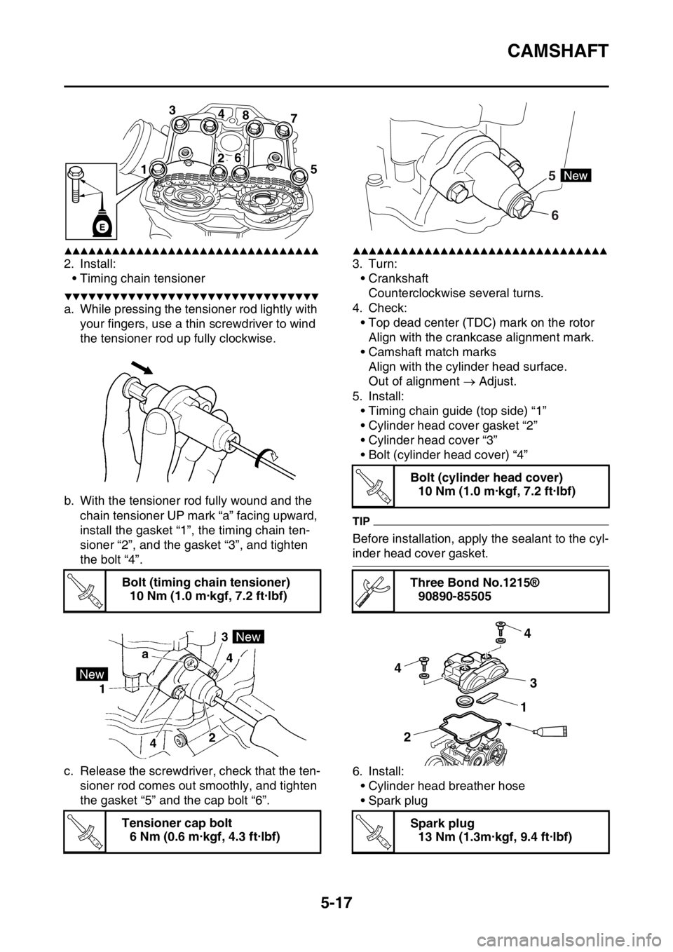
2. Install:
• Timing chain tensioner
▼▼▼▼▼▼▼▼▼▼▼▼▼▼▼▼▼▼▼▼▼▼▼▼▼▼▼▼▼▼▼▼
a. While pressing the tensioner rod lightly with
your fingers, use a thin screwdriver to wind
the tensioner rod up fully clockwise.
b. With the tensioner rod fully wound and the
chain tensioner UP mark “a” facing upward,
install the gasket “1”, the timing chain ten-
sioner “2”, and the gasket “3”, and tighten
the bolt “4”.
c. Release the screwdriver, check that the ten-
sioner rod comes out smoothly, and tighten
the gasket “5” and the cap bolt “6”.
▲▲▲▲▲▲▲▲▲▲▲▲▲▲▲▲▲▲▲▲▲▲▲▲▲▲▲▲▲▲▲▲
3. Turn:
• Crankshaft
Counterclockwise several turns.
4. Check:
• Top dead center (TDC) mark on the rotor
Align with the crankcase alignment mark.
• Camshaft match marks
Align with the cylinder head surface.
Out of alignment Adjust.
5. Install:
• Timing chain guide (top side) “1”
• Cylinder head cover gasket “2”
• Cylinder head cover “3”
• Bolt (cylinder head cover) “4”
TIP
Before installation, apply the sealant to the cyl-
inder head cover gasket.
6. Install:
• Cylinder head breather hose
• Spark plug Bolt (timing chain tensioner)
10 Nm (1.0 m·kgf, 7.2 ft·lbf)
Tensioner cap bolt
6 Nm (0.6 m·kgf, 4.3 ft·lbf)
3
4
8
7
15
26
E
T R..
T R..
Bolt (cylinder head cover)
10 Nm (1.0 m·kgf, 7.2 ft·lbf)
Three Bond No.1215®
90890-85505
Spark plug
13 Nm (1.3m·kgf, 9.4 ft·lbf)
6 5
T R..
4
4
3
21
T R..
Page 231 of 356

CLUTCH
5-38
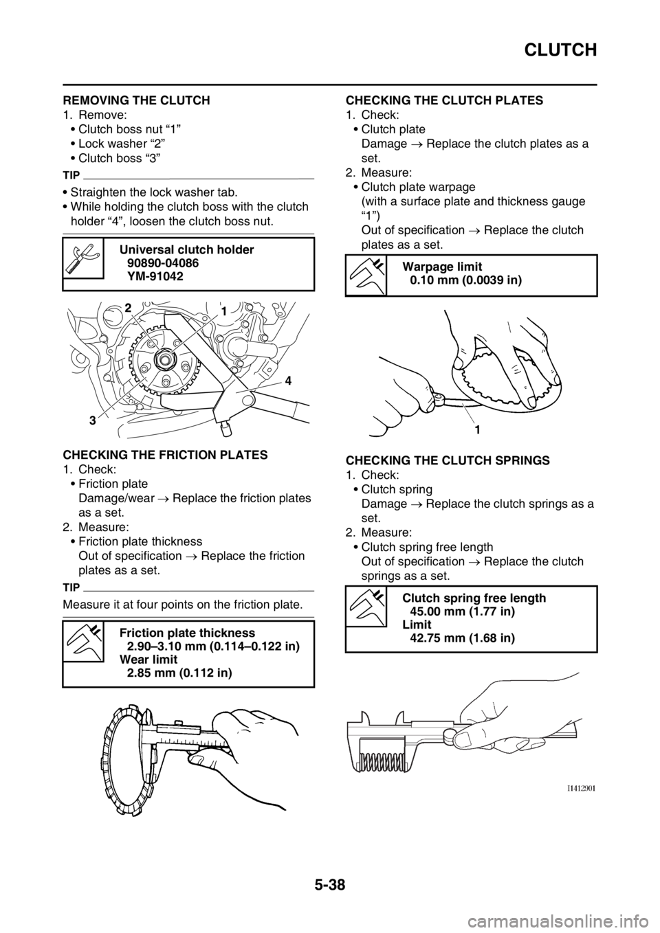
EAS1SM9231REMOVING THE CLUTCH
1. Remove:
• Clutch boss nut “1”
• Lock washer “2”
• Clutch boss “3”
TIP
• Straighten the lock washer tab.
• While holding the clutch boss with the clutch
holder “4”, loosen the clutch boss nut.
EAS1SM9232CHECKING THE FRICTION PLATES
1. Check:
• Friction plate
Damage/wear Replace the friction plates
as a set.
2. Measure:
• Friction plate thickness
Out of specification Replace the friction
plates as a set.
TIP
Measure it at four points on the friction plate.
EAS1SM9233CHECKING THE CLUTCH PLATES
1. Check:
• Clutch plate
Damage Replace the clutch plates as a
set.
2. Measure:
• Clutch plate warpage
(with a surface plate and thickness gauge
“1”)
Out of specification Replace the clutch
plates as a set.
EAS1SM9234CHECKING THE CLUTCH SPRINGS
1. Check:
• Clutch spring
Damage Replace the clutch springs as a
set.
2. Measure:
• Clutch spring free length
Out of specification Replace the clutch
springs as a set. Universal clutch holder
90890-04086
YM-91042
Friction plate thickness
2.90–3.10 mm (0.114–0.122 in)
Wear limit
2.85 mm (0.112 in)
34
12
Warpage limit
0.10 mm (0.0039 in)
Clutch spring free length
45.00 mm (1.77 in)
Limit
42.75 mm (1.68 in)
Page 234 of 356

CLUTCH
5-41
EAS1SM9244INSTALLING THE CLUTCH
1. Install:
• Push lever shaft “1”
TIP
• Apply the lithium soap base grease on the oil
seal lip.
• Before installation, apply the engine oil to the
push lever shaft sliding surface.
2. Install:
• Primary driven gear “1”
• Thrust washer “2”
• Clutch boss “3”
TIP
Apply the engine oil on the primary driven gear
inner circumference.
3. Install:
• Lock washer “1”
• Clutch boss nut “2”
ECA1DX1020
NOTICE
Make sure to tighten to specification; other-
wise, it may damage the other part that is
fastened together.
TIP
Use the clutch holding tool “3” to hold the clutch
boss.4. Bend the lock washer “1” tab.
5. Install:
• Friction plates “1”
• Clutch plate “2”
TIP
• Install the clutch plates and friction plates al-
ternately on the clutch boss, starting with a
friction plate and ending with a friction plate.
• Apply the engine oil on the friction plates and
clutch plates.
Clutch boss nut
75 Nm (7.5 m·kgf, 54 ft·lbf)
1
New
T R..
Clutch holder
90890-04086
YM-91042
3
21
1
1
1
2 2
2
1
Page 239 of 356
KICKSTATER
5-46
3. Install:
•Transmission
TIP
Slide the spring guide into the kick shaft, make
sure the groove “a” in the spring guide fits on
the stopper of the torsion spring.
4. Install:
• Kick shaft assembly “1”
TIP
• Before installation, apply molybdenum disul-
fide grease to the contacting surfaces of the
kick shaft ratchet wheel guide “2” and the kick
shaft stopper “a”.
• Apply the engine oil on the kick shaft.
• Slide the kick shaft assembly into the crank-
case and make sure the kick shaft stopper “a”
fits into the kick shaft ratchet wheel guide.5. Install:
• Torsion spring “1”
TIP
Turn the torsion spring clockwise and hook into
the proper hole “a” in the crankcase.
EAS1SM9251INSTALLING THE KICK IDLE GEAR
1. Install:
• Kick idle gear “1”
• Washer “2”
• Circlip “3”
TIP
• Apply the engine oil on the kick idle gear inner
circumference.
• Install the kick idle gear with its depressed
side “a” toward you.
1 2a b
New
Page 242 of 356
SHIFT SHAFT
5-49
EAS1SM9253REMOVING THE SHIFT GUIDE AND SHIFT
LEVER ASSEMBLY
1. Remove:
• Bolt (shift guide)
• Shift guide “1”
• Shift lever assembly “2”
TIP
Make sure that the shift lever assembly is re-
moved together with the shift guide.
EAS1SM9254REMOVING THE SEGMENT
1. Remove:
• Bolt (segment) “1”
• Segment “2”
TIP
Turn the segment counterclockwise until it
stops and loosen the bolt.
ECA
NOTICE
If the segment gets an impact, the stopper
lever may be damaged. Take care not to
give an impact to it when removing the bolt.
EAS1SM9255CHECKING THE SHIFT SHAFT
1. Check:
• Shift shaft “1”
Bends/damage/wear Replace.
• Shift shaft spring “2”
Damage/wear Replace.
EAS1SM9256CHECKING THE SHIFT GUIDE AND SHIFT
LEVER ASSEMBLY
1. Check:
• Shift guide “1”
• Shift lever “2”
•Pawl “3”
• Pawl pin “4”
• Spring “5”
Wear/damage Replace.
EAS1SM9257CHECKING THE STOPPER LEVER
1. Check:
• Stopper lever “1”
Wear/damage Replace.
• Torsion spring “2”
Broken Replace.
1
2
1
2
3
4
5
12