Page 185 of 356

SWINGARM
4-61
EAS1SM9183REMOVING THE SWINGARM
1. Use a suitable stand to raise the rear wheel
off the ground.
EWA
WARNING
Securely support the vehicle so that there is
no danger of it falling over.
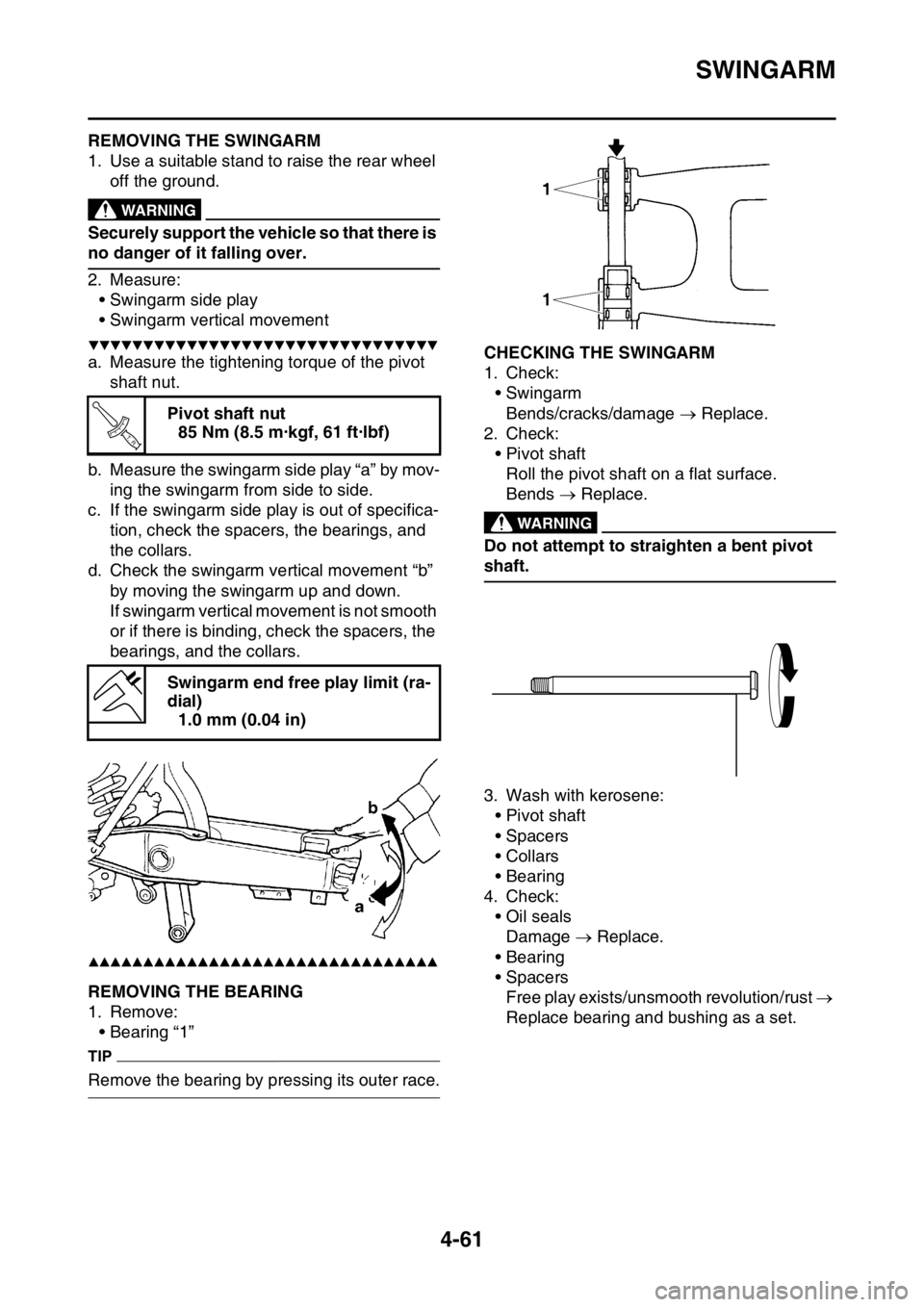
2. Measure:
• Swingarm side play
• Swingarm vertical movement
▼▼▼▼▼▼▼▼▼▼▼▼▼▼▼▼▼▼▼▼▼▼▼▼▼▼▼▼▼▼▼▼
a. Measure the tightening torque of the pivot
shaft nut.
b. Measure the swingarm side play “a” by mov-
ing the swingarm from side to side.
c. If the swingarm side play is out of specifica-
tion, check the spacers, the bearings, and
the collars.
d. Check the swingarm vertical movement “b”
by moving the swingarm up and down.
If swingarm vertical movement is not smooth
or if there is binding, check the spacers, the
bearings, and the collars.
▲▲▲▲▲▲▲▲▲▲▲▲▲▲▲▲▲▲▲▲▲▲▲▲▲▲▲▲▲▲▲▲
EAS1SM9184REMOVING THE BEARING
1. Remove:
• Bearing “1”
TIP
Remove the bearing by pressing its outer race.
EAS1SM9185CHECKING THE SWINGARM
1. Check:
• Swingarm
Bends/cracks/damage Replace.
2. Check:
• Pivot shaft
Roll the pivot shaft on a flat surface.
Bends Replace.
EWA
WARNING
Do not attempt to straighten a bent pivot
shaft.
3. Wash with kerosene:
• Pivot shaft
• Spacers
•Collars
• Bearing
4. Check:
• Oil seals
Damage Replace.
• Bearing
• Spacers
Free play exists/unsmooth revolution/rust
Replace bearing and bushing as a set. Pivot shaft nut
85 Nm (8.5 m·kgf, 61 ft·lbf)
Swingarm end free play limit (ra-
dial)
1.0 mm (0.04 in)
T R..
Page 209 of 356

CAMSHAFT
5-16
EAS1SM9210CHECKING THE DECOMPRESSION SYS-
TEM
1. Check:
• Decompression system
▼▼▼▼▼▼▼▼▼▼▼▼▼▼▼▼▼▼▼▼▼▼▼▼▼▼▼▼▼▼▼▼
a. Check that the decompressor cam “1”
moves smoothly.
b. Check that the decompressor lever pin “2”
projects from the camshaft.
▲▲▲▲▲▲▲▲▲▲▲▲▲▲▲▲▲▲▲▲▲▲▲▲▲▲▲▲▲▲▲▲
EAS1SM9211INSTALLING THE CAMSHAFTS
1. Install:
• Exhaust camshaft “1”
• Intake camshaft “2”
▼▼▼▼▼▼▼▼▼▼▼▼▼▼▼▼▼▼▼▼▼▼▼▼▼▼▼▼▼▼▼▼
a. Turn the crankshaft counterclockwise with a
wrench.
TIP
• Apply molybdenum disulfide oil to the cam-
shafts.
• Apply the engine oil on the decompression
system.
b. Align the top dead center (TDC) mark “a” on
the rotor with the alignment mark “b” on the
crankcase cover.c. Fit the timing chain “3” onto both camshaft
sprockets and install the camshafts on the
cylinder head.
TIP
Make sure that the alignment mark “c” on the
exhaust camshaft sprocket and the alignment
mark “d” on the intake camshaft sprocket are
aligned with the edge of the cylinder head.
ECA33DD029NOTICE
Do not turn the crankshaft during the cam-
shaft installation. Damage or improper
valve timing will result.
d. Install the clips, the camshaft caps and the
bolts (camshaft cap).
TIP
• Before installing the clips, cover the cylinder
head with a clean cloth to prevent the clips
from coming off into the cylinder head cavity.
• Apply the engine oil to the threads and con-
tact surfaces.
• Tighten the bolts to the specified torque in two
or three steps in the proper tightening se-
quence as shown.
ECA33DD030NOTICE
The bolts (camshaft cap) must be tightened
evenly, or damage to the cylinder head,
camshaft caps, and camshaft will result.
1
2
Bolt (camshaft cap)
10 Nm (1.0 m·kgf, 7.2 ft·lbf)
b
a
dc
3
T R..
Page 214 of 356
CYLINDER HEAD
5-21
EAS1SM9216INSTALLING THE CYLINDER HEAD
1. Install:
• Timing chain guide (intake side) “1”
• Dowel pins “2”
• Cylinder head gasket “3”
• Dowel pins “4”
TIP
• Install the cylinder head gasket with its char-
acter stamp “a” rearward of the vehicle as
shown.
• While pulling up the timing chain, install the
timing chain guide (intake side) and the cylin-
der head.
2. Install:
• Cylinder head “1”
• Cylinder head bolt “2”
• Cylinder head nut “3”
3. Tighten:
• Cylinder head bolt “1” – “4”
• Cylinder head nut “5”, “6”
TIP
• Apply molybdenum disulfide grease to the
threads and contact surfaces of the bolts and
to both contact surfaces of the washers.
• Tighten the bolts and nuts to the specified
torque in two or three steps in the proper tight-
ening sequence as shown.
Cylinder head bolt “1” – “4”
33 Nm (3.3 m·kgf, 24 ft·lbf)
Cylinder head nut “5”, “6”
10 Nm (1.0 m·kgf, 7.2 ft·lbf)
New
12
24
3
a
1
3 22
T R..
15
6
42
3 FWD
x2 x4
Page 349 of 356

CHASSIS
10-6
EAS1SM9378SUSPENSION SETTING (FRONT FORK)
TIP
• If any of the following symptoms is experienced with the standard position as the base, make reset-
ting by reference to the adjustment procedure given in the same chart.
• Before any change, set the rear shock absorber sunken length to the standard figure 90–100 mm
(3.5–3.9 in).
SymptomSection
Check Adjust
JumpLarge
gapMedi-
um
gapSmall
gap
Stiff over entire
rangeCompression
damping forceTurn adjuster counterclock-
wise (about 2 clicks) to de-
crease damping.
Oil amount Decrease oil amount by about
5–10 cm
3 (0.2–0.3 US oz, 0.2–
0.4 Imp.oz).
Spring Replace with soft spring.
Unsmooth
movement over
entire rangeOuter tube
Inner tubeCheck for any bends, dents,
other noticeable scars, etc. If
any, replace affected parts.
Slide metal Replace with a new one for ex-
tended use.
Piston metal Replace with a new one for ex-
tended use.
Lower bracket
tightening
torqueRetighten to specified torque.
Poor initial
movementRebound
damping forceTurn adjuster counterclock-
wise (about 2 clicks) to de-
crease damping.
Oil seals Apply grease in oil seal wall.
Soft over entire
range, bottom-
ing outCompression
damping forceTurn adjuster clockwise (about
2 clicks) to increase damping.
Oil amount Increase oil amount by about
5–10 cm
3 (0.2–0.3 US oz, 0.2–
0.4 Imp.oz).
Spring Replace with stiff spring.
Stiff toward
stroke endOil amountDecrease oil amount by about
5 cm
3 (0.2 US oz, 0.2 Imp.oz).
Soft toward
stroke end, bot-
toming outOil amountIncrease oil amount by about 5
cm
3 (0.2 US oz, 0.2 Imp.oz).
Stiff initial
movementCompression
damping forceTurn adjuster counterclock-
wise (about 2 clicks) to de-
crease damping.