2016 YAMAHA YZ250F length
[x] Cancel search: lengthPage 106 of 356

CHASSIS
3-22
EAS1SM9087
CHASSIS
EAS1SM9088BLEEDING THE BRAKE SYSTEMEWA13100
WARNING
Bleed the brake system whenever:
• The system is disassembled.
• A brake hose is loosened, disconnected,
or replaced.
• The brake fluid level is very low.
• Brake operation is faulty.
1. Remove:
• Brake master cylinder cap
• Reservoir diaphragm
• Reservoir float (front brake)
• Protector (rear brake)
TIP
• Be careful not to spill any brake fluid or allow
the reservoir to overflow.
• Make sure that there is enough brake fluid be-
fore applying the brake. Ignoring this precau-
tion could allow air to enter the brake system,
considerably lengthening the bleeding proce-
dure.
• If bleeding is difficult, it may be necessary to
let the brake fluid settle for a few hours. Re-
peat the bleeding procedure when the tiny
bubbles in the hose have disappeared.
2. Bleed the brake system.
▼▼▼▼▼▼▼▼▼▼▼▼▼▼▼▼▼▼▼▼▼▼▼▼▼▼▼▼▼▼▼▼
a. Fill the reservoir to the proper level with the
recommended brake fluid.
b. Install the reservoir diaphragm.
c. Connect the plastic hose “1” to the bleed
screw “2” securely, and place a container
under the end of the plastic hose.d. Slowly apply the brake several times.
e. Fully pull the brake lever or fully press down
the brake pedal and hold it in position.
f. Loosen the bleed screw.
TIP
Loosening the bleed screw will release the
pressure in the brake caliper and cause the
brake lever to contact the throttle grip or the
brake pedal to fully extend.
g. Tighten the bleed screw and then release
the brake lever or brake pedal.
h. Repeat steps (d) to (g) until all of the air bub-
bles have disappeared from the brake fluid
in the plastic hose.
TIP
During the procedure, keep adding brake fluid
to the reservoir.
ECA
NOTICE
Brake fluid may erode painted surfaces or
plastic parts. Always clean up spilled fluid
immediately.
i. Tighten the bleed screw.
j. Pour brake fluid to the reservoir up to the
specified level.
Refer to “CHECKING THE BRAKE FLUID
LEVEL” on page 3-27.
EWA13110
WARNING
After bleeding the hydraulic brake system,
check the brake operation.
▲▲▲▲▲▲▲▲▲▲▲▲▲▲▲▲▲▲▲▲▲▲▲▲▲▲▲▲▲▲▲▲
1 2
A
A. Front
B. Rear
Bleed screw
6 Nm (0.6 m·kgf, 4.3 ft·lbf)
2
1B
T R..
Page 115 of 356

CHASSIS
3-31
EAS1SM9102CHECKING THE SWINGARM OPERATION
1. Check:
• Swingarm smooth action
• Swingarm free play
Refer to “SWINGARM” on page 4-60.
EAS1SM9103CHECKING THE REAR SUSPENSION
1. Stand the vehicle upright on a level surface.
EWA
WARNING
Securely support the vehicle so that there is
no danger of it falling over.
2. Check:
• Rear shock absorber assembly
Gas leaks/oil leaks Replace the rear
shock absorber assembly.
Refer to “REAR SHOCK ABSORBER AS-
SEMBLY” on page 4-53.
3. Check:
• Rear shock absorber assembly smooth ac-
tion
• Rear suspension link smooth action
Sit astride the seat and shake your body up
and down several times to check whether
the rear shock absorber assembly operates
smoothly.
Unsmooth operation Correct or replace.
Refer to “REAR SHOCK ABSORBER AS-
SEMBLY” on page 4-53.
EAS1SM9104ADJUSTING THE REAR SHOCK ABSORB-
ER ASSEMBLY
Use a suitable stand to raise the rear wheel off
the ground.
EWA13120
WARNING
Securely support the vehicle so that there is
no danger of it falling over.
Spring preload
ECA@
NOTICE
Do not turn the adjuster forcibly beyond its
adjusting range.1. Remove:
• Rear frame
Refer to “REAR SHOCK ABSORBER AS-
SEMBLY” on page 4-53.
2. Adjust:
• Spring preload
▼▼▼▼▼▼▼▼▼▼▼▼▼▼▼▼▼▼▼▼▼▼▼▼▼▼▼▼▼▼▼▼
a. Loosen the locknut “1”.
b. Loosen the adjuster “2” until there is some
clearance between the spring and the ad-
juster.
c. Measure the spring free length “a”.
d. Turn the adjuster in the direction of “b” or “c”
to make an adjustment.
TIP
• Be sure to remove all dirt and mud from
around the locknut and adjusting ring before
adjustment.
• The length of the spring (installed) changes
1.5 mm (0.06 in) per turn of the adjusting ring.
Direction “b”
Spring preload is increased (suspen-
sion is harder).
Direction “c”
Spring preload is decreased (suspen-
sion is softer).
Spring preload adjusting positions
Minimum
Position in which the spring is
turned in 1.5 mm (0.06 in) from
its free length.
Standard
Position in which the spring is
turned in 10 mm (0.39 in) from its
free length.
Maximum
Position in which the spring is
turned in 18 mm (0.71 in) from its
free length.
Page 164 of 356

FRONT FORK
4-40
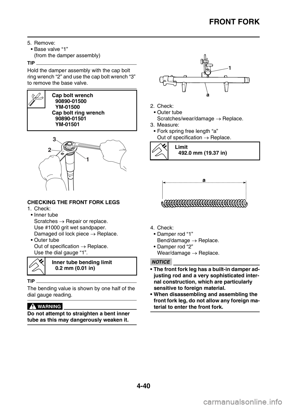
5. Remove:
• Base valve “1”
(from the damper assembly)
TIP
Hold the damper assembly with the cap bolt
ring wrench “2” and use the cap bolt wrench “3”
to remove the base valve.
EAS1SM9166CHECKING THE FRONT FORK LEGS
1. Check:
• Inner tube
Scratches Repair or replace.
Use #1000 grit wet sandpaper.
Damaged oil lock piece Replace.
• Outer tube
Out of specification Replace.
Use the dial gauge “1”.
TIP
The bending value is shown by one half of the
dial gauge reading.
EWA13650
WARNING
Do not attempt to straighten a bent inner
tube as this may dangerously weaken it.2. Check:
• Outer tube
Scratches/wear/damage Replace.
3. Measure:
• Fork spring free length “a”
Out of specification Replace.
4. Check:
• Damper rod “1”
Bend/damage Replace.
• Damper rod “2”
Wear/damage Replace.
ECA1DX1010
NOTICE
• The front fork leg has a built-in damper ad-
justing rod and a very sophisticated inter-
nal construction, which are particularly
sensitive to foreign material.
• When disassembling and assembling the
front fork leg, do not allow any foreign ma-
terial to enter the front fork. Cap bolt wrench
90890-01500
YM-01500
Cap bolt ring wrench
90890-01501
YM-01501
Inner tube bending limit
0.2 mm (0.01 in)
1 23
Limit
492.0 mm (19.37 in)
Page 188 of 356

CHAIN DRIVE
4-64
EAS1SM9188REMOVING THE DRIVE CHAIN
1. Use a suitable stand to raise the rear wheel
off the ground.
EWA13120
WARNING
Securely support the vehicle so that there is
no danger of it falling over.
2. Remove:
• Joint clip
• Drive chain joint “1”
• Drive chain “2”
EAS1SM9189CHECKING THE DRIVE CHAIN
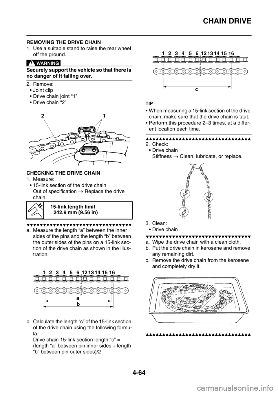
1. Measure:
• 15-link section of the drive chain
Out of specification Replace the drive
chain.
▼▼▼▼▼▼▼▼▼▼▼▼▼▼▼▼▼▼▼▼▼▼▼▼▼▼▼▼▼▼▼▼
a. Measure the length “a” between the inner
sides of the pins and the length “b” between
the outer sides of the pins on a 15-link sec-
tion of the drive chain as shown in the illus-
tration.
b. Calculate the length “c” of the 15-link section
of the drive chain using the following formu-
la.
Drive chain 15-link section length “c” =
(length “a” between pin inner sides + length
“b” between pin outer sides)/2
TIP
• When measuring a 15-link section of the drive
chain, make sure that the drive chain is taut.
• Perform this procedure 2–3 times, at a differ-
ent location each time.
▲▲▲▲▲▲▲▲▲▲▲▲▲▲▲▲▲▲▲▲▲▲▲▲▲▲▲▲▲▲▲▲
2. Check:
•Drive chain
Stiffness Clean, lubricate, or replace.
3. Clean:
•Drive chain
▼▼▼▼▼▼▼▼▼▼▼▼▼▼▼▼▼▼▼▼▼▼▼▼▼▼▼▼▼▼▼▼
a. Wipe the drive chain with a clean cloth.
b. Put the drive chain in kerosene and remove
any remaining dirt.
c. Remove the drive chain from the kerosene
and completely dry it.
▲▲▲▲▲▲▲▲▲▲▲▲▲▲▲▲▲▲▲▲▲▲▲▲▲▲▲▲▲▲▲▲
15-link length limit
242.9 mm (9.56 in)
Page 220 of 356

VALVES AND VALVE SPRINGS
5-27
h. Install the valve into the cylinder head.
i. Press the valve through the valve guide and
onto the valve seat to make a clear impres-
sion.
j. Measure the valve seat contact width “c”
again. If the valve seat contact width is out of
specification, reface and lap the valve seat.
▲▲▲▲▲▲▲▲▲▲▲▲▲▲▲▲▲▲▲▲▲▲▲▲▲▲▲▲▲▲▲▲
EAS1SM9221CHECKING THE VALVE SPRINGS
1. Measure:
• Valve spring free length “a”
Out of specification Replace the valve
spring.2. Measure:
• Compressed valve spring force “a”
Out of specification Replace the valve
spring.
3. Measure:
• Valve spring tilt “a”
Out of specification Replace the valve
spring.
Free length (intake)
36.69 mm (1.44 in)
Limit
34.85 mm (1.37 in)
Free length (exhaust)
34.86 mm (1.37 in)
Limit
33.11 mm (1.30 in)
b. Installed length
Installed compression spring
force (intake)
146.00–168.00 N (14.89–17.13
kgf, 32.82–37.77 lbf)
Installed compression spring
force (exhaust)
137.00–157.00 N (13.97–16.01
kgf, 30.80–35.29 lbf)
Installed length (intake)
31.40 mm (1.24 in)
Installed length (exhaust)
28.50 mm (1.12 in)
Spring tilt (intake)
2.5 °/1.6 mm (2.5 °/0.06 in)
Spring tilt (exhaust)
2.5 °/1.5 mm (2.5 °/0.06 in)
Page 231 of 356

CLUTCH
5-38
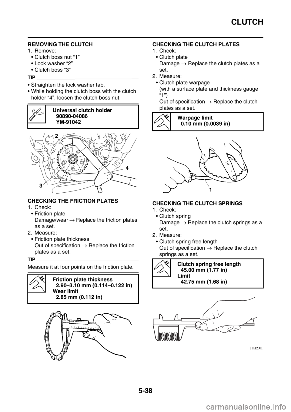
EAS1SM9231REMOVING THE CLUTCH
1. Remove:
• Clutch boss nut “1”
• Lock washer “2”
• Clutch boss “3”
TIP
• Straighten the lock washer tab.
• While holding the clutch boss with the clutch
holder “4”, loosen the clutch boss nut.
EAS1SM9232CHECKING THE FRICTION PLATES
1. Check:
• Friction plate
Damage/wear Replace the friction plates
as a set.
2. Measure:
• Friction plate thickness
Out of specification Replace the friction
plates as a set.
TIP
Measure it at four points on the friction plate.
EAS1SM9233CHECKING THE CLUTCH PLATES
1. Check:
• Clutch plate
Damage Replace the clutch plates as a
set.
2. Measure:
• Clutch plate warpage
(with a surface plate and thickness gauge
“1”)
Out of specification Replace the clutch
plates as a set.
EAS1SM9234CHECKING THE CLUTCH SPRINGS
1. Check:
• Clutch spring
Damage Replace the clutch springs as a
set.
2. Measure:
• Clutch spring free length
Out of specification Replace the clutch
springs as a set. Universal clutch holder
90890-04086
YM-91042
Friction plate thickness
2.90–3.10 mm (0.114–0.122 in)
Wear limit
2.85 mm (0.112 in)
34
12
Warpage limit
0.10 mm (0.0039 in)
Clutch spring free length
45.00 mm (1.77 in)
Limit
42.75 mm (1.68 in)
Page 343 of 356

10
TUNING
CHASSIS........................................................................................................ 10-1
SELECTION OF THE SECONDARY REDUCTION
RATIO (SPROCKET) .............................................................................. 10-1
DRIVE AND REAR WHEEL SPROCKETS SETTING PARTS ................ 10-1
TIRE PRESSURE..................................................................................... 10-2
FRONT FORK SETTING.......................................................................... 10-2
CHANGE IN AMOUNT AND CHARACTERISTICS OF FORK OIL.......... 10-2
SETTING OF SPRING AFTER REPLACEMENT .................................... 10-3
FRONT FORK SETTING PARTS............................................................. 10-3
REAR SUSPENSION SETTING .............................................................. 10-3
CHOOSING SET LENGTH ...................................................................... 10-3
SETTING OF SPRING AFTER REPLACEMENT .................................... 10-4
REAR SHOCK ABSORBER SETTING PARTS ....................................... 10-5
SUSPENSION SETTING (FRONT FORK)............................................... 10-6
SUSPENSION SETTING (REAR SHOCK ABSORBER) ......................... 10-7
Page 346 of 356

CHASSIS
10-3
EAS1SM9372SETTING OF SPRING AFTER REPLACE-
MENT
As the front fork setting can be easily affected
by the rear suspension, take care so that the
front and the rear are balanced (in position etc.)
when setting the front fork.
1. Use of soft spring
• Change the rebound damping force.
Turn out one or two clicks.
• Change the compression damping force.
Turn in one or two clicks.
TIP
Generally a soft spring gives a soft riding feel-
ing. Rebound damping tends to become stron-
ger and the front fork may sink deeply over a
series of gaps.
2. Use of stiff spring
• Change the rebound damping force.
Turn in one or two clicks.
• Change the compression damping force.
Turn out one or two clicks.
TIP
Generally a stiff spring gives a stiff riding feel-
ing. Rebound damping tends to become weak-
er, resulting in lack of a sense of contact with
the road surface or in a vibrating handlebar.
EAS1SM9373FRONT FORK SETTING PARTS
• Front fork spring “1”
*Except for USA and CAN
TIP
The I.D. mark (slits) “a” is proved on the end of
the spring.
EAS1SM9374REAR SUSPENSION SETTING
The rear shock absorber setting should be
made depending on the rider’s feeling of an ac-
tual run and the circuit conditions.
The rear suspension setting includes the fol-
lowing two factors:
1. Setting of spring preload
• Change the set length of the spring.
• Change the spring.
2. Setting of damping force
• Change the rebound damping force.
• Change the compression damping force.
EAS1SM9375CHOOSING SET LENGTH
1. Place a stand or a block under the engine to
put the rear wheel above the floor, and mea-
sure the length “a” between the rear wheel
axle center and the rear fender holding bolt. TypeSpring
rate N/
mmPart numberI.D.
Mark
(slits)
SOFT 4.5 1SL-23141-20 |-||
STD*4.61SM-23141-00 —
1SL-23141-30 |-|||
STD 4.71SL-23141-10 —
1SL-23141-40 |-||||
4.8 1SL-23141-50 |-|||||
4.91SL-23141-60 ||-||
STIFF 5.0 1SL-23141-70 ||-|||
a
1