2016 YAMAHA YZ250F checking oil
[x] Cancel search: checking oilPage 141 of 356
FRONT BRAKE
4-17
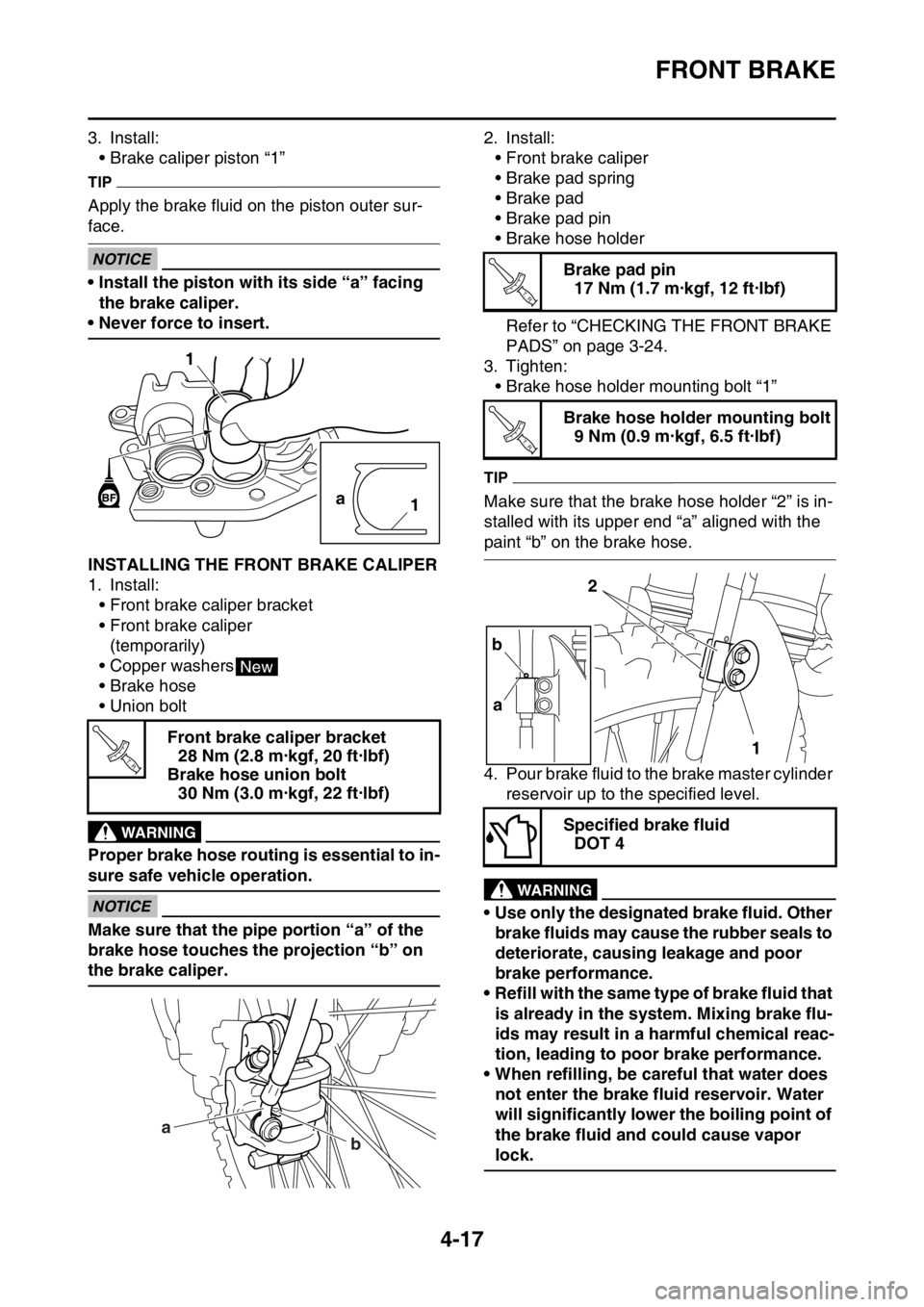
3. Install:
• Brake caliper piston “1”
TIP
Apply the brake fluid on the piston outer sur-
face.
ECANOTICE
• Install the piston with its side “a” facing
the brake caliper.
• Never force to insert.
EAS1SM9141INSTALLING THE FRONT BRAKE CALIPER
1. Install:
• Front brake caliper bracket
• Front brake caliper
(temporarily)
• Copper washers
• Brake hose
• Union bolt
EWAWARNING
Proper brake hose routing is essential to in-
sure safe vehicle operation.
ECANOTICE
Make sure that the pipe portion “a” of the
brake hose touches the projection “b” on
the brake caliper.2. Install:
• Front brake caliper
• Brake pad spring
• Brake pad
• Brake pad pin
• Brake hose holder
Refer to “CHECKING THE FRONT BRAKE
PADS” on page 3-24.
3. Tighten:
• Brake hose holder mounting bolt “1”
TIP
Make sure that the brake hose holder “2” is in-
stalled with its upper end “a” aligned with the
paint “b” on the brake hose.
4. Pour brake fluid to the brake master cylinder
reservoir up to the specified level.
EWA
WARNING
• Use only the designated brake fluid. Other
brake fluids may cause the rubber seals to
deteriorate, causing leakage and poor
brake performance.
• Refill with the same type of brake fluid that
is already in the system. Mixing brake flu-
ids may result in a harmful chemical reac-
tion, leading to poor brake performance.
• When refilling, be careful that water does
not enter the brake fluid reservoir. Water
will significantly lower the boiling point of
the brake fluid and could cause vapor
lock.
ECA
Front brake caliper bracket
28 Nm (2.8 m·kgf, 20 ft·lbf)
Brake hose union bolt
30 Nm (3.0 m·kgf, 22 ft·lbf)
1
a
1
New
T R..
a
b
Brake pad pin
17 Nm (1.7 m·kgf, 12 ft·lbf)
Brake hose holder mounting bolt
9 Nm (0.9 m·kgf, 6.5 ft·lbf)
Specified brake fluid
DOT 4
T R..
T R..
2
1 b
a
Page 144 of 356
FRONT BRAKE
4-20
3. Pour brake fluid to the brake master cylinder
reservoir up to the specified level.
EWA13540
WARNING
• Use only the designated brake fluid. Other
brake fluids may cause the rubber seals to
deteriorate, causing leakage and poor
brake performance.
• Refill with the same type of brake fluid that
is already in the system. Mixing brake flu-
ids may result in a harmful chemical reac-
tion, leading to poor brake performance.
• When refilling, be careful that water does
not enter the brake master cylinder reser-
voir. Water will significantly lower the boil-
ing point of the brake fluid and could
cause vapor lock.
ECA13540
NOTICE
Brake fluid may damage painted surfaces
and plastic parts. Therefore, always clean
up any spilt brake fluid immediately.
4. Bleed:
• Brake system
Refer to “BLEEDING THE BRAKE SYS-
TEM” on page 3-22.
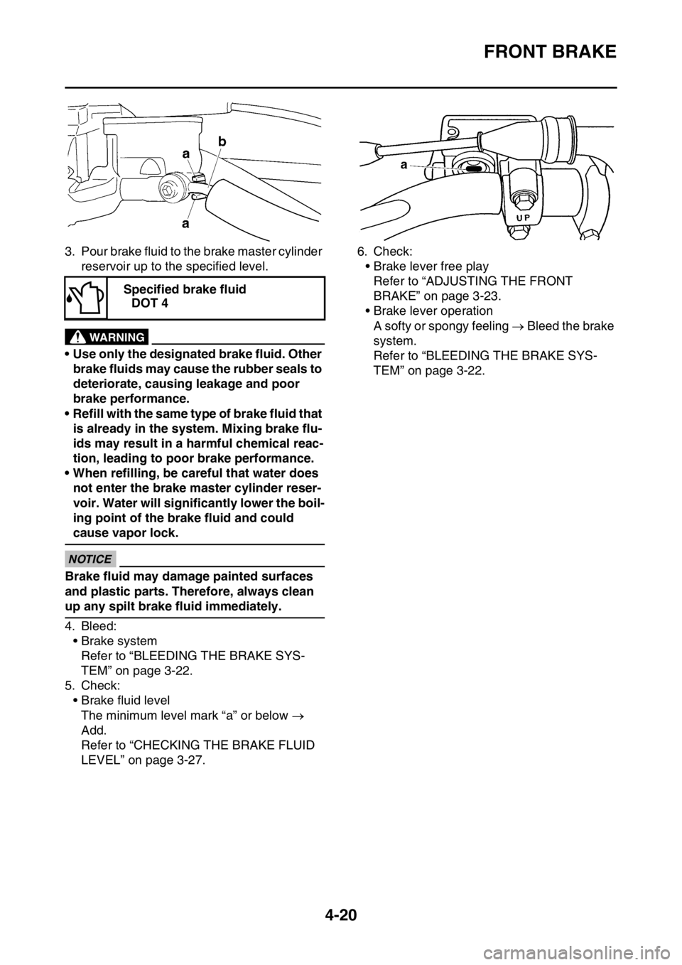
5. Check:
• Brake fluid level
The minimum level mark “a” or below
Add.
Refer to “CHECKING THE BRAKE FLUID
LEVEL” on page 3-27.6. Check:
• Brake lever free play
Refer to “ADJUSTING THE FRONT
BRAKE” on page 3-23.
• Brake lever operation
A softy or spongy feeling Bleed the brake
system.
Refer to “BLEEDING THE BRAKE SYS-
TEM” on page 3-22. Specified brake fluid
DOT 4
Page 152 of 356
REAR BRAKE
4-28
EWA
WARNING
• Use only the designated brake fluid. Other
brake fluids may cause the rubber seals to
deteriorate, causing leakage and poor
brake performance.
• Refill with the same type of brake fluid that
is already in the system. Mixing brake flu-
ids may result in a harmful chemical reac-
tion, leading to poor brake performance.
• When refilling, be careful that water does
not enter the brake fluid reservoir. Water
will significantly lower the boiling point of
the brake fluid and could cause vapor
lock.
ECA
NOTICE
Brake fluid may damage painted surfaces
and plastic parts. Therefore, always clean
up any spilt brake fluid immediately.
5. Bleed:
• Brake system
Refer to “BLEEDING THE BRAKE SYS-
TEM” on page 3-22.
6. Check:
• Brake fluid level
The minimum level mark “a” or below
Add.
Refer to “CHECKING THE BRAKE FLUID
LEVEL” on page 3-27.
7. Check:
• Brake pedal operation
A softy or spongy feeling Bleed the brake
system.
Refer to “BLEEDING THE BRAKE SYS-
TEM” on page 3-22.
EAS1SM9155REMOVING THE REAR BRAKE MASTER
CYLINDER
TIP
Before removing the rear brake master cylin-
der, drain the brake fluid from the entire brake
system.
1. Remove:
• Union bolt
• Copper washers
• Brake hose
TIP
To drain any remaining brake fluid, place a con-
tainer under the master cylinder and the end of
the brake hose.
EAS1SM9156CHECKING THE REAR BRAKE MASTER
CYLINDER
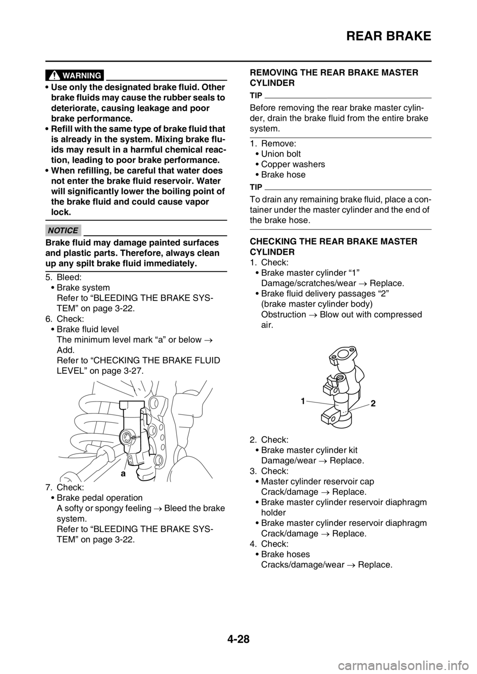
1. Check:
• Brake master cylinder “1”
Damage/scratches/wear Replace.
• Brake fluid delivery passages “2”
(brake master cylinder body)
Obstruction Blow out with compressed
air.
2. Check:
• Brake master cylinder kit
Damage/wear Replace.
3. Check:
• Master cylinder reservoir cap
Crack/damage Replace.
• Brake master cylinder reservoir diaphragm
holder
• Brake master cylinder reservoir diaphragm
Crack/damage Replace.
4. Check:
• Brake hoses
Cracks/damage/wear Replace.
a
1
2
Page 154 of 356
REAR BRAKE
4-30
2. Pour brake fluid to the brake fluid reservoir
up to the specified level.
EWA
WARNING
• Use only the designated brake fluid. Other
brake fluids may cause the rubber seals to
deteriorate, causing leakage and poor
brake performance.
• Refill with the same type of brake fluid that
is already in the system. Mixing brake flu-
ids may result in a harmful chemical reac-
tion, leading to poor brake performance.
• When refilling, be careful that water does
not enter the brake fluid reservoir. Water
will significantly lower the boiling point of
the brake fluid and could cause vapor
lock.
ECA
NOTICE
Brake fluid may damage painted surfaces
and plastic parts. Therefore, always clean
up any spilt brake fluid immediately.
3. Bleed:
• Brake system
Refer to “BLEEDING THE BRAKE SYS-
TEM” on page 3-22.
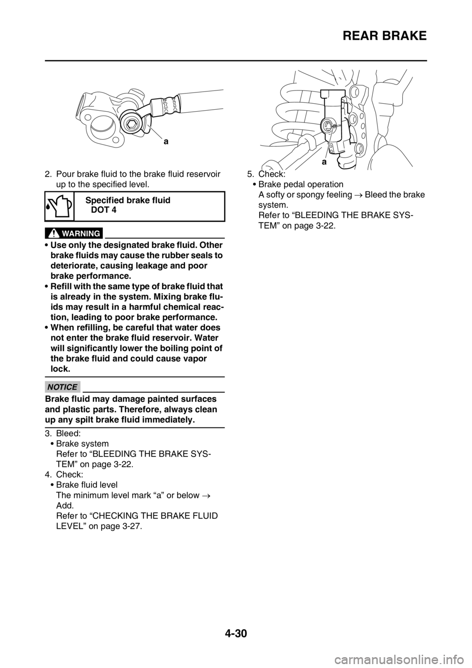
4. Check:
• Brake fluid level
The minimum level mark “a” or below
Add.
Refer to “CHECKING THE BRAKE FLUID
LEVEL” on page 3-27.5. Check:
• Brake pedal operation
A softy or spongy feeling Bleed the brake
system.
Refer to “BLEEDING THE BRAKE SYS-
TEM” on page 3-22. Specified brake fluid
DOT 4
a
a
Page 164 of 356
FRONT FORK
4-40
5. Remove:
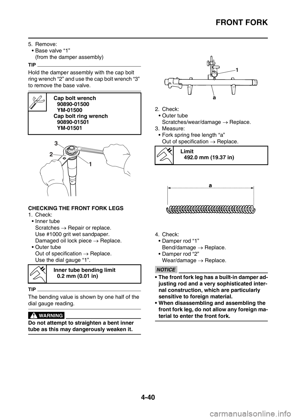
• Base valve “1”
(from the damper assembly)
TIP
Hold the damper assembly with the cap bolt
ring wrench “2” and use the cap bolt wrench “3”
to remove the base valve.
EAS1SM9166CHECKING THE FRONT FORK LEGS
1. Check:
• Inner tube
Scratches Repair or replace.
Use #1000 grit wet sandpaper.
Damaged oil lock piece Replace.
• Outer tube
Out of specification Replace.
Use the dial gauge “1”.
TIP
The bending value is shown by one half of the
dial gauge reading.
EWA13650
WARNING
Do not attempt to straighten a bent inner
tube as this may dangerously weaken it.2. Check:
• Outer tube
Scratches/wear/damage Replace.
3. Measure:
• Fork spring free length “a”
Out of specification Replace.
4. Check:
• Damper rod “1”
Bend/damage Replace.
• Damper rod “2”
Wear/damage Replace.
ECA1DX1010
NOTICE
• The front fork leg has a built-in damper ad-
justing rod and a very sophisticated inter-
nal construction, which are particularly
sensitive to foreign material.
• When disassembling and assembling the
front fork leg, do not allow any foreign ma-
terial to enter the front fork. Cap bolt wrench
90890-01500
YM-01500
Cap bolt ring wrench
90890-01501
YM-01501
Inner tube bending limit
0.2 mm (0.01 in)
1 23
Limit
492.0 mm (19.37 in)
Page 181 of 356

REAR SHOCK ABSORBER ASSEMBLY
4-57
2. Remove:
• Upper bearing “1”
TIP
Remove the bearing by pressing its outer race.
3. Remove:
• Lower bearing “1”
TIP
Remove the bearing by pressing its outer race.
EAS1SM9178CHECKING THE REAR SHOCK ABSORBER
ASSEMBLY
1. Check:
• Rear shock absorber rod
Bends/damage Replace the rear shock
absorber assembly.
• Rear shock absorber
Gas leaks/oil leaks Replace the rear
shock absorber assembly.
•Spring
Damage/wear Replace.
• Spring guide
Damage/wear Replace.
• Bearing
Damage/wear Replace.
•Bolts
Bends/damage/wear Replace.
EAS1SM9179CHECKING THE CONNECTING ARM AND
RELAY ARM
1. Check:
• Connecting arm
• Relay arm
Damage/wear Replace.
2. Check:
• Bearing
• Spacers
Damage/pitting/scratches Replace the
bearings and spacers as a set.
3. Check:
• Oil seals
Damage/pitting Replace.
EAS1SM9180INSTALLING THE RELAY ARM
1. Lubricate:
• Oil seals
• Bearing
• Spacers
• Washers
•Collars
2. Install:
• Bearing “1”
• Washer “2”
• Oil seals “3”
(to relay arm “4”)
3. Install:
• Bearing “1”
• Oil seals “2”
(to connecting arm “3”)
1
Recommended lubricant
Molybdenum disulfide grease
Installed depth “a”
0 mm (0 in)
Installed depth “a”
0 mm (0 in)
New
3 3
43
2 2
22
a
1
11
New
Page 185 of 356
SWINGARM
4-61
EAS1SM9183REMOVING THE SWINGARM
1. Use a suitable stand to raise the rear wheel
off the ground.
EWA
WARNING
Securely support the vehicle so that there is
no danger of it falling over.
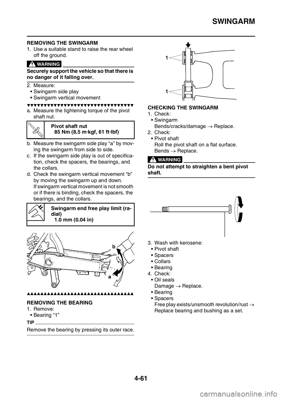
2. Measure:
• Swingarm side play
• Swingarm vertical movement
▼▼▼▼▼▼▼▼▼▼▼▼▼▼▼▼▼▼▼▼▼▼▼▼▼▼▼▼▼▼▼▼
a. Measure the tightening torque of the pivot
shaft nut.
b. Measure the swingarm side play “a” by mov-
ing the swingarm from side to side.
c. If the swingarm side play is out of specifica-
tion, check the spacers, the bearings, and
the collars.
d. Check the swingarm vertical movement “b”
by moving the swingarm up and down.
If swingarm vertical movement is not smooth
or if there is binding, check the spacers, the
bearings, and the collars.
▲▲▲▲▲▲▲▲▲▲▲▲▲▲▲▲▲▲▲▲▲▲▲▲▲▲▲▲▲▲▲▲
EAS1SM9184REMOVING THE BEARING
1. Remove:
• Bearing “1”
TIP
Remove the bearing by pressing its outer race.
EAS1SM9185CHECKING THE SWINGARM
1. Check:
• Swingarm
Bends/cracks/damage Replace.
2. Check:
• Pivot shaft
Roll the pivot shaft on a flat surface.
Bends Replace.
EWA
WARNING
Do not attempt to straighten a bent pivot
shaft.
3. Wash with kerosene:
• Pivot shaft
• Spacers
•Collars
• Bearing
4. Check:
• Oil seals
Damage Replace.
• Bearing
• Spacers
Free play exists/unsmooth revolution/rust
Replace bearing and bushing as a set. Pivot shaft nut
85 Nm (8.5 m·kgf, 61 ft·lbf)
Swingarm end free play limit (ra-
dial)
1.0 mm (0.04 in)
T R..
Page 192 of 356

CLUTCH......................................................................................................... 5-35
REMOVING THE CLUTCH ...................................................................... 5-38
CHECKING THE FRICTION PLATES...................................................... 5-38
CHECKING THE CLUTCH PLATES ........................................................ 5-38
CHECKING THE CLUTCH SPRINGS...................................................... 5-38
CHECKING THE CLUTCH HOUSING ..................................................... 5-39
CHECKING THE CLUTCH BOSS ............................................................ 5-39
CHECKING THE PRESSURE PLATE ..................................................... 5-39
CHECKING THE PUSH LEVER SHAFT .................................................. 5-39
CHECKING THE CLUTCH PUSH RODS ................................................ 5-39
CHECKING THE PRIMARY DRIVE GEAR .............................................. 5-39
CHECKING THE PRIMARY DRIVEN GEAR ........................................... 5-40
INSTALLING THE OIL SEAL................................................................... 5-40
INSTALLING THE RIGHT CRANKCASE COVER ................................... 5-40
INSTALLING THE CLUTCH ..................................................................... 5-41
INSTALLING THE KICKSTARTER LEVER ............................................. 5-43
KICKSTATER................................................................................................. 5-44
REMOVING THE KICK SHAFT ASSEMBLY ........................................... 5-45
CHECKING THE KICK SHAFT AND RATCHET WHEEL ........................ 5-45
CHECKING THE KICK GEAR, KICK IDLE GEAR AND
RATCHET WHEEL .................................................................................. 5-45
INSTALLING THE KICK SHAFT ASSEMBLY .......................................... 5-45
INSTALLING THE KICK IDLE GEAR ....................................................... 5-46
SHIFT SHAFT................................................................................................. 5-47
REMOVING THE SHIFT GUIDE AND SHIFT LEVER ASSEMBLY ......... 5-49
REMOVING THE SEGMENT ................................................................... 5-49
CHECKING THE SHIFT SHAFT .............................................................. 5-49
CHECKING THE SHIFT GUIDE AND SHIFT LEVER ASSEMBLY ......... 5-49
CHECKING THE STOPPER LEVER ....................................................... 5-49
INSTALLING THE STOPPER LEVER ..................................................... 5-50
INSTALLING THE SEGMENT.................................................................. 5-50
INSTALLING THE SHIFT GUIDE AND SHIFT LEVER ASSEMBLY ....... 5-50
INSTALLING THE SHIFT SHAFT ............................................................ 5-51
INSTALLING THE SHIFT PEDAL ............................................................ 5-51
OIL PUMP AND BALANCER GEAR............................................................. 5-52
REMOVING THE BALANCER ................................................................. 5-54
CHECKING THE PRIMARY DRIVE GEAR, BALANCER SHAFT DRIVE
GEAR, AND BALANCER WEIGHT GEAR .............................................. 5-54
CHECKING THE BALANCER .................................................................. 5-54
CHECKING THE OIL PUMP .................................................................... 5-54
ASSEMBLING THE OIL PUMP ................................................................ 5-55
INSTALLING THE OIL PUMP AND BALANCER GEAR .......................... 5-55