2016 YAMAHA XJR 1300 wheel
[x] Cancel search: wheelPage 67 of 98
Periodic maintenance an d a djustment
6-22
6
EAU22762
Drive chain slackThe drive chain slack should be
checked before each ride and adjusted
if necessary.
EAU51444
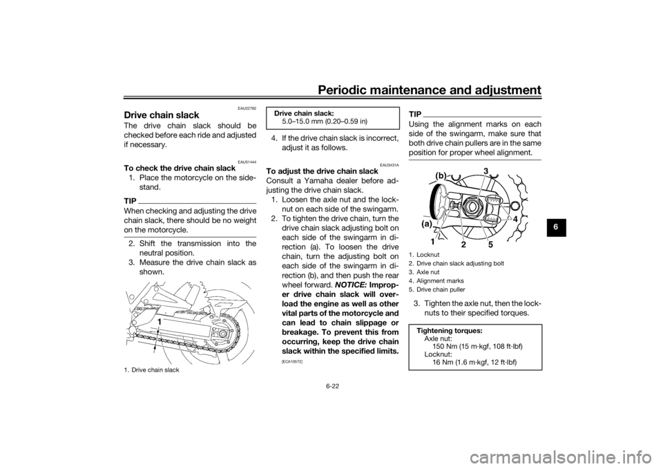
To check the d rive chain slack
1. Place the motorcycle on the side- stand.TIPWhen checking and adjusting the drive
chain slack, there should be no weight
on the motorcycle.2. Shift the transmission into the neutral position.
3. Measure the drive chain slack as shown. 4. If the drive chain slack is incorrect,
adjust it as follows.
EAU3431A
To a djust the drive chain slack
Consult a Yamaha dealer before ad-
justing the drive chain slack. 1. Loosen the axle nut and the lock- nut on each side of the swingarm.
2. To tighten the drive chain, turn the drive chain slack adjusting bolt on
each side of the swingarm in di-
rection (a). To loosen the drive
chain, turn the adjusting bolt on
each side of the swingarm in di-
rection (b), and then push the rear
wheel forward. NOTICE: Improp-
er drive chain slack will over-
loa d the en gine as well as other
vital parts of the motorcycle an d
can lea d to chain slippa ge or
b reakag e. To prevent this from
occurrin g, keep the d rive chain
slack within the specified limits.
[ECA10572]
TIPUsing the alignment marks on each
side of the swingarm, make sure that
both drive chain pullers are in the same
position for proper wheel alignment.3. Tighten the axle nut, then the lock-
nuts to their specified torques.
1. Drive chain slack
1
Drive chain slack:5.0–15.0 mm (0.20–0.59 in)
1. Locknut
2. Drive chain slack adjusting bolt
3. Axle nut
4. Alignment marks
5. Drive chain puller
Tightenin g torques:
Axle nut: 150 Nm (15 m·kgf, 108 ft·lbf)
Locknut:
16 Nm (1.6 m·kgf, 12 ft·lbf)
U2PNE1E0.book Page 22 Monday, December 28, 2015 11:03 AM
Page 72 of 98
Periodic maintenance an d a djustment
6-27
6
NOTICE
ECA10591
If any d amage is foun d or the front
fork does not operate smoothly,
have a Yamaha d ealer check or re-
pair it.
EAU23285
Checkin g the steerin gWorn or loose steering bearings may
cause danger. Therefore, the operation
of the steering must be checked as fol-
lows at the intervals specified in the
periodic maintenance and lubrication
chart.
1. Raise the front wheel off the ground. (See page 6-35.)
WARNING! To avoi d injury, se-
curely support the vehicle so
there is no dan ger of it fallin g
over.
[EWA10752]
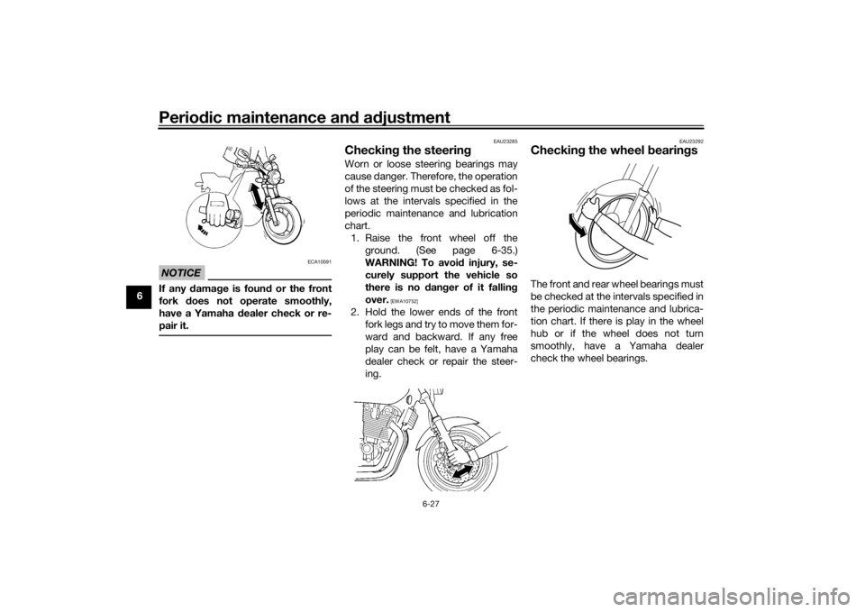
2. Hold the lower ends of the front fork legs and try to move them for-
ward and backward. If any free
play can be felt, have a Yamaha
dealer check or repair the steer-
ing.
EAU23292
Checkin g the wheel b earingsThe front and rear wheel bearings must
be checked at the intervals specified in
the periodic maintenance and lubrica-
tion chart. If there is play in the wheel
hub or if the wheel does not turn
smoothly, have a Yamaha dealer
check the wheel bearings.
U2PNE1E0.book Page 27 Monday, December 28, 2015 11:03 AM
Page 80 of 98

Periodic maintenance an d a djustment
6-35
6
EAU24351
Supportin g the motorcycleSince this model is not equipped with a
centerstand, follow these precautions
when removing the front and rear
wheel or performing other mainte-
nance requiring the motorcycle to
stand upright. Check that the motorcy-
cle is in a stable and level position be-
fore starting any maintenance. A
strong wooden box can be placed un-
der the engine for added stability.
To service the front wheel
1. Stabilize the rear of the motorcy- cle by using a motorcycle stand
or, if an additional motorcycle
stand is not available, by placing a
jack under the frame in front of the
rear wheel.
2. Raise the front wheel off the ground by using a motorcycle
stand.
To service the rear wheel
Raise the rear wheel off the ground by
using a motorcycle stand or, if a motor-
cycle stand is not available, by placing a jack either under each side of the
frame in front of the rear wheel or under
each side of the swingarm.
EAU24361
Front wheel
EAU65461
To remove the front wheel
WARNING
EWA10822
To avoi
d injury, securely support the
vehicle so there is no dan ger of it
fallin g over.1. Loosen the front wheel axle pinch
bolt, then the wheel axle and the
brake caliper bolts.1. Brake caliper bolt
2. Front wheel axle pinch bolt
3. Wheel axle
3
2
1
U2PNE1E0.book Page 35 Monday, December 28, 2015 11:03 AM
Page 81 of 98
Periodic maintenance an d a djustment
6-36
6
2. Lift the front wheel off the ground
according to the procedure in the
previous section “Supporting the
motorcycle”.
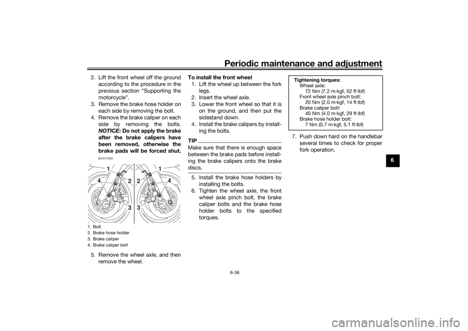
3. Remove the brake hose holder on each side by removing the bolt.
4. Remove the brake caliper on each side by removing the bolts.
NOTICE: Do not apply the brake
after the brake calipers have
b een removed , otherwise the
b rake pad s will be force d shut.
[ECA11052]
5. Remove the wheel axle, and then
remove the wheel. To install the front wheel
1. Lift the wheel up between the fork legs.
2. Insert the wheel axle.
3. Lower the front wheel so that it is on the ground, and then put the
sidestand down.
4. Install the brake calipers by install- ing the bolts.
TIPMake sure that there is enough space
between the brake pads before install-
ing the brake calipers onto the brake
discs.5. Install the brake hose holders byinstalling the bolts.
6. Tighten the wheel axle, the front wheel axle pinch bolt, the brake
caliper bolts and the brake hose
holder bolts to the specified
torques. 7. Push down hard on the handlebar
several times to check for proper
fork operation.
1. Bolt
2. Brake hose holder
3. Brake caliper
4. Brake caliper bolt
1
4
23
1
4
23
Tightenin g torques:
Wheel axle:
72 Nm (7.2 m·kgf, 52 ft·lbf)
Front wheel axle pinch bolt:
20 Nm (2.0 m·kgf, 14 ft·lbf)
Brake caliper bolt: 40 Nm (4.0 m·kgf, 29 ft·lbf)
Brake hose holder bolt: 7 Nm (0.7 m·kgf, 5.1 ft·lbf)
U2PNE1E0.book Page 36 Monday, December 28, 2015 11:03 AM
Page 82 of 98
Periodic maintenance an d a djustment
6-37
6
EAU25081
Rear wheel
EAU65470
To remove the rear wheel
WARNING
EWA10822
To avoi d injury, securely support the
vehicle so there is no dan ger of it
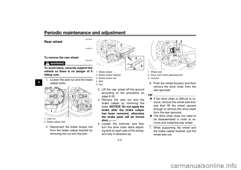
fallin g over.1. Loosen the axle nut and the brake
caliper bolts.
2. Disconnect the brake torque rod from the brake caliper bracket by
removing the nut and the bolt. 3. Lift the rear wheel off the ground
according to the procedure on
page 6-35.
4. Remove the axle nut and the brake caliper by removing the
bolts. NOTICE: Do not apply the
b rake after the brake caliper
has been removed , otherwise
the brake pa ds will be forced
shut.
[ECA11302]
5. Loosen the locknuts, and then turn the drive chain slack adjust-
ing bolt on each side of the swing-
arm fully in direction (a). 6. Push the wheel forward, and then
remove the drive chain from the
rear sprocket.
TIPIf the drive chain is difficult to re-
move, remove the wheel axle first,
and then lift the wheel upward
enough to remove the drive chain
from the rear sprocket.
The drive chain does not need to
be disassembled in order to re-
move and install the rear wheel.7. While supporting the wheel and
the brake caliper bracket, pull the
wheel axle out.
1. Axle nut
2. Brake caliper bolt
1 2
1. Brake caliper
2. Brake caliper bracket
3. Brake torque rod
4. Bolt
5. Nut
3
5
4
12
1. Wheel axle
2. Drive chain slack adjusting bolt
3. Locknut
123
(a)
U2PNE1E0.book Page 37 Monday, December 28, 2015 11:03 AM
Page 83 of 98

Periodic maintenance an d a djustment
6-38
6
8. Remove the brake caliper bracket
and the wheel.
To install the rear wheel 1. Place the wheel and the brake cal- iper bracket in the original posi-
tion.
2. Insert the wheel axle through the brake caliper bracket and wheel
from the right-hand side, and then
install the axle nut.
3. Install the drive chain onto the rear sprocket.
4. Connect the brake torque rod to the brake caliper bracket by in-
stalling the bolt and the nut.
5. Install the brake caliper by install- ing the bolts.
TIPMake sure that there is enough space
between the brake pads before install-
ing the brake caliper onto the brake
disc.6. Lower the rear wheel so that it ison the ground, and then put the
sidestand down.
7. Adjust the drive chain slack. (See page 6-22.) 8. Tighten the axle nut, brake caliper
bolts and brake torque rod nut to
the specified torques.
EAU25852
Trou bleshootin gAlthough Yamaha motorcycles receive
a thorough inspection before shipment
from the factory, trouble may occur
during operation. Any problem in the
fuel, compression, or ignition systems,
for example, can cause poor starting
and loss of power.
The following troubleshooting chart
represents a quick and easy procedure
for checking these vital systems your-
self. However, should your motorcycle
require any repair, take it to a Yamaha
dealer, whose skilled technicians have
the necessary tools, experience, and
know-how to service the motorcycle
properly.
Use only genuine Yamaha replace-
ment parts. Imitation parts may look
like Yamaha parts, but they are often
inferior, have a shorter service life and
can lead to expensive repair bills.
WARNING
EWA15142
When checkin g the fuel system, d o
not smoke, an d make sure there are
no open flames or sparks in the ar-
ea, inclu din g pilot li ghts from water
Ti ghtenin g torques:
Axle nut: 150 Nm (15 m·kgf, 108 ft·lbf)
Brake caliper bolt:
40 Nm (4.0 m·kgf, 29 ft·lbf)
Brake torque rod nut: 23 Nm (2.3 m·kgf, 17 ft·lbf)
U2PNE1E0.book Page 38 Monday, December 28, 2015 11:03 AM
Page 86 of 98
Motorcycle care and stora ge
7-1
7
EAU37834
Matte color cautionNOTICE
ECA15193
Some mo dels are equipped with
matte colore d finishe d parts. Be
sure to consult a Yamaha d ealer for
a d vice on what prod ucts to use be-
fore cleanin g the vehicle. Usin g a
b rush, harsh chemical prod ucts or
cleanin g compoun ds when cleanin g
these parts will scratch or damag e
their surface. Wax also shoul d not
b e applied to any matte colore d fin-
ishe d parts.
EAU26015
CareWhile the open design of a motorcycle
reveals the attractiveness of the tech-
nology, it also makes it more vulnera-
ble. Rust and corrosion can develop
even if high-quality components are
used. A rusty exhaust pipe may go un-
noticed on a car, however, it detracts
from the overall appearance of a mo-
torcycle. Frequent and proper care
does not only comply with the terms of
the warranty, but it will also keep your
motorcycle looking good, extend its
life and optimize its performance.
Before cleanin g
1. Cover the muffler outlet with a plastic bag after the engine has
cooled down.
2. Make sure that all caps and cov- ers as well as all electrical cou-
plers and connectors, including
the spark plug caps, are tightly in-
stalled.
3. Remove extremely stubborn dirt, like oil burnt onto the crankcase,
with a degreasing agent and a
brush, but never apply such prod- ucts onto seals, gaskets, sprock-
ets, the drive chain and wheel
axles. Always rinse the dirt and
degreaser off with water.
Cleanin g
NOTICE
ECA10773
Avoi d using strong aci dic wheel
cleaners, especially on spoke d
wheels. If such prod ucts are
use d on har d-to-remove dirt, do
not leave the cleaner on the af-
fected area any lon ger than in-
structed . Also, thorou ghly rinse
the area off with water, imme di-
ately dry it, an d then apply a cor-
rosion protection spray.
Improper cleanin g can d amage
plastic parts (such as cowlin gs,
panels, win dshiel ds, hea dlig ht
lenses, meter lenses, etc.) an d
the mufflers. Use only a soft,
clean cloth or spon ge with wa-
ter to clean plastic. However, if
the plastic parts cannot b e thor-
ou ghly cleaned with water, di-
lute d mil d d eter gent with water
may be used . Be sure to rinse
U2PNE1E0.book Page 1 Monday, December 28, 2015 11:03 AM
Page 87 of 98
Motorcycle care and stora ge
7-2
7
off any
deter gent resi due usin g
plenty of water, as it is harmful
to plastic parts.
Do not use any harsh chemical
prod ucts on plastic parts. Be
sure to avoi d usin g cloths or
spon ges which have b een in
contact with stron g or a brasive
cleanin g prod ucts, solvent or
thinner, fuel ( gasoline), rust re-
movers or inhi bitors, brake flui d,
antifreeze or electrolyte.
Do not use hi gh-pressure wash-
ers or steam-jet cleaners since
they cause water seepag e and
d eterioration in the followin g ar-
eas: seals (of wheel an d swin g-
arm bearin gs, fork an d b rakes),
electric components (couplers,
connectors, instruments,
switches an d li ghts), breather
hoses an d vents.
For motorcycles equippe d with
a win dshiel d: Do not use stron g
cleaners or har d spon ges as
they will cause dullin g or
sc r
atchin g. Some cleanin g
compoun ds for plastic may
leave scratches on the win d- shiel
d. Test the pro duct on a
small hi dden part of the win d-
shiel d to make sure that it does
not leave any marks. If the win d-
shiel d is scratche d, use a quality
plastic polishin g compoun d af-
ter washing .
After normal useRemove dirt with warm water, a mild
detergent, and a soft, clean sponge,
and then rinse thoroughly with clean
water. Use a toothbrush or bottlebrush
for hard-to-reach areas. Stubborn dirt
and insects will come off more easily if
the area is covered with a wet cloth for
a few minutes before cleaning.
After riding in the rain, near the sea oron salt-sprayed roadsSince sea salt or salt sprayed on roads
during winter are extremely corrosive
in combination with water, carry out
the following steps after each ride in
the rain, near the sea or on salt-
sprayed roads.
TIPSalt sprayed on roads in the winter
may remain well into spring.1. Clean the motorcycle with cold
water and a mild detergent, after
the engine has cooled down.
NOTICE: Do not use warm wa-
ter since it increases the corro-
sive action of the salt.
[ECA10792]
2. Apply a corrosion protection spray on all metal, including chrome-
and nickel-plated, surfaces to pre-
vent corrosion.
After cleanin g
1. Dry the motorcycle with a chamois or an absorbing cloth.
2. Immediately dry the drive chain and lubricate it to prevent it from
rusting.
3. Use a chrome polish to shine chrome, aluminum and stainless-
steel parts, including the exhaust
system. (Even the thermally in-
duced discoloring of stainless-
steel exhaust systems can be re-
moved through polishing.)
U2PNE1E0.book Page 2 Monday, December 28, 2015 11:03 AM