2016 YAMAHA WR 450F Spark plug cap
[x] Cancel search: Spark plug capPage 138 of 426

ELECTRICAL SYSTEM
3-40
EAS2GC1130
ELECTRICAL SYSTEM
EAS2GC1131CHECKING THE SPARK PLUG
1. Remove:• Seat
• Air scoop (left/right)
Refer to “GENERAL CHASSIS” on page 5-
1.
• Fuel tank “1” Refer to “FUEL TANK” on page 8-1.
ECA
NOTICE
Do not use too much force to pull the hose.
TIP
Remove the fuel tank, turn this 180 ° clockwise,
and put it in the frame “2” as shown.
2. Remove:• Spark plug cap
• Spark plugRefer to “CAMSHAFT” on page 6-11.
ECA
NOTICE
In order not to allow the dirt accumulated
around the spark plug to drop from the
spark plug hole into the cylinder, clean it be-
fore removing the spark plug.
3. Check:• Spark plug type
Wrong type Replace.
4. Check: • ElectrodeDamage/wear Replace the spark plug.
• Insulator Abnormal color Replace the spark plug.
Normal color is medium-to-light tan. 5. Clean:
• Spark plug(with a spark plug cleaner or a wire brush)
6. Measure: • Spark plug gap “a”Out of specification Adjust the spark plug
gap.
7. Install: • Spark plug
TIP
Before installing the spark plug, clean the spark
plug and gasket surface.
8. Install:• Spark plug cap
• Fuel tank
• Air scoop (left/right)
• Seat
• Side cover (left/right)Refer to “GENERAL CHASSIS” on page 5-
1.
EAS2GC1132CHECKING THE IGNITION TIMING
1. Remove:
• Timing mark accessing screw “1”
Manufacturer/model
NGK/CR8E
1
1
2
Spark plug gap 0.7–0.8 mm (0.028–0.031 in)
Spark plug 13 Nm (1.3 m·kgf, 9.4 ft·lbf)
T R..
1
Page 244 of 426

CAMSHAFT
6-17
▲▲▲▲▲▲▲▲▲▲▲▲▲▲▲▲▲▲▲▲▲▲▲▲▲▲▲▲▲▲▲▲
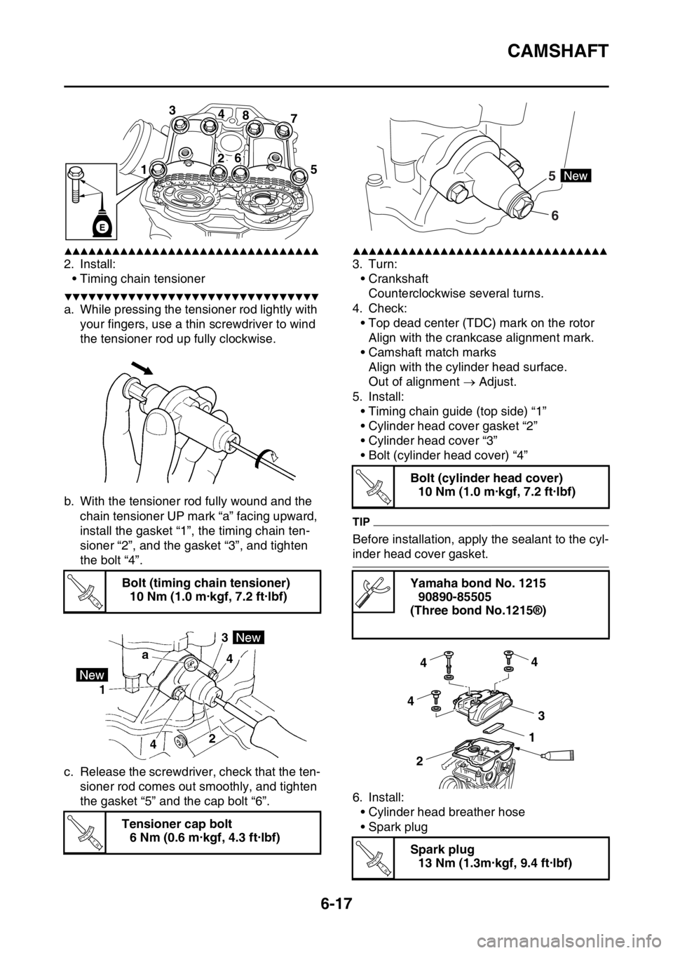
2. Install:• Timing chain tensioner
▼▼▼▼▼▼▼▼▼▼▼▼▼▼▼▼▼▼▼▼▼▼▼▼▼▼▼▼▼▼▼▼
a. While pressing the tensioner rod lightly with
your fingers, use a thin screwdriver to wind
the tensioner rod up fully clockwise.
b. With the tensioner rod fully wound and the chain tensioner UP mark “a” facing upward,
install the gasket “1”, the timing chain ten-
sioner “2”, and the gasket “3”, and tighten
the bolt “4”.
c. Release the screwdriver, check that the ten- sioner rod comes out smoothly, and tighten
the gasket “5” and the cap bolt “6”.
▲▲▲▲▲▲▲▲▲▲▲▲▲▲▲▲▲▲▲▲▲▲▲▲▲▲▲▲▲▲▲▲
3. Turn:• Crankshaft
Counterclockwise several turns.
4. Check: • Top dead center (TDC) mark on the rotor
Align with the crankcase alignment mark.
• Camshaft match marks Align with the cylinder head surface.
Out of alignment Adjust.
5. Install: • Timing chain guide (top side) “1”
• Cylinder head cover gasket “2”
• Cylinder head cover “3”
• Bolt (cylinder head cover) “4”
TIP
Before installation, apply the sealant to the cyl-
inder head cover gasket.
6. Install:• Cylinder head breather hose
• Spark plug
Bolt (timing chain tensioner)
10 Nm (1.0 m·kgf, 7.2 ft·lbf)
Tensioner cap bolt 6 Nm (0.6 m·kgf, 4.3 ft·lbf)
3 48
7
1 5
26
E
T R..
T R..
Bolt (cylinder head cover)
10 Nm (1.0 m·kgf, 7.2 ft·lbf)
Yamaha bond No. 1215 90890-85505
(Three bond No.1215®)
Spark plug 13 Nm (1.3m·kgf, 9.4 ft·lbf)
6
5
T R..
4
4
4 3
2 1
T R..
Page 330 of 426

ELECTRICAL COMPONENTS....................................................................... 9-60
CHECKING THE SWITCHES .................................................................. 9-64
CHECKING THE BULBS AND BULB SOCKETS .................................... 9-67
CHECKING THE FUSES ......................................................................... 9-68
CHECKING AND CHARGING THE BATTERY ........................................ 9-69
CHECKING THE RELAYS ....................................................................... 9-72
CHECKING THE DIODE .......................................................................... 9-73
CHECKING THE IGNITION SPARK GAP................................................ 9-73
CHECKING THE SPARK PLUG CAP ...................................................... 9-73
CHECKING THE IGNITION COIL ............................................................ 9-74
CHECKING THE CRANKSHAFT POSITION SENSOR........................... 9-74
CHECKING THE LEAN ANGLE SENSOR............................................... 9-75
CHECKING THE STARTER MOTOR OPERATION ................................ 9-75
CHECKING THE STATOR COIL ............................................................. 9-76
CHECKING THE RECTIFIER/REGULATOR ........................................... 9-76
CHECKING THE SPEED SENS OR ......................................................... 9-77
CHECKING THE FUEL SENDER ............................................................ 9-77
CHECKING THE RESISTER ................................................................... 9-77
CHECKING THE RADIATOR FAN MOTOR ............................................ 9-78
CHECKING THE COOLANT TEMPERATURE SENSOR........................ 9-78
CHECKING THE THROTTLE POSITION SENSOR ................................ 9-79
CHECKING THE THROTTLE POSITION SENSOR INPUT VOLTAGE .. 9-79
CHECKING THE INTAKE AIR PR ESSURE SENSOR ............................ 9-80
CHECKING THE INTAKE AIR TEMPERATURE SENSOR ..................... 9-80
CHECKING THE FUEL INJECTOR ......................................................... 9-81
Page 403 of 426

ELECTRICAL COMPONENTS
9-73
EAS2GC1388CHECKING THE DIODE
1. Check:•DiodeOut of specification Replace.
TIP
The pocket tester and the analog pocket tester
readings are shown in the following table.
▼▼▼▼▼▼▼▼▼▼▼▼▼▼▼▼▼▼▼▼▼▼▼▼▼▼▼▼▼▼▼▼
a. Disconnect the diode from the wire harness.
b. Connect the pocket tester ( 1) to the di-
ode coupler as shown.
c. Check the diode for continuity.
d. Check the diode for no continuity.
▲▲▲▲▲▲▲▲▲▲▲▲▲▲▲▲▲▲▲▲▲▲▲▲▲▲▲▲▲▲▲▲
EAS2GC1389CHECKING THE IGNITION SPARK GAP
1. Check: • Ignition spark gapOut of specification Perform the ignition
system troubleshooting, starting with step 4.
Refer to “TROUBLESHOOTING” on page 9-
4.
TIP
If the ignition spark gap is within specification,
the ignition system circui t is operating normally.
▼▼▼▼▼▼▼▼▼▼▼▼▼▼▼▼▼▼▼▼▼▼▼▼▼▼▼▼▼▼▼▼
a. Remove the spark plug cap from the spark
plug.
b. Connect the ignition checker “1” as shown.
c. Push the engine stop switch.
d. Measure the ignition spark gap “a”.
e. Crank the engine by pushing the start switch and gradually increase the spark gap until a
misfire occurs.
▲▲▲▲▲▲▲▲▲▲▲▲▲▲▲▲▲▲▲▲▲▲▲▲▲▲▲▲▲▲▲▲
EAS2GC1390CHECKING THE SPARK PLUG CAP
1. Remove:• Spark plug cap
(from the spark plug lead)
2. Check: • Spark plug cap resistance
Out of specification Replace.
Result
Continuity
(between “3” to “4”)
Pocket tester 90890-03112
Analog pocket tester YU-03112-C
No continuity Tester positive lead Sky blue
“1”
Tester negative lead Green/
Black “2”
Continuity Tester positive lead Green/
Black “2”
Tester negative lead Sky blue
“1”
No continuity Tester positive lead Red “3”
Tester negative lead Red/Blue
“4”
Continuity Tester positive lead Red/Blue
“4”
Tester negative lead Red “3”
2
1
4
3
R
Sb
G/B R/L
Minimum ignition spark gap 6.0 mm (0.24 in)
Ignition checker 90890-06754
Oppama pet–4000 spark checker YM-34487
2. Spark plug cap
Resistance 7.50–12.50 k
Page 404 of 426

ELECTRICAL COMPONENTS
9-74
▼▼▼▼▼▼▼▼▼▼▼▼▼▼▼▼▼▼▼▼▼▼▼▼▼▼▼▼▼▼▼▼
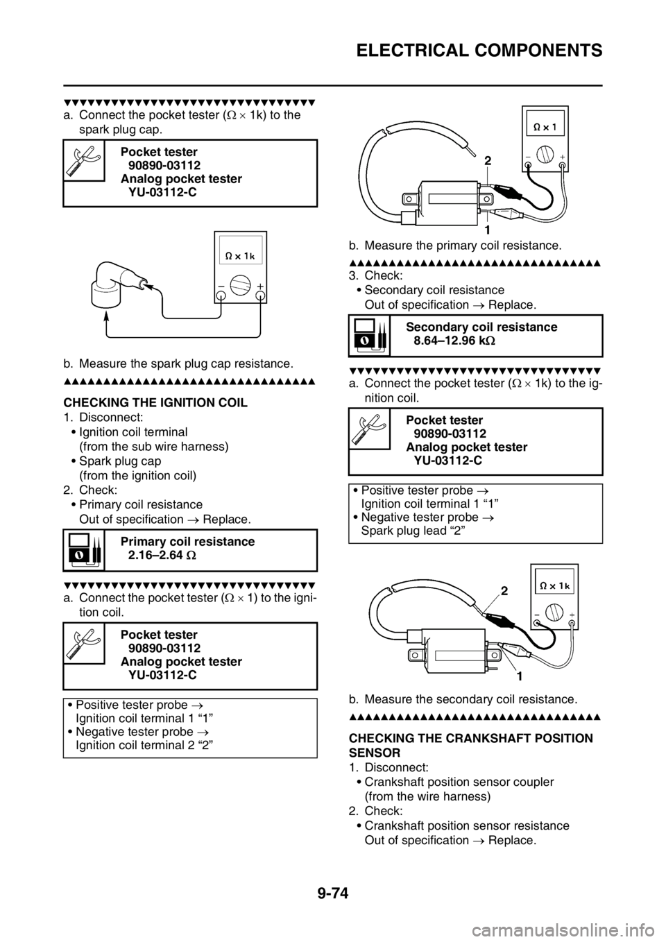
a. Connect the pocket tester ( 1k) to the
spark plug cap.
b. Measure the spark plug cap resistance.
▲▲▲▲▲▲▲▲▲▲▲▲▲▲▲▲▲▲▲▲▲▲▲▲▲▲▲▲▲▲▲▲
EAS2GC1391CHECKING THE IGNITION COIL
1. Disconnect: • Ignition coil terminal(from the sub wire harness)
• Spark plug cap (from the ignition coil)
2. Check:
• Primary coil resistanceOut of specification Replace.
▼▼▼▼▼▼▼▼▼▼▼▼▼▼▼▼▼▼▼▼▼▼▼▼▼▼▼▼▼▼▼▼
a. Connect the pocket tester ( 1) to the igni-
tion coil. b. Measure the primary coil resistance.
▲▲▲▲▲▲▲▲▲▲▲▲▲▲▲▲▲▲▲▲▲▲▲▲▲▲▲▲▲▲▲▲
3. Check:
• Secondary coil resistanceOut of specification Replace.
▼▼▼▼▼▼▼▼▼▼▼▼▼▼▼▼▼▼▼▼▼▼▼▼▼▼▼▼▼▼▼▼
a. Connect the pocket tester ( 1k) to the ig-
nition coil.
b. Measure the secondary coil resistance.
▲▲▲▲▲▲▲▲▲▲▲▲▲▲▲▲▲▲▲▲▲▲▲▲▲▲▲▲▲▲▲▲
EAS2GC1392CHECKING THE CRANKSHAFT POSITION
SENSOR
1. Disconnect: • Crankshaft position sensor coupler(from the wire harness)
2. Check:
• Crankshaft position sensor resistanceOut of specification Replace.
Pocket tester
90890-03112
Analog pocket tester YU-03112-C
Primary coil resistance 2.16–2.64
Pocket tester 90890-03112
Analog pocket tester YU-03112-C
• Positive tester probe
Ignition coil terminal 1 “1”
• Negative tester probe
Ignition coil terminal 2 “2”
Secondary coil resistance 8.64–12.96 k
Pocket tester 90890-03112
Analog pocket tester YU-03112-C
• Positive tester probe Ignition coil terminal 1 “1”
• Negative tester probe
Spark plug lead “2”
Page 415 of 426

TROUBLESHOOTING
10-2
Electrical system
1. Battery• Discharged battery
• Faulty battery
2. Spark plug • Incorrect spark plug gap
• Incorrect spark plug heat range
• Fouled spark plug
• Worn or damaged electrode
• Worn or damaged insulator
• Faulty spark plug cap
3. Ignition coil
• Broken or shorted primary or secondary coil
• Cracked or broken ignition coil
4. Ignition system • Faulty ECU
• Faulty crankshaft position sensor
• Broken generator rotor woodruff key
EAS2GC1410POOR MEDIUM-AND-HIGH-SPEED PER-
FORMANCE
Refer to “STARTING FAILURES” on page 10-
1.
Engine
1. Air filter
• Clogged air filter element
Fuel system
1. Fuel pump • Faulty fuel pump
2. Throttle body
• Defective throttle body
3. ECU • Faulty ECU
EAS2GC1411SHIFTING IS DIFFICULT
Refer to “CLUTCH” on page 6-41.
EAS2GC1412SHIFT PEDAL DOES NOT MOVE
Engine
1. Shift shaft
• Bent shift shaft
2. Shift drum and shift forks • Foreign object in a shift drum groove
• Seized shift fork
• Bent shift fork guide bar
3. Transmission
• Seized transmission gear
• Foreign object between transmission gears
• Improperly assembled transmission
EAS2GC1413
JUMPS OUT OF GEAR
Engine
1. Shift shaft• Incorrect shift pedal position
• Improperly returned stopper lever
2. Shift forks
• Worn shift fork
3. Shift drum • Incorrect axial play
• Worn shift drum groove
4. Transmission • Worn gear dog
EAS2GC1414CLUTCH SLIPS
Engine
1. Clutch• Improperly assembled clutch
• Loose or fatigued clutch spring
• Worn friction plate
• Worn clutch plate
2. Engine oil
• Incorrect oil level
• Incorrect oil viscosity (low)
• Deteriorated oil
EAS2GC1415CLUTCH DRAGS
Engine
1. Clutch• Unevenly tensioned clutch springs
• Warped pressure plate
• Bent clutch plate
• Swollen friction plate
• Bent clutch push rod
• Damaged clutch boss
• Burnt primary driven gear bushing
2. Engine oil • Incorrect oil level
• Incorrect oil viscosity (high)
• Deteriorated oil
EAS2GC1416OVERHEATING
Engine
1. Cylinder head and piston• Heavy carbon buildup
• Clogged coolant passages
2. Engine oil
• Incorrect oil level
• Incorrect oil viscosity
• Inferior oil quality
Page 416 of 426

TROUBLESHOOTING
10-3
Cooling system
1. Coolant• Low coolant level
2. Radiator • Damaged or leaking radiator
• Faulty radiator cap
• Bent or damaged radiator fin
3. Water pump • Damaged or faulty water pump
• Damaged hose
• Improperly connected hose
• Damaged pipe
• Improperly connected pipe
Fuel system
1. Throttle body • Damaged or loose throttle body joint
2. Air filter • Clogged air filter element
Chassis
1. Brake(s) • Dragging brake
Electrical system
1. Spark plug • Incorrect spark plug gap
• Incorrect spark plug heat range
2. Ignition system • Faulty ECU
• Faulty coolant temperature sensor
EAS2GC1417OVERCOOLING
Cooling system
1. Coolant temperature sensor• Faulty coolant temperature sensor
EAS2GC1418POOR BRAKING PERFORMANCE
Chassis
1. Brake(s)• Worn brake pad
• Worn brake disc
• Air in hydraulic brake system
• Leaking brake fluid
• Defective master cylinder kit
• Faulty brake caliper kit
• Faulty brake caliper seal
• Loose union bolt
• Damaged brake hose
• Oil or grease on the brake disc
• Oil or grease on the brake pad
• Incorrect brake fluid level
EAS2GC1419FRONT FORK OIL LEAKING
Chassis
1. Front fork• Bent, damaged, or rusty inner tube
• Cracked or damaged outer tube
• Improperly installed oil seal
• Damaged oil seal lip
• Incorrect oil level (high)
• Loose damper rod assembly bolt
• Damaged damper rod assembly bolt copper
washer
• Cracked or damaged cap bolt O-ring
EAS2GC1420FAULTY FRONT FORK LEGS
Chassis
1. Front fork • Bent or damaged inner tube
• Bent or damaged outer tube
• Broken fork spring
• Bent or damaged damper rod
• Incorrect oil viscosity
• Incorrect oil level
EAS2GC1421UNSTABLE HANDLING
Chassis
1. Handlebar• Bent or improperly installed handlebar
2. Steering head components • Improperly installed upper bracket
• Improperly installed lower bracket(improperly tightened ring nut)
• Bent steering stem
• Damaged ball bearing or bearing race
3. Front fork leg (s) • Uneven oil levels (both front fork legs)
• Unevenly tensioned fork spring (both front fork legs)
• Broken fork spring
• Bent or damaged inner tube
• Bent or damaged outer tube
4. Swingarm • Worn bearing or bushing
• Bent or damaged swingarm
5. Rear shock absorber assembly (-ies) • Faulty rear shock absorber spring
• Leaking oil or gas
6. Tire (s) • Uneven tire pressures (front and rear)
• Incorrect tire pressure
• Uneven tire wear