Page 276 of 428
CLUTCH
6-47
6. Install:
• Bearing “1”
• Washer “2”
• Circlip “3”
To push rod 1 “4”.
TIP
Apply the engine oil on the bearing and washer.
7. Install:
• Push rod 2 “1”
•Ball “2”
• Push rod 1 “3”
TIP
Apply the engine oil on the push rod 1, 2 and
ball.
8. Install:
• Pressure plate “1”9. Install:
• Clutch spring
• Clutch spring bolt
TIP
Tighten the bolts in stages and in a crisscross
pattern.
10.Install:
• Gasket “1”
11.Install:
• Clutch cover “1”
• Clutch cover bolt
TIP
Tighten the bolts in stages and in a crisscross
pattern.
NewClutch spring bolt
10 Nm (1.0 m·kgf, 7.2 ft·lbf)
Clutch cover bolt
10 Nm (1.0 m·kgf, 7.2 ft·lbf)
T R..
1
2 3
45
New
T R..
1
Page 295 of 428

GENERATOR AND STARTER CLUTCH
6-66
2. Install:
• Washer
• Generator rotor nut “1”
TIP
Tighten the generator rotor nut to 65 Nm (6.5
m·kgf, 47 ft·lbf), loosen and retighten the gener-
ator rotor nut to 65 Nm (6.5 m·kgf, 47 ft·lbf).
3. Install:
• Starter idle gear shaft “1”
• Bearing “2”
• Starter idle gear 2 “3”
TIP
Apply the engine oil on the starter idle gear
shaft, bearing and idle gear inner circumfer-
ence.
4. Install:
• Dowel pin
• Crankcase cover gasket
• Left crankcase cover “1”
• Lead holder “2”
• Crankcase cover bolt
• Neutral switch lead “3”
TIP
• Pass the AC magneto lead “4” under the left
crankcase cover “a” as shown.
• Tighten the bolts in stage, using a crisscross
pattern.
5. Install:
• Washer “1”
• Damper assembly “2”
• Washer “3”
TIP
Apply the engine oil to the shaft and washers.
6. Install:
• Cover (damper assembly) “1”
• Bracket “2”
•Bolt “3”
• Breather hose 2 “4” Generator rotor nut
65 Nm (6.5 m·kgf, 47 ft·lbf)
Crankcase cover bolt
10 Nm (1.0 m·kgf, 7.2 ft·lbf)
T R..
1
1
21
2
3
New
T R..Bolt
10 Nm (1.0 m·kgf, 7.2 ft·lbf)
4
1a
1
2
3
21
2
3
T R..
Page 301 of 428

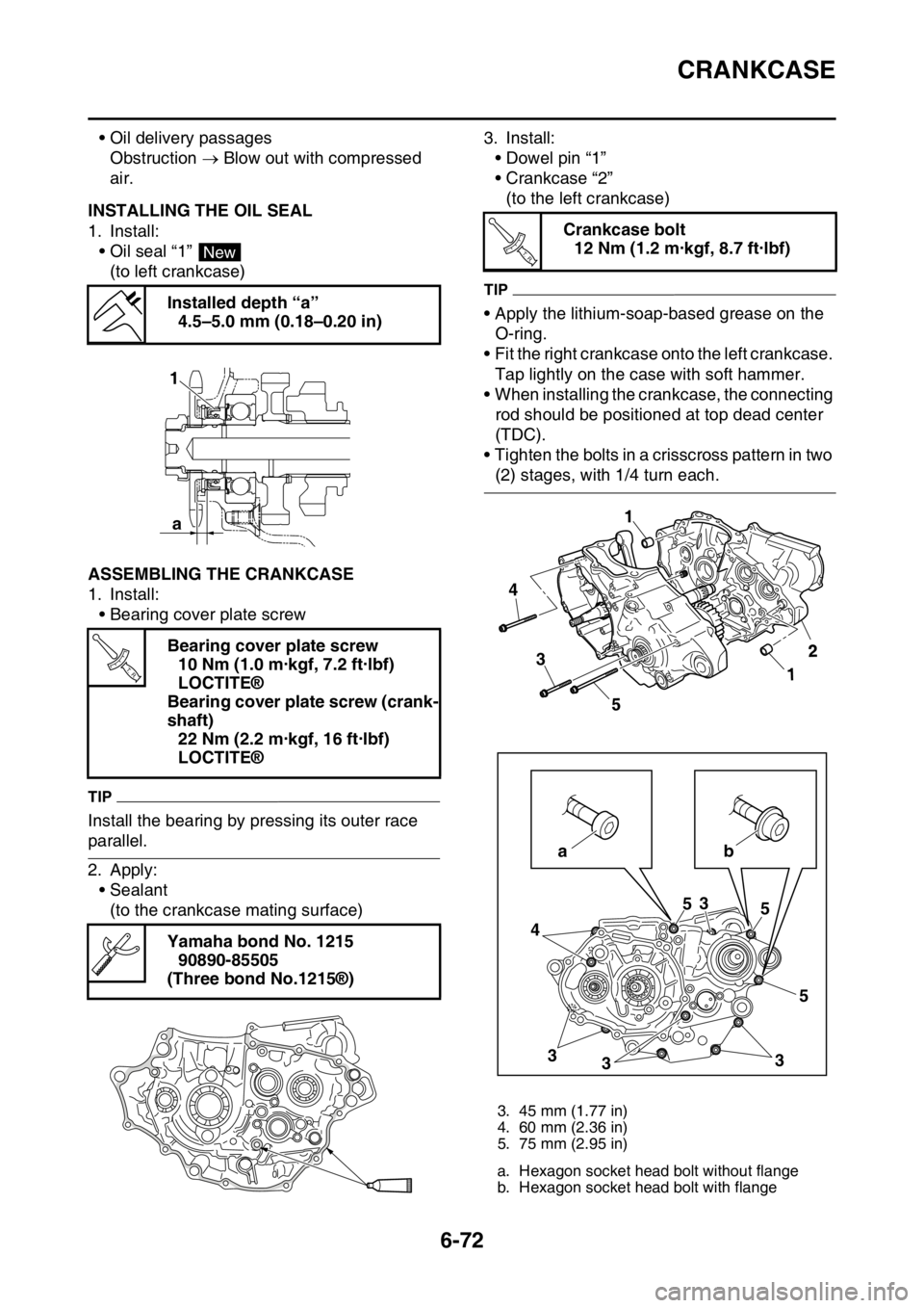
CRANKCASE
6-72
• Oil delivery passages
Obstruction Blow out with compressed
air.
EAS2GB7315INSTALLING THE OIL SEAL
1. Install:
• Oil seal “1”
(to left crankcase)
EAS2GB7316ASSEMBLING THE CRANKCASE
1. Install:
• Bearing cover plate screw
TIP
Install the bearing by pressing its outer race
parallel.
2. Apply:
• Sealant
(to the crankcase mating surface)3. Install:
• Dowel pin “1”
• Crankcase “2”
(to the left crankcase)
TIP
• Apply the lithium-soap-based grease on the
O-ring.
• Fit the right crankcase onto the left crankcase.
Tap lightly on the case with soft hammer.
• When installing the crankcase, the connecting
rod should be positioned at top dead center
(TDC).
• Tighten the bolts in a crisscross pattern in two
(2) stages, with 1/4 turn each. Installed depth “a”
4.5–5.0 mm (0.18–0.20 in)
Bearing cover plate screw
10 Nm (1.0 m·kgf, 7.2 ft·lbf)
LOCTITE®
Bearing cover plate screw (crank-
shaft)
22 Nm (2.2 m·kgf, 16 ft·lbf)
LOCTITE®
Yamaha bond No. 1215
90890-85505
(Three bond No.1215®)
New
a 1
T R..
Crankcase bolt
12 Nm (1.2 m·kgf, 8.7 ft·lbf)
3. 45 mm (1.77 in)
4. 60 mm (2.36 in)
5. 75 mm (2.95 in)
a. Hexagon socket head bolt without flange
b. Hexagon socket head bolt with flange
T R..
4
5
3
43
335 5 5
3
ab1
1
2