2016 YAMAHA GRIZZLY 350 brake light
[x] Cancel search: brake lightPage 56 of 146

6-4
61. Bring the ATV to a complete stop.
2. Apply the brake pedal.
3. Shift from neutral to reverse and vice versa by
moving the drive select lever along the shift
guide.
TIPWhen in reverse, the reverse indicator light should
come on. If the indicator light does not come on,
have a Yamaha dealer check the electrical circuit.
4. Check behind for people or obstacles, andthen release the brake pedal.
5. Open the throttle lever gradually and continue to watch to the rear while backing.EBU20683Engine break-inTIPFor ATVs equipped with an odometer or an hour
meter, follow the figures given in km (mi) or the
figures given in hours.
For ATVs not equipped with an odometer or
hour meter, follow the figures given in hours. There is never a more important period in the life
of your engine than the first 320 km (200 mi) or 20
hours of riding. For this reason, you should read
the following material carefully.
Since the engine is brand new, do not put an ex-
cessive load on it for the first 320 km (200 mi) or
20 hours. The various parts in the engine wear and
polish themselves to the correct operating clear-
ances. During this period, prolonged full-throttle
operation or any condition that might result in en-
gine overheating must be avoided.
1. Drive select lever
2. F (Forward)
3. N (Neutral)
4. R (Reverse)
1
F2
N3R4
U1NS64E0.book Page 4 Thursday, June 25, 2015 8:36 AM
Page 72 of 146

7-12
7Select a large, flat, unpaved area to become famil-
iar with your ATV. Make sure that this area is free
of obstacles and other riders. You should practice
control of the throttle, brakes, and turning techni-
ques in this area before trying more difficult ter-
rain.
Set the parking brake and follow the instruction on
page 6-1 to start the engine. Once it has warmed
up you are ready to begin riding your ATV. With
the engine idling, return the starter (choke) to the
closed position, and shift the drive select lever into
the forward position, and then release the parking
brake. Apply the throttle slowly and smoothly.
The centrifugal clutch will engage and you will
start to accelerate. If the throttle is applied too
abruptly, the front wheels may lift off the ground,
resulting in a loss of directional control. Avoid
higher speeds until you are thoroughly familiar
with the operation of your ATV.
When slowing down or stopping, release the
throttle and apply the brakes smoothly and evenly.
Improper use of the brakes can cause the tires to
lose traction, reducing control and increasing the
possibility of an accident. TURNING YOUR ATV
WARNING
EWB01772Always follow proper procedures for turning as
described in this Owner’s Manual. Practice
turning at low speeds before attempting to turn
at faster speeds. Do not turn at speeds too fast
for your skills or the conditions. ATV could go
out of control, causing a collision or overturn. To achieve maximum traction on unpaved surfac-
es, the two rear wheels turn together at the same
speed. Therefore, unless the wheel on the inside
of the turn is allowed to slip or lose some traction,
the ATV will resist turning. A special turning tech-
nique must be used to allow the ATV to make
turns quickly and easily. It is essential that this skill
be learned first at low speed.
As you approach a curve, slow down and begin to
turn the handlebars in the desired direction. As
you do so, put your weight on the footboard to the
outside of the turn (opposite your desired direc-
tion) and lean your upper body into the turn. Use
the throttle to maintain an even speed through the
turn. This maneuver will let the wheel on the inside
of the turn slip slightly, allowing the ATV to make
the turn properly.
U1NS64E0.book Page 12 Thursday, June 25, 2015 8:36 AM
Page 91 of 146

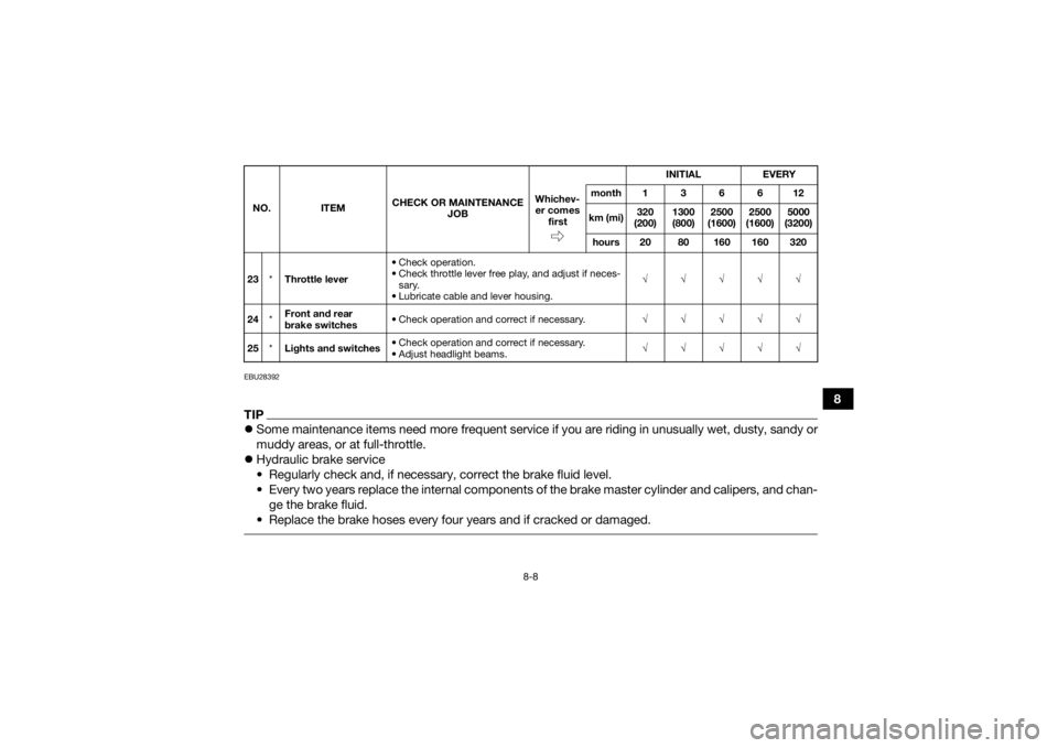
8-8
8
EBU28392TIPSome maintenance items need more frequent service if you are riding in unusually wet, dusty, sandy or
muddy areas, or at full-throttle.
Hydraulic brake service
• Regularly check and, if necessary, correct the brake fluid level.
• Every two years replace the internal components of the brake master cylinder and calipers, and chan-
ge the brake fluid.
• Replace the brake hoses every four years and if cracked or damaged. 23 *Throttle lever • Check operation.
• Check throttle lever free play, and adjust if neces-
sary.
• Lubricate cable and lever housing. √√√√√
24 *Front and rear
brake switches
• Check operation and correct if necessary.
√√√√√
25 *Lights and switches • Check operation and correct if necessary.
• Adjust headlight beams. √√√√√
NO. ITEM
CHECK OR MAINTENANCE
JOB INITIAL EVERY
Whichev- er comes first month136612
km (mi) 320
(200) 1300
(800) 2500
(1600) 2500
(1600) 5000
(3200)
hours 20 80 160 160 320U1NS64E0.book Page 8 Thursday, June 25, 2015 8:36 AM
Page 119 of 146

8-36
8
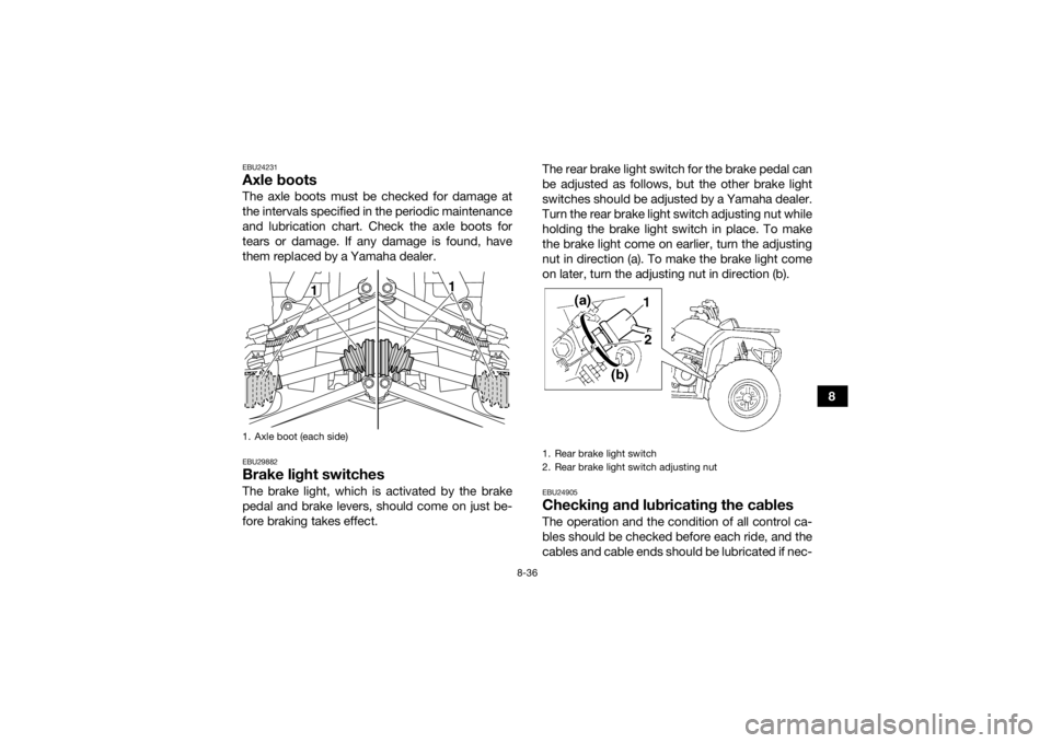
EBU24231Axle bootsThe axle boots must be checked for damage at
the intervals specified in the periodic maintenance
and lubrication chart. Check the axle boots for
tears or damage. If any damage is found, have
them replaced by a Yamaha dealer.EBU29882Brake light switchesThe brake light, which is activated by the brake
pedal and brake levers, should come on just be-
fore braking takes effect.The rear brake light switch for the brake pedal can
be adjusted as follows, but the other brake light
switches should be adjusted by a Yamaha dealer.
Turn the rear brake light switch adjusting nut while
holding the brake light switch in place. To make
the brake light come on earlier, turn the adjusting
nut in direction (a). To make the brake light come
on later, turn the adjusting nut in direction (b).
EBU24905Checking and lubricating the cablesThe operation and the condition of all control ca-
bles should be checked before each ride, and the
cables and cable ends should be lubricated if nec-
1. Axle boot (each side)
1
1
1. Rear brake light switch
2. Rear brake light switch adjusting nut
U1NS64E0.book Page 36 Thursday, June 25, 2015 8:36 AM
Page 129 of 146

8-46
8
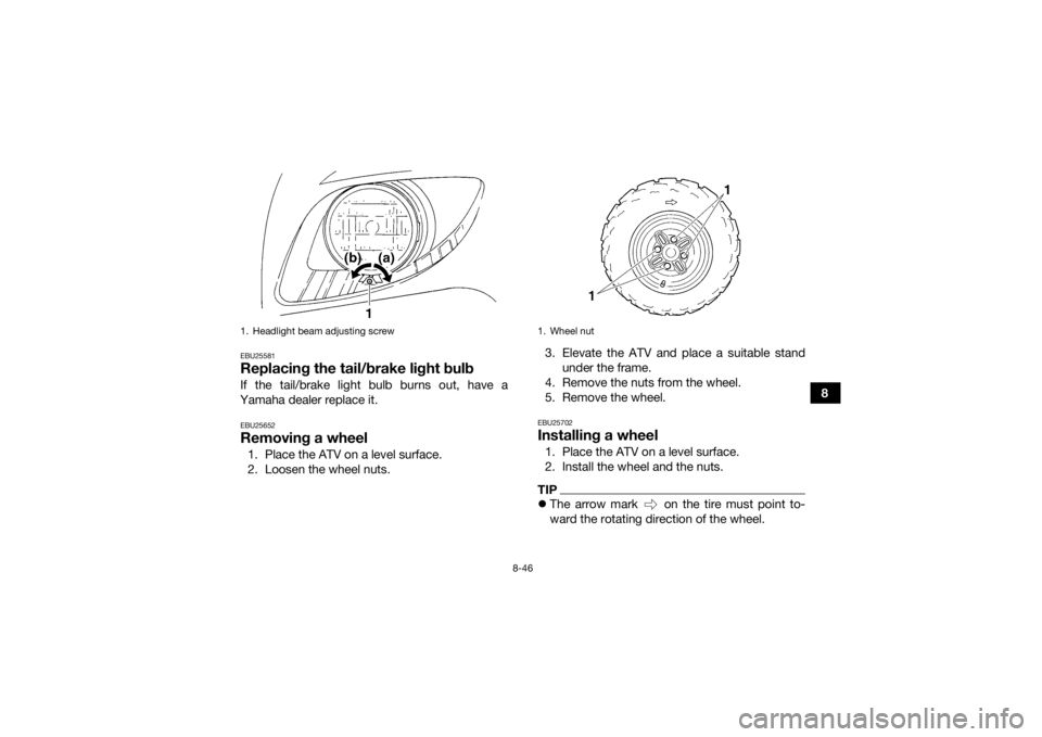
EBU25581Replacing the tail/brake light bulbIf the tail/brake light bulb burns out, have a
Yamaha dealer replace it.EBU25652Removing a wheel1. Place the ATV on a level surface.
2. Loosen the wheel nuts. 3. Elevate the ATV and place a suitable stand
under the frame.
4. Remove the nuts from the wheel.
5. Remove the wheel.
EBU25702Installing a wheel1. Place the ATV on a level surface.
2. Install the wheel and the nuts.TIP The arrow mark on the tire must point to-
ward the rotating direction of the wheel.
1. Headlight beam adjusting screw
1. Wheel nut
U1NS64E0.book Page 46 Thursday, June 25, 2015 8:36 AM
Page 139 of 146

10-4
10
Specified brake fluid:DOT 4Rear brake:Type:
Drum brake
Operation: Left hand and right foot operationFront suspension:Type:
Double wishbone
Spring/shock absorber type: Coil spring/oil damper
Wheel travel: 160 mm (6.3 in)Rear suspension:Type:Swingarm
Spring/shock absorber type: Coil spring/oil damper
Wheel travel:
180 mm (7.1 in)Electrical system:Ignition system:DC CDI
Charging system:
AC magnetoBattery:Model:YTX14AH
Voltage, capacity:
12 V, 12.0 Ah
Headlight:Bulb type:Krypton bulbBulb voltage, wattage × quantity:Headlight:
12 V, 30.0/30.0 W × 2
Tail/brake light: 12 V, 5.0/21.0 W × 1
Meter lighting:
14 V, 3.0 W × 1
Neutral indicator light: 12 V, 1.7 W × 1
Reverse indicator light: 12 V, 1.7 W × 1
Oil temperature warning light:
12 V, 1.7 W × 1
On-command four-wheel-drive indicator light: 12 V, 1.7 W × 1Fuses:Main fuse:
30.0 A
Headlight fuse: 15.0 A
Signaling system fuse: 10.0 A
Ignition fuse:
15.0 A
Auxiliary DC jack fuse: 10.0 A
Four-wheel-drive motor fuse: 3.0 A
U1NS64E0.book Page 4 Thursday, June 25, 2015 8:36 AM
Page 143 of 146

12-1
12
INDEX
AAccessories and loading ................................................ 6-6
Air filter element, cleaning ........................................... 8-19
Axle boots .................................................................... 8-36BBattery ......................................................................... 8-39
Brake fluid, changing ................................................... 8-30
Brake fluid level, checking ........................................... 8-29
Brake lever free play, checking the front ..................... 8-30
Brake lever, front ........................................................... 4-8
Brake levers, checking and lubricating ........................ 8-37
Brake light switches ..................................................... 8-36
Brake pads and shoes, checking ................................ 8-28
Brake pedal and rear brake lever ................................... 4-8
Brake pedal, checking and lubricating ........................ 8-38
Brakes .......................................................................... 8-27
Brakes, front and rear .................................................... 5-3CCables, checking and lubricating ................................ 8-36
Carburetor, adjusting ................................................... 8-25
Carrier, front ................................................................. 4-16
Carrier, rear .................................................................. 4-16
Chassis fasteners .......................................................... 5-6
Cleaning ......................................................................... 9-1DDifferential gear oil ......................................................... 5-3
Differential gear oil, changing ...................................... 8-18
Drive select lever ......................................................... 4-10
Drive select lever and driving in reverse ........................ 6-3Drive select lever safety system cable, adjusting ........ 8-27
EEngine break-in .............................................................. 6-4
Engine, cold start ........................................................... 6-1
Engine idling speed ..................................................... 8-25
Engine oil ....................................................................... 5-3
Engine oil and oil filter cartridge .................................. 8-11
Engine, starting a warm ................................................. 6-3
Engine stop switch ........................................................ 4-5FFinal gear oil ......................................................... 5-3, 8-15
Four-wheel-drive indicator light ..................................... 4-3
Fuel ....................................................................... 4-11, 5-3
Fuel cock ..................................................................... 4-12
Fuel tank cap ............................................................... 4-10
Fuses, replacing .......................................................... 8-42HHandlebar switches ....................................................... 4-5
Headlight beam, adjusting ........................................... 8-45
Headlight bulb, replacing ............................................. 8-44
Horn switch .................................................................... 4-5IIdentification numbers ................................................. 11-1
Indicator lights and warning light ................................... 4-2
Instruments, lights and switches ................................... 5-6LLabel locations ............................................................... 1-1
Light switch ................................................................... 4-5
U1NS64E0.book Page 1 Thursday, June 25, 2015 8:36 AM
Page 144 of 146

12-2
12
MMain switch .................................................................... 4-1
Maintenance and lubrication chart ................................8-5
Maintenance chart, emission control system ................ 8-3
Model label ................................................................... 11-1NNeutral indicator light .....................................................4-2OOil temperature warning light ......................................... 4-3
On-Command four-wheel-drive switch ......................... 4-6
Owner’s manual and tool kit .......................................... 8-2PParking ........................................................................... 6-5
Parking brake ................................................................. 4-9
Parking on a slope ......................................................... 6-5
Part locations ................................................................. 3-1RRear brake, adjusting the pedal height, and the pedal and lever free play ..................................................... 8-31
Reverse indicator light ................................................... 4-2
Riding your ATV ............................................................. 7-1SSafety information .......................................................... 2-1
Seat .............................................................................. 4-14
Shock absorber assemblies, adjusting the front .........4-17
Shock absorber assembly, adjusting the rear ............. 4-18
Spark arrester, cleaning ............................................... 8-22
Spark plug, checking .....................................................8-9
Specifications ............................................................... 10-1
Speed limiter .................................................................. 4-7
Speedometer ................................................................. 4-3 Starter (choke) .............................................................. 4-14
Start switch .................................................................... 4-5
Steering shaft, lubricating ............................................ 8-39
Storage .......................................................................... 9-2
Storage compartment .................................................. 4-15
TTail/brake light bulb, replacing ..................................... 8-46
Throttle lever .......................................................... 4-6, 5-4
Throttle lever free play, adjusting ................................. 8-26
Tires ............................................................................... 5-4
Troubleshooting ........................................................... 8-48
Troubleshooting chart .................................................. 8-49VValve clearance ............................................................ 8-27
V-belt case drain plug .................................................. 8-24
V-belt cooling duct check hose ................................... 8-24
Vehicle identification number ....................................... 11-1WWheel hub bearings, checking ..................................... 8-38
Wheel, installing ........................................................... 8-46
Wheel, removing .......................................................... 8-46
U1NS64E0.book Page 2 Thursday, June 25, 2015 8:36 AM