2016 YAMAHA FJR1300AS clutch
[x] Cancel search: clutchPage 5 of 126

Table of contents
Safety information ............................1-1
Description ........................................2-1
Left view ..........................................2-1
Right view........................................2-2
Controls and instruments ................2-3
Instrument an d control functions ....3-1
Immobilizer system .........................3-1
Main switch/steering lock ...............3-2
Indicator lights and warning lights ............................................3-4
Cruise control system .....................3-8
Multi-function meter unit ...............3-11
D-mode (drive mode) ....................3-23
Handlebar switches.......................3-24
YCC-S system...............................3-26
Shift pedal .....................................3-26
Hand shift lever .............................3-27
Brake lever ....................................3-28
Brake pedal ...................................3-28
ABS ...............................................3-29
Traction control system.................3-30
Fuel tank cap.................................3-31
Fuel................................................3-32
Fuel tank overflow hose ................3-33
Catalytic converters .....................3-34
Seats .............................................3-34
Adjusting the rider seat height ......3-36
Storage compartment ...................3-38
Accessory box...............................3-39
Adjusting the headlight beams......3-40
Handlebar position ........................3-40
Opening and closing the cowling vents ..........................................3-41
Rear view mirrors ..........................3-42
Adjusting the front and rear suspension.................................3-43
Sidestand ......................................3-47
Ignition circuit cut-off system........3-48
Auxiliary DC jack ...........................3-50
Cornering lights .............................3-51 For your safety – pre-operation
checks
............................................... 4-1
Operation an d important ri din g
points ................................................. 5-1
Starting the engine.......................... 5-2
Shifting ............................................ 5-3
Tips for reducing fuel consumption................................ 5-5
Engine break-in ............................... 5-6
Parking ............................................ 5-7
Perio dic maintenance an d
a d justment ........................................ 6-1
Owner’s tool kit ............................... 6-2
Periodic maintenance chart for the emission control system.............. 6-3
General maintenance and lubrication chart........................... 6-4
Removing and installing panels ...... 6-7
Checking the spark plugs ............. 6-10
Canister......................................... 6-11
Engine oil and oil filter cartridge ... 6-11
Final gear oil.................................. 6-14
Coolant ......................................... 6-15
Air filter element ............................ 6-17
Checking the engine idling
speed......................................... 6-17
Checking the throttle grip free
play ............................................ 6-18
Valve clearance ............................. 6-18
Tires .............................................. 6-19
Cast wheels .................................. 6-21
YCC-S clutch ................................ 6-22
Checking the brake lever free play ............................................ 6-22
Brake light switches ...................... 6-23
Checking the front and rear brake pads........................................... 6-23
Checking the brake and YCC-S clutch fluid levels ....................... 6-24
Changing the brake and YCC-S clutch fluids ............................... 6-26
Checking and lubricating the cables ........................................ 6-26
UB95E0E0.book Page 1 Friday, February 19, 2016 2:15 PM
Page 12 of 126

Description
2-1
2
EAU63371
Left view
12
3
4
65
789101112
1. Coolant reservoir (page 6-15)
2. Accessory box (page 3-39)
3. Owner’s tool kit (page 6-2)
4. Final gear oil filler bolt (page 6-14)
5. Final gear oil drain bolt (page 6-14)
6. YCC-S clutch fluid reservoir (page 6-24)
7. Air filter element (page 6-17)
8. Shift pedal (page 3-26)
9. Engine oil filler cap (page 6-11)
10.Engine oil filter cartridge (page 6-11)
11.Engine oil level check window (page 6-11)
12.Engine oil drain bolt (page 6-11)
UB95E0E0.book Page 1 Friday, February 19, 2016 2:15 PM
Page 20 of 126

Instrument and control functions
3-6
3 Try to reset the traction control system
and the lights by following the proce-
dures under “Resetting” on page 3-31.
EAU55392Electronically a
djusta ble suspen-
sion system warnin g lig ht “ ”
This warning light comes on if a prob-
lem is detected in the electronically ad-
justable suspension system.
The electrical circuit of the warning
light can be checked by turning the key
to “ON”. The warning light should
come on for a few seconds, and then
go off.
If the warning light does not come on
initially when the key is turned to “ON”,
or if the warning light remains on, have
a Yamaha dealer check the electrical
circuit.
EAU55431Shift down in dicator li ght “ ”
This indicator light flashes when the
transmission gear is too high for the
vehicle speed.
To avoid damaging the YCC-S clutch,
the shift down indicator light flashes
when it is necessary to downshift. If
this occurs, downshift until the indica-
tor light stops flashing.
EAU55442YCC-S system warnin g li ght “ ”
If this warning light comes on while rid-
ing, the YCC-S system may not work
correctly. If this occurs: It may be impossible to shift out of
the gear you are in.
The clutch may stay engaged, so
a shuddering sensation may be
felt as you come to a stop. Stop the vehicle when it is safe to do
so, and park it away from traffic. Have
a Yamaha dealer check the YCC-S
system.
TIP
In order to be able to move the vehicle
after it has stopped, if shifting is impos-
sible using the hand shift lever and shift
pedal, proceed as follows:
Place the vehicle on the centerstand,
then while rotating the rear wheel, push
the shift pedal rod and shift pedal rod
pivot forward until the transmission is
in the neutral position.
The electrical circuit of the warning
light can be checked by turning the key
to “ON”. The warning light should
come on for a few seconds, and then
go off.
If the warning light does not come on
initially when the key is turned to “ON”,
or if the warning light remains on, have
a Yamaha dealer check the electrical
circuit.
EAU55451Stop mo
de function in dicator
li g ht “ ”
This indicator light comes on when the
stop mode function is activated.
1. Shift pedal rod pivot
2. Shift pedal rod
1
2
UB95E0E0.book Page 6 Friday, February 19, 2016 2:15 PM
Page 27 of 126

Instrument and control functions
3-13
3
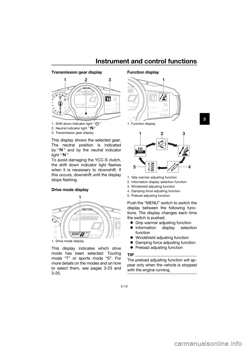
Transmission
gear display
This display shows the selected gear.
The neutral position is indicated
by “ ” and by the neutral indicator
light “ ”.
To avoid damaging the YCC-S clutch,
the shift down indicator light flashes
when it is necessary to downshift. If
this occurs, downshift until the display
stops flashing.
Drive mo de display
This display indicates which drive
mode has been selected: Touring
mode “T” or sports mode “S”. For
more details on the modes and on how
to select them, see pages 3-23 and
3-25. Function d
isplay
Push the “MENU” switch to switch the
display between the following func-
tions. The display changes each time
the switch is pushed. Grip warmer adjusting function
Information display selection
function
Windshield adjusting function
Damping force adjusting function
Preload adjusting function
TIP
The preload adjusting function will ap-
pear only when the vehicle is stopped
with the engine running.
1. Shift down indicator light “ ”
2. Neutral indicator light “ ”
3. Transmission gear display
1. Drive mode display
GEARN25A.TEMP ˚C
LoC.TEMP˚C
0:06TIME TRIP
213
GEAR
NA.TEMP
C.TEMP
1
1. Function display
1. Grip warmer adjusting function
2. Information display selection function
3. Windshield adjusting function
4. Damping force adjusting function
5. Preload adjusting function
GEAR
N
25A.TEMP˚C
LoC.TEMP˚C
0:06TIME TRIP
1
213
45
UB95E0E0.book Page 13 Friday, February 19, 2016 2:15 PM
Page 40 of 126

Instrument and control functions
3-26
3
EAU55491
YCC-S system
This vehicle features the YCC-S
(Yamaha Chip Controlled-Shift) sys-
tem.
The basic function of this system al-
lows the rider to shift gears without the
use of a clutch lever. Furthermore, a
hand shift lever is equipped on the
handlebar, allowing the rider to shift
gears with either the foot-operated
shift pedal or the hand-operated shift
lever. (See page 3-27.)
When the engine is started and the
shift pedal or the shift lever is moved, a
signal is sent to the MCU (Motor Con-
trol Unit) which disengages the clutch,
the ECU (Engine Control Unit) then ad-
justs the electronic throttle valve, the
gear shift is made and then the clutch
is re-engaged once the engine is run-
ning at the proper speed. Clutch en-
gagement is controlled optimally by
the MCU according to engine r/min,
engine requirements, and riding condi-
tions.
TIP
This is not an automatic transmission,
only the clutch system is automatic.
The gears must be shifted by the rider
except when stopping the vehicle
while the stop mode function is activat-
ed.
See “Stop mode function switch” (See
page 3-25.) and OPERATION AND IM-
PORTANT RIDING POINTS (See page
5-1.) for further explanation of this sys-
tem.
EAU40496
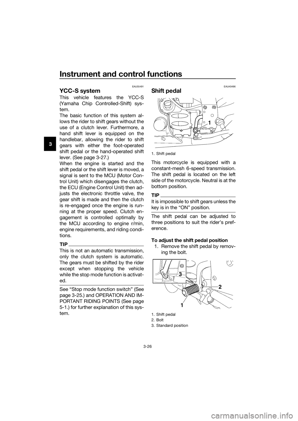
Shift pe dal
This motorcycle is equipped with a
constant-mesh 6-speed transmission.
The shift pedal is located on the left
side of the motorcycle. Neutral is at the
bottom position.
TIP
It is impossible to shift gears unless the
key is in the “ON” position.
The shift pedal can be adjusted to
three positions to suit the rider’s pref-
erence.
To a djust the shift ped al position
1. Remove the shift pedal by remov- ing the bolt.
1. Shift pedal
1. Shift pedal
2. Bolt
3. Standard position
3
1
2
UB95E0E0.book Page 26 Friday, February 19, 2016 2:15 PM
Page 66 of 126

For your safety – pre-operation checks
4-1
4
EAU63440
Inspect your vehicle each time you use it to make sure the vehicle is in safe oper-
ating condition. Always follow the inspection and maintenance procedures and
schedules described in the Owner’s Manual.
WARNING
EWA11152
Failure to inspect or maintain the vehicle properly increases the possibility
of an acci dent or equipment d amage. Do not operate the vehicle if you fin d
any pro blem. If a pro blem cannot be correcte d b y the proce dures provi ded
in this manual, have the vehicle inspecte d b y a Yamaha dealer.
Before using this vehicle, check the following points:
ITEM CHECKSPAGE
Fuel • Check fuel level in fuel tank.
• Refuel if necessary.
• Check fuel line for leakage.
• Check fuel tank overflow hose for obstructions, cracks
or damage, and check hose connection. 3-32,
3-33
En gine oil • Check oil level in engine.
• If necessary, add recommended oil to specified level.
• Check vehicle for oil leakage. 6-11
Final gear oil • Check vehicle for oil leakage. 6-14
Coolant • Check coolant level in reservoir.
• If necessary, add recommended coolant to specified
level.
• Check cooling system for leakage. 6-15
Front brake • Check operation.
• If soft or spongy, have Yamaha dealer bleed hydraulic
system.
• Check brake pads for wear.
• Replace if necessary.
• Check fluid level in reservoir.
• If necessary, add specified brake fluid to specified level.
• Check hydraulic system for leakage. 6-23,
6-24
Rear brake • Check operation.
• If soft or spongy, have Yamaha dealer bleed hydraulic
system.
• Check brake pads for wear.
• Replace if necessary.
• Check fluid level in reservoir.
• If necessary, add specified brake fluid to specified level.
• Check hydraulic system for leakage. 6-23,
6-24
YCC-S clutch • Check operation.
• Check fluid level in reservoir.
• If necessary, add specified brake fluid to specified level.
• Check hydraulic system for leakage. 6-22,
6-24
UB95E0E0.book Page 1 Friday, February 19, 2016 2:15 PM
Page 71 of 126

Operation and important ri din g points
5-4
5
the “ ” side of the hand shift lever
repeatedly until the neutral indica-
tor light comes on.
When shifting from neutral to 1st
gear, the engine speed must be
lower than approximately 1300
r/min and the sidestand must be
up.
Shifting up is impossible if the en-
gine speed is too low.
Shifting down is impossible if the
engine speed is too high.
To avoid damaging the YCC-S
clutch, the shift down indicator
light flashes when it is necessary
to downshift. If this occurs, down-
shift until the indicator light stops
flashing.
When the stop mode function is
activated, the transmission auto-
matically shifts down when com-
ing to a stop.
NOTICE
ECA17951
Even with the transmission in the
neutral position, do not coast for
lon g period s of time with the en gine
off, an d d o not tow the vehicle for
lon g d istances. The transmission is
properly lu bricate d only when the
en gine is runnin g. Ina dequate lu bri-
cation may d amage the transmis-
sion.
EAU73230To start out an d accelerate
1. Shift the transmission into first gear. The neutral indicator light
should go out.
2. Open the throttle gradually. 3. At the recommended shift points
shown in the following table, close
the throttle.
4. Shift the transmission into second gear. (Make sure not to shift the
transmission into the neutral posi-
tion.)
5. Open the throttle part way.
6. Follow the same procedure when shifting to the next higher gear.
TIP
When shifting gears in normal operat-
ing conditions, use the recommended
shift points.
EAU73240To decelerate
1. Release the throttle and apply both the front and the rear brakes
smoothly to slow the motorcycle.
2. At the recommended shift points shown in the following table, shift
to a lower gear.
3. When the motorcycle reaches 25 km/h (16 mph), the engine is about
to stall or runs roughly, use the
brakes to slow the motorcycle,
and continue to downshift as nec-
essary.
4. Once the motorcycle has stopped, the transmission can be
shifted into the neutral position.
The neutral indicator light should
come on.
WARNING
EWA17380
Improper brakin g can cause
loss of control or traction. Al-
ways use b oth brakes an d apply
them smoothly.
UB95E0E0.book Page 4 Friday, February 19, 2016 2:15 PM
Page 74 of 126

Operation and important rid ing points
5-7
5
EAU40584
Parkin g
When parking, stop the engine by turn-
ing the main switch to “OFF”, and then
remove the key.
TIP
When the main switch is turned to
“OFF” and the transmission is in gear,
the rear wheel cannot be moved.
WARNING
EWA14524
Always stop the en gine usin g
the main switch. When the en-
g ine stop switch has b een used
in an emer gency, be sure to ap-
ply the front or rear brake while
the main switch is still on, as the
clutch automatically d isengag -
es a few secon ds after the en-
g ine is turne d off, an d the rear
wheel will move freely.
Since the en gine an d exhaust
system can become very hot,
park in a place where pe destri-
ans or chil dren are not likely to
touch them an d b e burne d.
Do not park on a slope or on soft
groun d, otherwise the vehicle
may overturn, increasin g the
risk of a fuel leak an d fire.
Do not park near grass or other
flamma ble materials which
mi ght catch fire.
UB95E0E0.book Page 7 Friday, February 19, 2016 2:15 PM