2016 YAMAHA FJR1300AS ECU
[x] Cancel search: ECUPage 11 of 126

Safety information
1-5
1
operator and may limit control
ability, therefore, such accesso-
ries are not recommended.
Use caution when adding electri-
cal accessories. If electrical ac-
cessories exceed the capacity of
the motorcycle’s electrical sys-
tem, an electric failure could re-
sult, which could cause a
dangerous loss of lights or engine
power.
Aftermarket Tires an d Rims
The tires and rims that came with your
motorcycle were designed to match
the performance capabilities and to
provide the best combination of han-
dling, braking, and comfort. Other
tires, rims, sizes, and combinations
may not be appropriate. Refer to page
6-19 for tire specifications and more in-
formation on replacing your tires.
Transportin g the Motorcycle
Be sure to observe following instruc-
tions before transporting the motorcy-
cle in another vehicle. Remove all loose items from the
motorcycle.
Check that the fuel cock (if
equipped) is in the “OFF” position
and that there are no fuel leaks.
Point the front wheel straight
ahead on the trailer or in the truck
bed, and choke it in a rail to pre-
vent movement.
Shift the transmission in gear (for
models with a manual transmis-
sion).
Secure the motorcycle with tie-
downs or suitable straps that are
attached to solid parts of the mo- torcycle, such as the frame or up-
per front fork triple clamp (and not,
for example, to rubber-mounted
handlebars or turn signals, or
parts that could break). Choose
the location for the straps carefully
so the straps will not rub against
painted surfaces during transport.
The suspension should be com-
pressed somewhat by the tie-
downs, if possible, so that the mo-
torcycle will not bounce exces-
sively during transport.
UB95E0E0.book Page 5 Friday, February 19, 2016 2:15 PM
Page 15 of 126
Instrument and control functions
3-1
3
EAU10978
Immo bilizer system
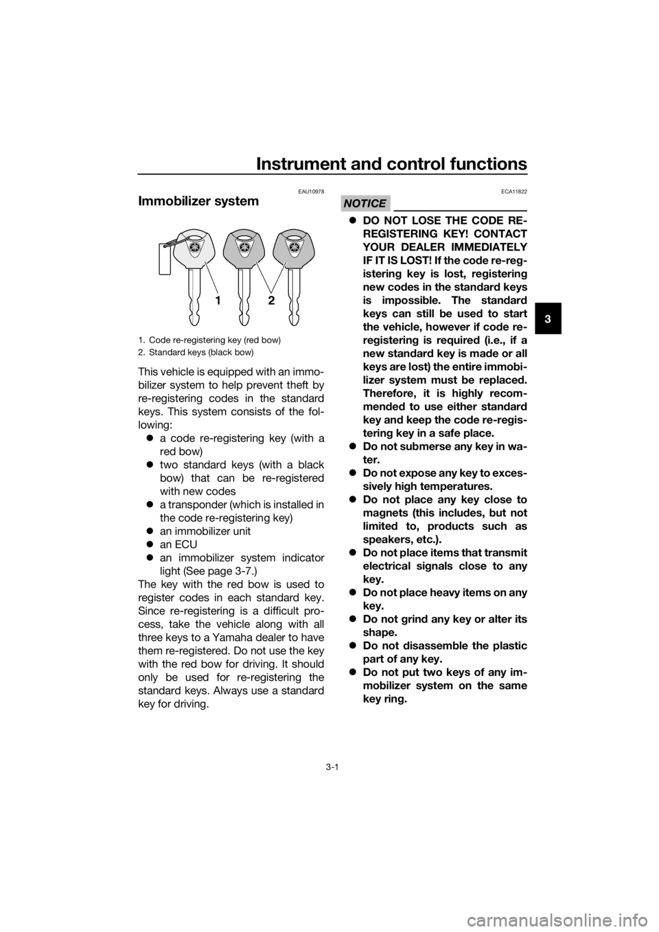
This vehicle is equipped with an immo-
bilizer system to help prevent theft by
re-registering codes in the standard
keys. This system consists of the fol-
lowing:
a code re-registering key (with a
red bow)
two standard keys (with a black
bow) that can be re-registered
with new codes
a transponder (which is installed in
the code re-registering key)
an immobilizer unit
an ECU
an immobilizer system indicator
light (See page 3-7.)
The key with the red bow is used to
register codes in each standard key.
Since re-registering is a difficult pro-
cess, take the vehicle along with all
three keys to a Yamaha dealer to have
them re-registered. Do not use the key
with the red bow for driving. It should
only be used for re-registering the
standard keys. Always use a standard
key for driving.
NOTICE
ECA11822
DO NOT LOSE THE CODE RE-
REGISTERING KEY! CONTACT
YOUR DEALER IMMEDIATELY
IF IT IS LOST! If the co de re-reg -
isterin g key is lost, reg istering
new co des in the stan dar d keys
is impossi ble. The stan dar d
keys can still be used to start
the vehicle, however if co de re-
re gisterin g is require d (i.e., if a
new stan dar d key is ma de or all
keys are lost) the entire immob i-
lizer system must be replaced .
Therefore, it is hi ghly recom-
mend ed to use either stan dar d
key an d keep the co de re-re gis-
tering key in a safe place.
Do not su bmerse any key in wa-
ter.
Do not expose any key to exces-
sively hig h temperatures.
Do not place any key close to
ma gnets (this includ es, but not
limite d to, pro ducts such as
speakers, etc.).
Do n
ot place items that transmit
electrical si gnals close to any
key.
Do not place heavy items on any
key.
Do not g rind any key or alter its
shape.
Do not d isassemble the plastic
part of any key.
Do not put two keys of any im-
mo bilizer system on the same
key rin g.
1. Code re-registering key (red bow)
2. Standard keys (black bow)
UB95E0E0.book Page 1 Friday, February 19, 2016 2:15 PM
Page 40 of 126
Instrument and control functions
3-26
3
EAU55491
YCC-S system
This vehicle features the YCC-S
(Yamaha Chip Controlled-Shift) sys-
tem.
The basic function of this system al-
lows the rider to shift gears without the
use of a clutch lever. Furthermore, a
hand shift lever is equipped on the
handlebar, allowing the rider to shift
gears with either the foot-operated
shift pedal or the hand-operated shift
lever. (See page 3-27.)
When the engine is started and the
shift pedal or the shift lever is moved, a
signal is sent to the MCU (Motor Con-
trol Unit) which disengages the clutch,
the ECU (Engine Control Unit) then ad-
justs the electronic throttle valve, the
gear shift is made and then the clutch
is re-engaged once the engine is run-
ning at the proper speed. Clutch en-
gagement is controlled optimally by
the MCU according to engine r/min,
engine requirements, and riding condi-
tions.
TIP
This is not an automatic transmission,
only the clutch system is automatic.
The gears must be shifted by the rider
except when stopping the vehicle
while the stop mode function is activat-
ed.
See “Stop mode function switch” (See
page 3-25.) and OPERATION AND IM-
PORTANT RIDING POINTS (See page
5-1.) for further explanation of this sys-
tem.
EAU40496
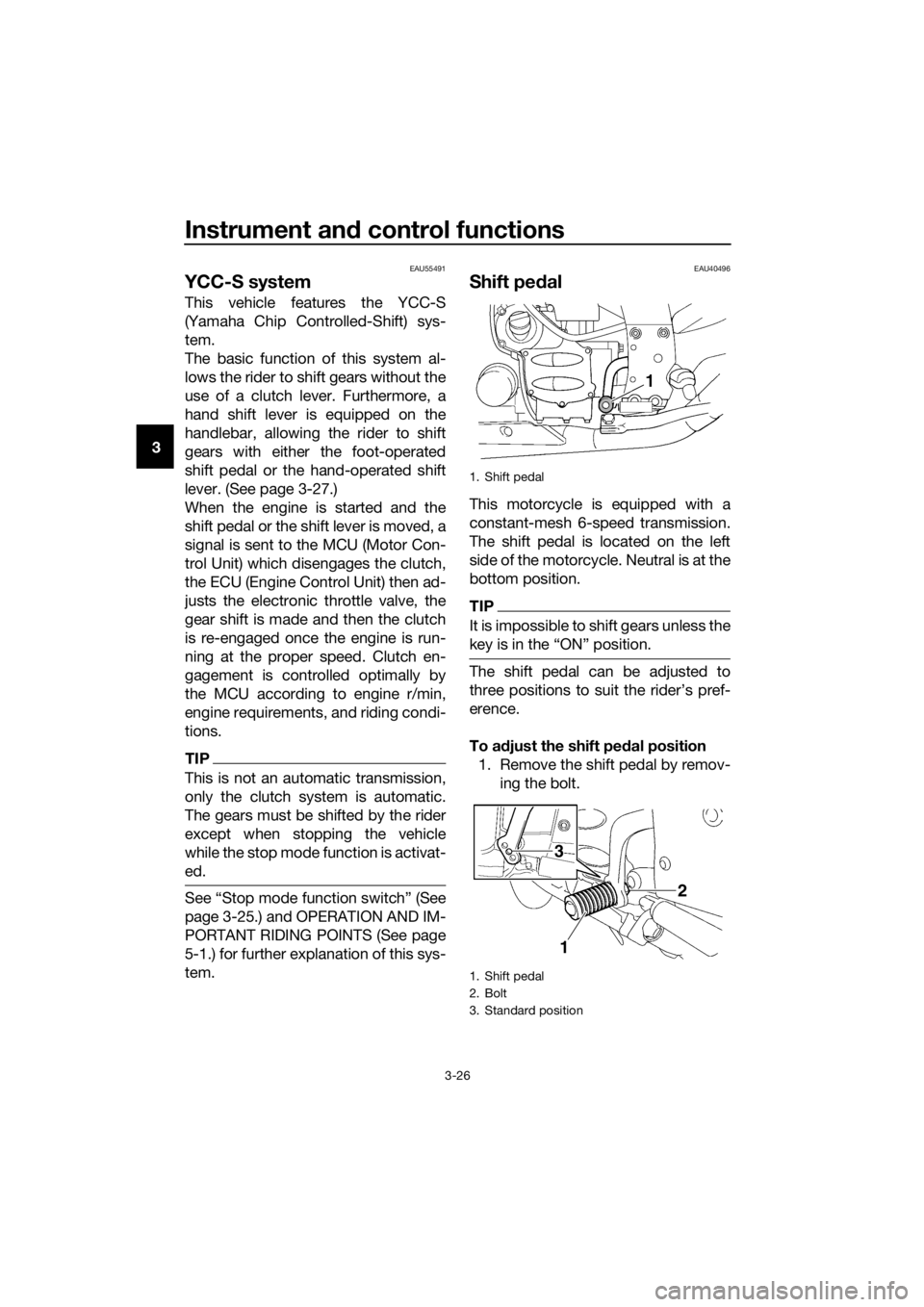
Shift pe dal
This motorcycle is equipped with a
constant-mesh 6-speed transmission.
The shift pedal is located on the left
side of the motorcycle. Neutral is at the
bottom position.
TIP
It is impossible to shift gears unless the
key is in the “ON” position.
The shift pedal can be adjusted to
three positions to suit the rider’s pref-
erence.
To a djust the shift ped al position
1. Remove the shift pedal by remov- ing the bolt.
1. Shift pedal
1. Shift pedal
2. Bolt
3. Standard position
3
1
2
UB95E0E0.book Page 26 Friday, February 19, 2016 2:15 PM
Page 43 of 126
Instrument and control functions
3-29
3
EAU73181
ABS
This model’s anti-lock brake system
(ABS) features a dual electronic control
system, which acts on the front and
rear brakes independently.
Operate the brakes with ABS as you
would conventional brakes. If the ABS
is activated, a pulsating sensation may
be felt at the brake lever or brake ped-
al. In this situation, continue to apply
the brakes and let the ABS work; do
not “pump” the brakes as this will re-
duce braking effectiveness.
WARNING
EWA16051
Always keep a sufficient d istance
from the vehicle ahead to match the
ri din g speed even with ABS.
The ABS performs b est with
lon g b rakin g d istances.
On certain surfaces, such as
rou gh or g ravel roa ds, the b rak-
in g d istance may be lon ger with
the ABS than without.
The ABS is monitored by an ECU,
which will revert the system to conven-
tional braking if a malfunction occurs.
TIP
The ABS performs a self-diagno-
sis test each time the vehicle first
starts off after the key is turned to
“ON” and the vehicle has traveled
at a speed of 10 km/h (6 mi/h) or
higher. During this test, a “click-
ing” noise may be heard from the
hydraulic control unit, and if the
brake lever or brake pedal is even
slightly applied, a vibration can be
felt at the lever and pedal, but this
does not indicate a malfunction.
This ABS has a test mode which
allows the owner to experience
the pulsation at the brake lever or
brake pedal when the ABS is op-
erating. However, special tools are
required, so please consult your
Yamaha dealer.
NOTICE
ECA16831
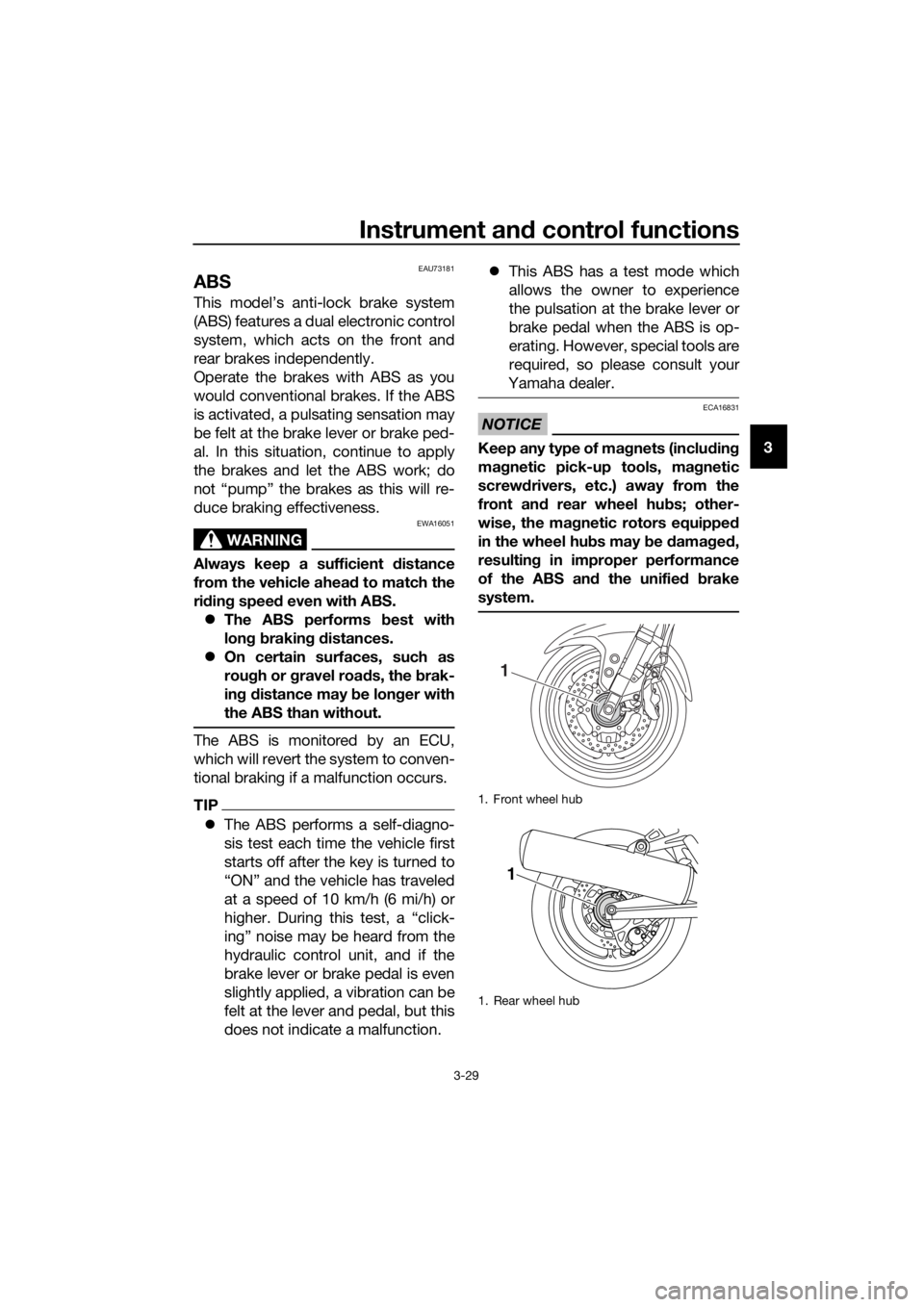
Keep any type of mag nets (including
ma gnetic pick-up tools, mag netic
screw drivers, etc.) away from the
front an d rear wheel hu bs; other-
wise, the ma gnetic rotors equippe d
in the wheel hu bs may b e damag ed ,
resultin g in improper performance
of the ABS an d the unifie d b rake
system.
1. Front wheel hub
1. Rear wheel hub
1
1
UB95E0E0.book Page 29 Friday, February 19, 2016 2:15 PM
Page 46 of 126

Instrument and control functions
3-32
3
EAU13222
Fuel
Make sure there is sufficient gasoline in
the tank.
WARNING
EWA10882
Gasoline an d g asoline vapors are
extremely flamma ble. To avoi d fires
an d explosions an d to re duce the
risk of injury when refuelin g, follow
these instructions.
1. Before refueling, turn off the en- gine and be sure that no one is sit-
ting on the vehicle. Never refuel
while smoking, or while in the vi-
cinity of sparks, open flames, or
other sources of ignition such as
the pilot lights of water heaters
and clothes dryers.
2. Do not overfill the fuel tank. When refueling, be sure to insert the
pump nozzle into the fuel tank filler
hole. Stop filling when the fuel
reaches the bottom of the filler
tube. Because fuel expands when
it heats up, heat from the engine or
the sun can cause fuel to spill out
of the fuel tank. 3. Wipe up any spilled fuel immedi-
ately. NOTICE: Immediately
wipe off spille d fuel with a clean,
d ry, soft cloth, since fuel may
d eteriorate painte d surfaces or
plastic parts.
[ECA10072]
4. Be sure to securely close the fuel tank cap.
WARNING
EWA15152
Gasoline is poisonous an d can
cause injury or death. Han dle gaso-
line with care. Never siphon gasoline
b y mouth. If you shoul d swallow
some gasoline or inhale a lot of gas-
oline vapor, or get some gasoline in
your eyes, see your doctor imme di-
ately. If gasoline spills on your skin,
wash with soap an d water. If gaso-
line spills on your clothin g, chan ge
your clothes.
EAU49743
NOTICE
ECA11401
Use only unlea ded g asoline. The use
of lead ed g asoline will cause severe
d amag e to internal en gine parts,
such as the valves an d piston rin gs,
as well as to the exhaust system.
Your Yamaha engine has been de-
signed to use regular unleaded gaso-
line with a research octane number of
1. Fuel tank filler tube
2. Maximum fuel level
Recommen ded fuel:
Regular unleaded gasoline (Gasohol
[E10] acceptable)
Fuel tank capacity: 25 L (6.6 US gal, 5.5 Imp.gal)
Fuel reserve amount:
5.5 L (1.45 US gal, 1.21 Imp.gal)
UB95E0E0.book Page 32 Friday, February 19, 2016 2:15 PM
Page 49 of 126
Instrument and control functions
3-35
3
Ri
der seat
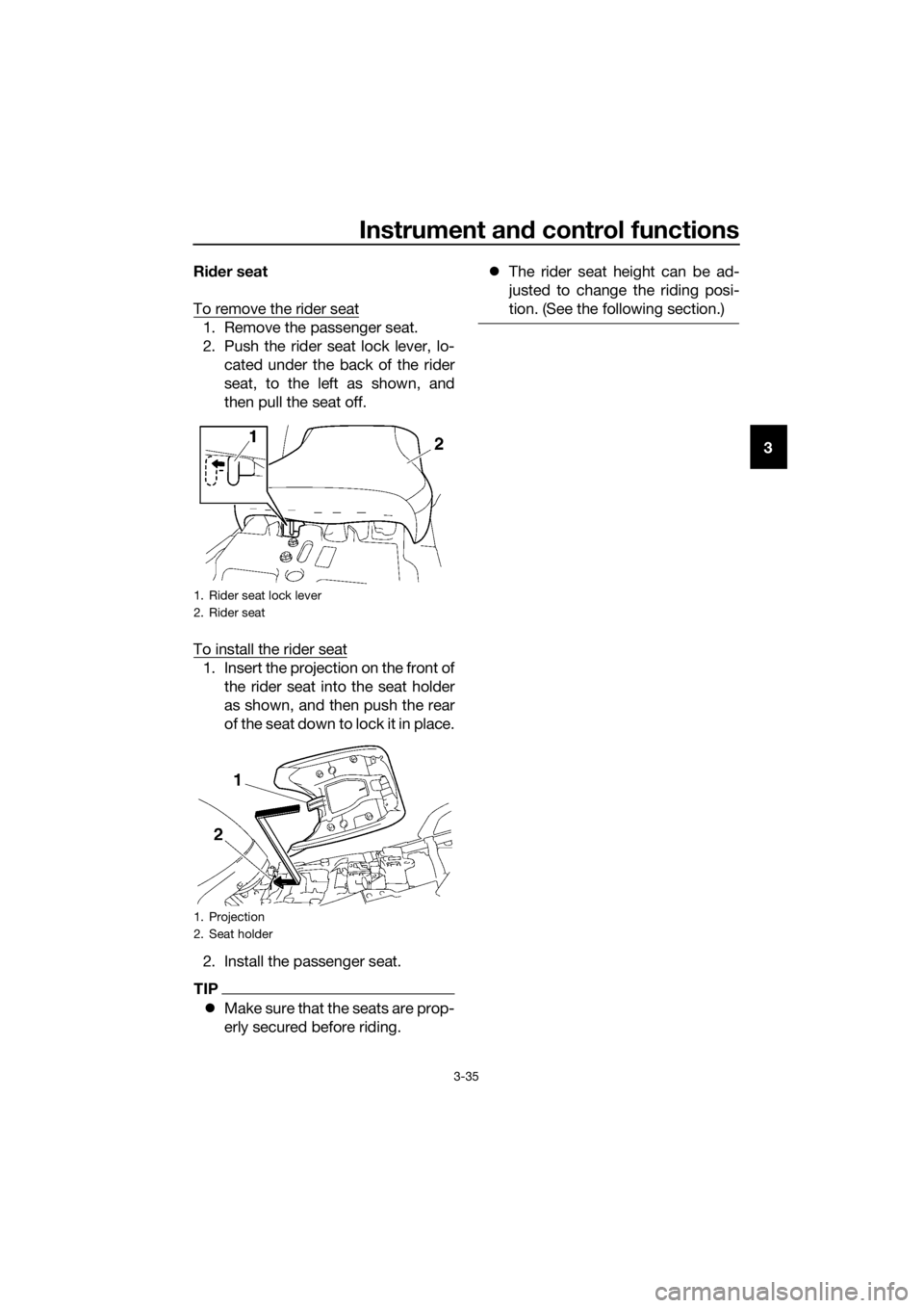
To remove the rider seat
1. Remove the passenger seat.
2. Push the rider seat lock lever, lo- cated under the back of the rider
seat, to the left as shown, and
then pull the seat off.
To install the rider seat
1. Insert the projection on the front of the rider seat into the seat holder
as shown, and then push the rear
of the seat down to lock it in place.
2. Install the passenger seat.
TIP
Make sure that the seats are prop-
erly secured before riding.
The rider seat height can be ad-
justed to change the riding posi-
tion. (See the following section.)
1. Rider seat lock lever
2. Rider seat
1. Projection
2. Seat holder
UB95E0E0.book Page 35 Friday, February 19, 2016 2:15 PM
Page 51 of 126
Instrument and control functions
3-37
3
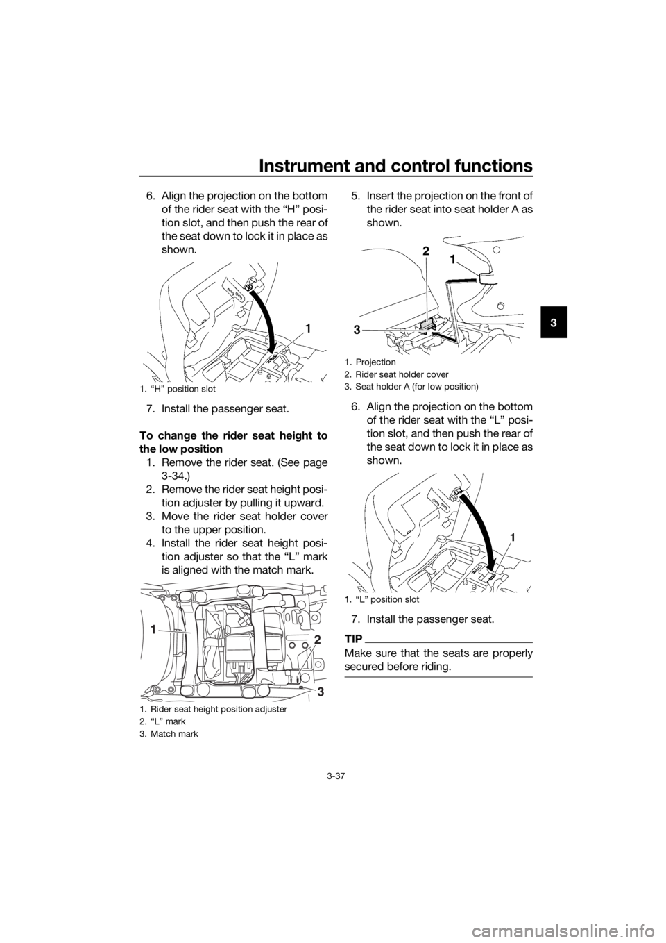
6. Align the projection on the bottom
of the rider seat with the “H” posi-
tion slot, and then push the rear of
the seat down to lock it in place as
shown.
7. Install the passenger seat.
To chan ge the rid er seat hei ght to
the low position 1. Remove the rider seat. (See page 3-34.)
2. Remove the rider seat height posi- tion adjuster by pulling it upward.
3. Move the rider seat holder cover to the upper position.
4. Install the rider seat height posi- tion adjuster so that the “L” mark
is aligned with the match mark. 5. Insert the projection on the front of
the rider seat into seat holder A as
shown.
6. Align the projection on the bottom of the rider seat with the “L” posi-
tion slot, and then push the rear of
the seat down to lock it in place as
shown.
7. Install the passenger seat.
TIP
Make sure that the seats are properly
secured before riding.
1. “H” position slot
1. Rider seat height position adjuster
2. “L” mark
3. Match mark
HL
12
3
1. Projection
2. Rider seat holder cover
3. Seat holder A (for low position)
1. “L” position slot
12
3
UB95E0E0.book Page 37 Friday, February 19, 2016 2:15 PM
Page 94 of 126
Periodic maintenance an d a djustment
6-20
6
TIP
The tire tread depth limits may differ
from country to country. Always com-
ply with the local regulations.
WARNING
EWA10472
Have a Yamaha dealer replace
excessively worn tires. Besi des
b ein g ille gal, operatin g the vehi-
cle with excessively worn tires
d ecreases ri din g sta bility an d
can lead to loss of control.
The replacement of all wheel
and b rake-relate d parts, inclu d-
in g the tires, shoul d b e left to a
Yamaha dealer, who has the
necessary professional knowl-
e dge an d experience to do so.
Ride at mo derate speed s after
chan gin g a tire since the tire
surface must first be “ broken
in” for it to d evelop its optimal
characteristics.
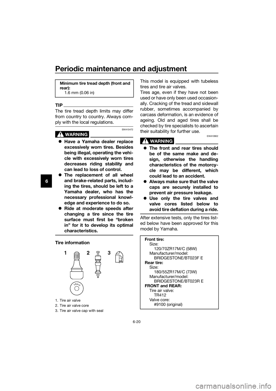
Tire information This model is equipped with tubeless
tires and tire air valves.
Tires age, even if they have not been
used or have only been used occasion-
ally. Cracking of the tread and sidewall
rubber, sometimes accompanied by
carcass deformation, is an evidence of
ageing. Old and aged tires shall be
checked by tire specialists to ascertain
their suitability for further use.
WARNING
EWA10902
The front an d rear tires shoul d
b e of the same make an d d e-
si gn, otherwise the han dlin g
characteristics of the motorcy-
cle may b e different, which
coul d lea d to an acci dent.
Always make sure that the valve
caps are securely installe d to
prevent air pressure leakag e.
Use only the tire valves an d
valve cores liste d below to
avoi d tire deflation during a ride.
After extensive tests, only the tires list-
ed below have been approved for this
model by Yamaha.
Minimum tire trea d d epth (front an d
rear): 1.6 mm (0.06 in)
1. Tire air valve
2. Tire air valve core
3. Tire air valve cap with seal
Front tire:Size:
120/70ZR17M/C (58W)
Manufacturer/model: BRIDGESTONE/BT023F E
Rear tire: Size:180/55ZR17M/C (73W)
Manufacturer/model: BRIDGESTONE/BT023R E
FRONT an d REAR:
Tire air valve: TR412
Valve core:
#9100 (original)
UB95E0E0.book Page 20 Friday, February 19, 2016 2:15 PM