2016 YAMAHA FJR1300AS light
[x] Cancel search: lightPage 89 of 126

Periodic maintenance an d a djustment
6-15
6
4. Install the final gear oil drain bolt
and its new gasket, and then tight-
en the bolt to the specified torque.
5. Refill with the recommended final gear oil to the brim of the filler
hole.
6. Check the oil filler bolt gasket for damage, and replace it if neces-
sary.
7. Install the oil filler bolt and its gas- ket, and then tighten the bolt to
the specified torque.
8. Check the final gear case for oil leakage. If oil is leaking, check for
the cause.
EAU20071
Coolant
The coolant level should be checked
before each ride. In addition, the cool-
ant must be changed at the intervals
specified in the periodic maintenance
and lubrication chart.
EAU54163To check the coolant level1. Place the vehicle on the center- stand.
TIP
The coolant level must be
checked on a cold engine since
the level varies with engine tem-
perature.
Make sure that the vehicle is posi-
tioned straight up when checking
the coolant level. A slight tilt to the
side can result in a false reading.
2. Remove the left cowling vent pan-
el. (See page 3-41.)
3. Check the coolant level in the coolant reservoir.
TIP
The coolant should be between the
minimum and maximum level marks.
1. Final gear oil filler bolt
2. Gasket
3. Final gear oil drain bolt
Tightening torque:
Final gear oil drain bolt:
23 Nm (2.3 m·kgf, 17 ft·lbf)
Recommen ded final gear oil:
Yamaha genuine shaft drive gear oil
SAE 80W-90 API GL-5
Oil quantity:
0.20 L (0.21 US qt, 0.18 Imp.qt)
Ti ghtening torque:
Final gear oil filler bolt: 23 Nm (2.3 m·kgf, 17 ft·lbf)
1
2
32
1. Coolant reservoir
2. Maximum level mark
3. Minimum level mark
2
1 3
UB95E0E0.book Page 15 Friday, February 19, 2016 2:15 PM
Page 97 of 126

Periodic maintenance an d a djustment
6-23
6
EAU22283
Brake li ght switches
The brake light, which is activated by
the brake pedal and brake lever,
should come on just before braking
takes effect. Since the brake light
switches are components of the cruise
control system, they must be adjusted
by a Yamaha dealer, who has the nec-
essary professional knowledge and ex-
perience.
EAU22393
Checkin g the front an d rear
b rake pa ds
The front and rear brake pads must be
checked for wear at the intervals spec-
ified in the periodic maintenance and
lubrication chart.
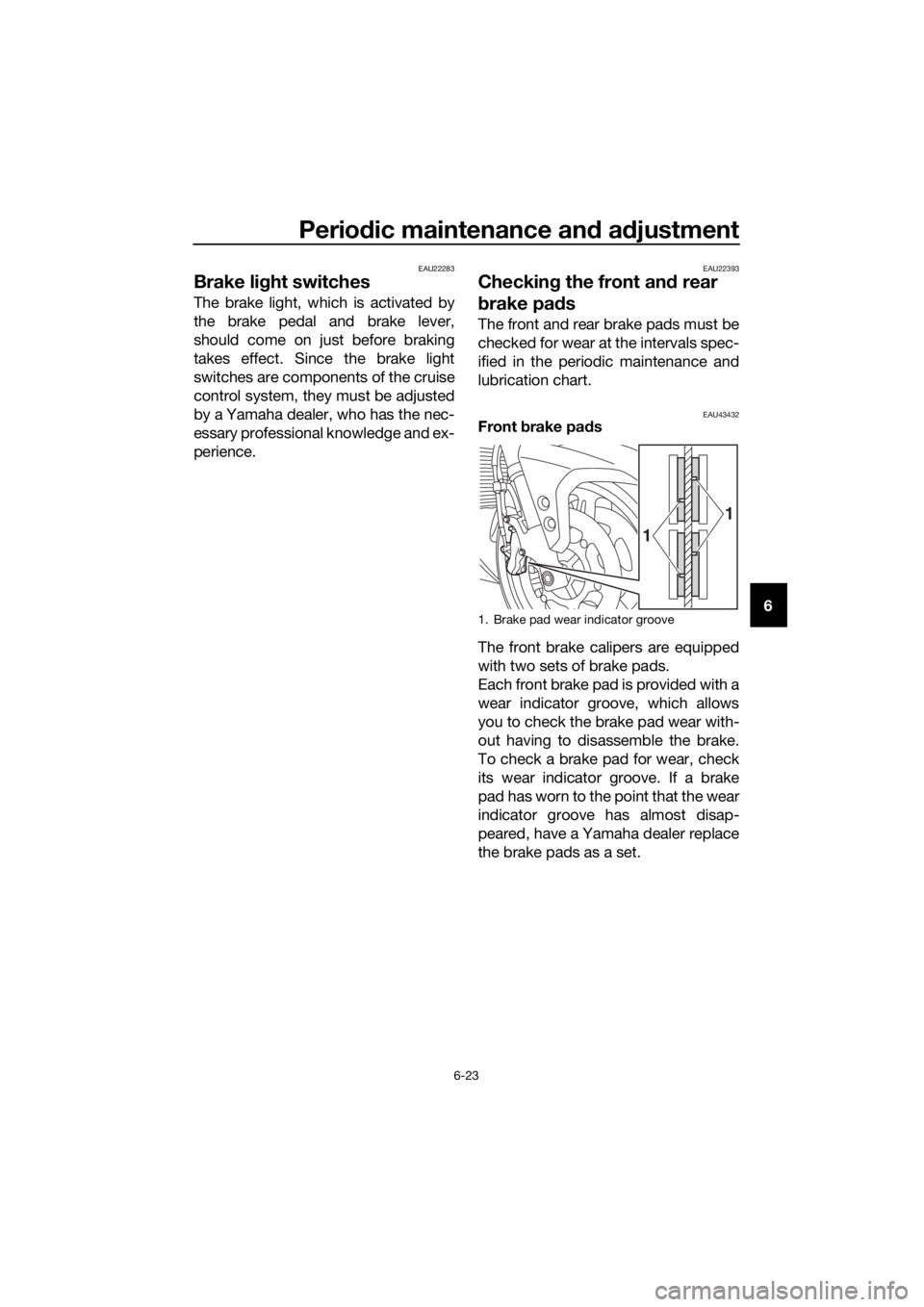
EAU43432Front brake pad s
The front brake calipers are equipped
with two sets of brake pads.
Each front brake pad is provided with a
wear indicator groove, which allows
you to check the brake pad wear with-
out having to disassemble the brake.
To check a brake pad for wear, check
its wear indicator groove. If a brake
pad has worn to the point that the wear
indicator groove has almost disap-
peared, have a Yamaha dealer replace
the brake pads as a set.
1. Brake pad wear indicator groove
1
1
UB95E0E0.book Page 23 Friday, February 19, 2016 2:15 PM
Page 107 of 126

Periodic maintenance an d a djustment
6-33
6
EAU54515
Replacin g the fuses
The fuse boxes and individual fuses
are located under panel A. (See page
6-7.)
If a fuse is blown, replace it as follows.1. Turn the key to “OFF” and turn off the electrical circuit in question.
2. Remove the blown fuse, and then install a new fuse of the specified
amperage. WARNING! Do not
use a fuse of a hi gher ampera ge
ratin g than recommen ded to
avoi d causin g extensive dam-
a g e to the electrical system an d
possi bly a fire.
[EWA15132]
1. Main fuse
2. Spare fuse
3. Cruise control fuse
4. Brake light fuse
5. Fuse box
6. Main fuse 2
5
1
3
4
2
5 26
1. ABS motor fuse
2. ABS solenoid fuse
3. Fuel injection system fuse
4. Backup fuse (for clock and immobilizer sys-
tem)
5. Electronic throttle valve fuse
6. Headlight fuse
7. Spare fuse
8. YCC-S motor control fuse
9. Suspension fuse
10.Signaling system fuse
11.Terminal fuse 1 (for auxiliary DC jack)
12.ABS control unit fuse
13.Ignition fuse
14.Right radiator fan motor fuse
15.Left radiator fan motor fuse
16.Hazard fuse
17.Windshield motor fuse
15 7
11
10121314
71716
8
1
9
234
5
67
7
UB95E0E0.book Page 33 Friday, February 19, 2016 2:15 PM
Page 108 of 126

Periodic maintenance an d a djustment
6-34
6
3. Turn the key to “ON” and turn onthe electrical circuit in question to
check if the device operates.
4. If the fuse immediately blows again, have a Yamaha dealer
check the electrical system.
EAU72980
Vehicle li ghts
This model is equipped with full-LED
lighting. There are no user replaceable
bulbs.
If a light does not come on, check the
fuses and then have a Yamaha dealer
check the vehicle.
NOTICE
ECA16581
Do not affix any type of tinted film or
stickers to the head light lens.
Specifie d fuses:
Main fuse: 50.0 A
Main fuse 2:
30.0 A
Te r m i n a l f u s e 1 : 3.0 A
Headlight fuse: 7.5 A
Brake light fuse:
1.0 A
Signaling system fuse: 7.5 A
Ignition fuse: 20.0 A
Radiator fan motor fuse:
10.0 A × 2
Backup fuse: 7.5 A
Hazard fuse: 7.5 A
Fuel injection system fuse:
15.0 A
ABS control unit fuse: 7.5 A
ABS motor fuse: 30.0 A
ABS solenoid fuse:
20.0 A
Suspension fuse: 15.0 A
YCC-S motor control fuse: 30.0 A
Cruise control fuse:
1.0 A
Windshield motor fuse: 20.0 A
Electronic throttle valve fuse: 7.5 A
UB95E0E0.book Page 34 Friday, February 19, 2016 2:15 PM
Page 113 of 126

Motorcycle care and stora ge
7-2
7
structed
. Also, thorou ghly rinse
the area off with water, immed i-
ately dry it, an d then apply a cor-
rosion protection spray.
Improper cleanin g can damag e
plastic parts (such as cowlin gs,
panels, win dshield s, head light
lenses, meter lenses, etc.) an d
the mufflers. Use only a soft,
clean cloth or spon ge with wa-
ter to clean plastic. However, if
the plastic parts cannot be thor-
ou ghly cleaned with water, di-
lute d mil d d eter gent with water
may be used . Be sure to rinse
off any d etergent resi due usin g
plenty of water, as it is harmful
to plastic parts.
Do not use any harsh chemical
prod ucts on plastic parts. Be
sure to avoi d usin g cloths or
spon ges which have b een in
contact with stron g or a brasive
cleanin g prod ucts, solvent or
thinner, fuel ( gasoline), rust re-
movers or inhi bitors,
b rake flui d,
antifreeze or electrolyte.
Do not use hi gh-pressure wash-
ers or steam-jet cleaners since
they cause water seepag e and
d eterioration in the followin g ar-
eas: seals (of wheel an d swin g-
arm bearin gs, fork an d b rakes),
electric components (couplers,
connectors, instruments,
switches an d li ghts), breather
hoses an d vents.
For motorcycles equippe d with
a win dshiel d: Do not use stron g
cleaners or har d spon ges as
they will cause dullin g or
scratching . Some cleanin gcompoun
ds for plastic may
leave scratches on the wind -
shiel d. Test the prod uct on a
small hidden part of the win d-
shiel d to make sure that it does
not leave any marks. If the win d-
shiel d is scratche d, use a quality
plastic polishin g compoun d af-
te r
washin g.
After normal use
Remove dirt with warm water, a mild
detergent, and a soft, clean sponge,
and then rinse thoroughly with clean
water. Use a toothbrush or bottlebrush
for hard-to-reach areas. Stubborn dirt
and insects will come off more easily if
the area is covered with a wet cloth for
a few minutes before cleaning.
After riding in the rain, near the sea or
on salt-sprayed roads
Since sea salt or salt sprayed on roads
during winter are extremely corrosive
in combination with water, carry out
the following steps after each ride in
the rain, near the sea or on salt-
sprayed roads.
TIP
Salt sprayed on roads in the winter
may remain well into spring.
1. Clean the motorcycle with cold
water and a mild detergent, after
the engine has cooled down.
NOTICE: Do not use warm wa-
ter since it increases the corro-
sive action of the salt.
[ECA10792]
UB95E0E0.book Page 2 Friday, February 19, 2016 2:15 PM
Page 114 of 126

Motorcycle care and stora ge
7-3
7 2. After drying the motorcycle, apply
a corrosion protection spray on all
metal, including chrome- and
nickel-plated, surfaces to prevent
corrosion.
Windshield cleaning
Avoid using any alkaline or strong acid
cleaner, gasoline, brake fluid, or any
other solvent. Clean the windshield
with a cloth or sponge dampened with
a neutral detergent, and after cleaning,
thoroughly wash it off with water. For
additional cleaning, use Yamaha Wind-
shield Cleaner or other quality cleaner.
Some cleaning compounds for plastics
may leave scratches on surfaces of the
windshield. Before using them, make a
test by polishing an area which does
not affect your visibility.
After cleanin g
1. Dry the motorcycle with a chamois or an absorbing cloth.
2. Use a chrome polish to shine chrome, aluminum and stainless-
steel parts, including the exhaust
system. (Even the thermally in-
duced discoloring of stainless-
steel exhaust systems can be re-
moved through polishing.)
3. To prevent corrosion, it is recom- mended to apply a corrosion pro-
tection spray on all metal,
including chrome- and nickel-plat-
ed, surfaces.
4. Use spray oil as a universal clean- er to remove any remaining dirt.
5. Touch up minor paint damage caused by stones, etc.
6. Wax all painted surfaces. 7. Let the motorcycle dry completely
before storing or covering it.
WARNING
EWA11132
Contaminants on the brakes or tires
can cause loss of control. Make sure that there is no oil or
wax on the brakes or tires.
If necessary, clean the b rake
d iscs an d b rake linin gs with a
re gular brake disc cleaner or
acetone, an d wash the tires with
warm water an d a mil d d eter-
g ent. Before ri din g at hi gher
speed s, test the motorcycle’s
b rakin g performance an d cor-
nering b ehavior.
NOTICE
ECA10801
Apply spray oil an d wax spar-
in gly an d make sure to wipe off
any excess.
Never apply oil or wax to any
rubber an d plastic parts, but
treat them with a suitab le care
prod uct.
Avoi d using abrasive polishin g
compoun ds as they will wear
away the paint.
TIP
Consult a Yamaha dealer for ad-
vice on what products to use.
Washing, rainy weather or humid
climates can cause the headlight
lens to fog. Turning the headlight
on for a short period of time will
help remove the moisture from the
lens.
UB95E0E0.book Page 3 Friday, February 19, 2016 2:15 PM
Page 119 of 126

Specifications
8-3
8
Battery:
Model:GT14B-4
Voltage, capacity:
12 V, 12.0 Ah (10 HR)
Bul b watta ge × quantity:
Headlight:
LED
Brake/tail light:
LED
Front turn signal light: LED
Rear turn signal light: LED
Auxiliary light: LED
License plate light:
LED
Meter lighting: LED
Neutral indicator light: LED
High beam indicator light:
LED
Oil level warning light: LED
Turn signal indicator light: LED
Engine trouble warning light:
LED
ABS warning light: LED
Cruise control “SET” indicator light: LED
Cruise control “ON” indicator light:
LED
Immobilizer system indicator light: LED
Traction control system indicator/warning
light: LED
Shift down indicator light: LED
YCC-S system warning light:
LED
Suspension warning light: LED
Fuse(s):
Main fuse:
50.0 A Main fuse 2:
30.0 A
Terminal fuse 1: 3.0 A
Headlight fuse:
7.5 A
Brake light fuse: 1.0 A
Signaling system fuse: 7.5 A
Ignition fuse:
20.0 A
Radiator fan motor fuse: 10.0 A × 2
Hazard fuse: 7.5 A
Fuel injection system fuse: 15.0 A
ABS control unit fuse:
7.5 A
ABS motor fuse: 30.0 A
ABS solenoid fuse: 20.0 A
Suspension fuse:
15.0 A
Cruise control fuse: 1.0 A
YCC-S motor control fuse: 30.0 A
Backup fuse:
7.5 A
Windshield motor fuse: 20.0 A
Electronic throttle valve fuse: 7.5 A
UB95E0E0.book Page 3 Friday, February 19, 2016 2:15 PM
Page 122 of 126

10-1
10
Index
A
ABS ....................................................... 3-29
ABS warning light ................................... 3-5
Accessory box ...................................... 3-39
Air filter element .................................... 6-17
Auxiliary DC jack ................................... 3-50
B
Battery .................................................. 6-31
Brake and shift pedals, checking and
lubricating ........................................... 6-27
Brake and YCC-S clutch fluid levels, checking ............................................. 6-24
Brake and YCC-S clutch fluids, changing ............................................. 6-26
Brake lever ............................................ 3-28
Brake lever, checking and lubricating ........................................... 6-28
Brake lever free play, checking............. 6-22
Brake light switches.............................. 6-23
Brake pedal........................................... 3-28
C
Cables, checking and lubricating ......... 6-26
Canister................................................. 6-11
Care ........................................................ 7-1
Catalytic converters .............................. 3-34
Centerstand and sidestand, checking and lubricating .................................... 6-28
Coolant ................................................. 6-15
Cornering lights .................................... 3-51
Cowling vents, opening and closing ..... 3-41
Cruise control indicator lights ................. 3-4
Cruise control switches ........................ 3-25
Cruise control system ............................. 3-8
D
Diagnostic connector.............................. 9-2
Dimmer/Pass switch ............................. 3-24
D-mode (drive mode) ............................ 3-23
E
Electronically adjustable suspension system warning light............................. 3-6
Engine break-in....................................... 5-6
Engine idling speed, checking .............. 6-17
Engine oil and oil filter cartridge ........... 6-11
Engine serial number .............................. 9-1
Engine trouble warning light ................... 3-5
F
Final gear oil.......................................... 6-14
Front and rear brake pads, checking.... 6-23
Front fork, checking .............................. 6-30
Fuel ....................................................... 3-32 Fuel consumption, tips for reducing ...... 5-5
Fuel tank cap ........................................ 3-31
Fuel tank overflow hose ....................... 3-33
Fuses, replacing ................................... 6-33
H
Handlebar position, adjusting .............. 3-40
Handlebar switches .............................. 3-24
Hand shift lever .................................... 3-27
Hazard switch....................................... 3-24
Headlight beams, adjusting.................. 3-40
High beam indicator light ....................... 3-4
Horn switch .......................................... 3-24
I
Identification numbers ............................ 9-1
Ignition circuit cut-off system............... 3-48
Immobilizer system ................................ 3-1
Immobilizer system indicator light.......... 3-7
Indicator lights and warning lights ......... 3-4
M
Main switch/steering lock....................... 3-2
Maintenance and lubrication, periodic ... 6-4
Maintenance, emission control
system.................................................. 6-3
Matte color, caution ............................... 7-1
Menu switch ......................................... 3-25
Model label ............................................. 9-1
Multi-function meter unit ...................... 3-11
N
Neutral indicator light ............................. 3-4
O
Oil level warning light ............................. 3-4
P
Panels, removing and installing.............. 6-7
Parking ................................................... 5-7
Part locations ......................................... 2-1
R
Rear suspension, lubricating ................ 6-29
Rear view mirrors ................................. 3-42
Rider seat height, adjusting.................. 3-36
S
Safety information .................................. 1-1
Seats .................................................... 3-34
Select switch ........................................ 3-25
Shift down indicator light ....................... 3-6
Shifting ................................................... 5-3
Shift pedal ............................................ 3-26
Sidestand ............................................. 3-47
Spark plugs, checking .......................... 6-10
Specifications ......................................... 8-1
Starting the engine ................................. 5-2
UB95E0E0.book Page 1 Friday, February 19, 2016 2:15 PM