Page 48 of 126
Instrument and control functions
3-34
3
EAU13447
Catalytic converters
This vehicle is equipped with catalytic
converters in the exhaust system.
WARNING
EWA10863
The exhaust system is hot after op-
eration. To prevent a fire hazar d or
b urns:
Do not park the vehicle near
possi ble fire hazard s such as
g rass or other materials that
easily burn.
Park the vehicle in a place
where pe destrians or chil dren
are not likely to touch the hot
exhaust system.
Make sure that the exhaust sys-
tem has coole d down before
d oin g any maintenance work.
Do not allow the en gine to id le
more than a few minutes. Lon g
i d lin g can cause a b uild-up of
heat.
NOTICE
ECA10702
Use only unlea ded g asoline. The use
of lead ed g asoline will cause unre-
pairab le dama ge to the catalytic
converter.
EAU39496
Seats
Passen ger seat
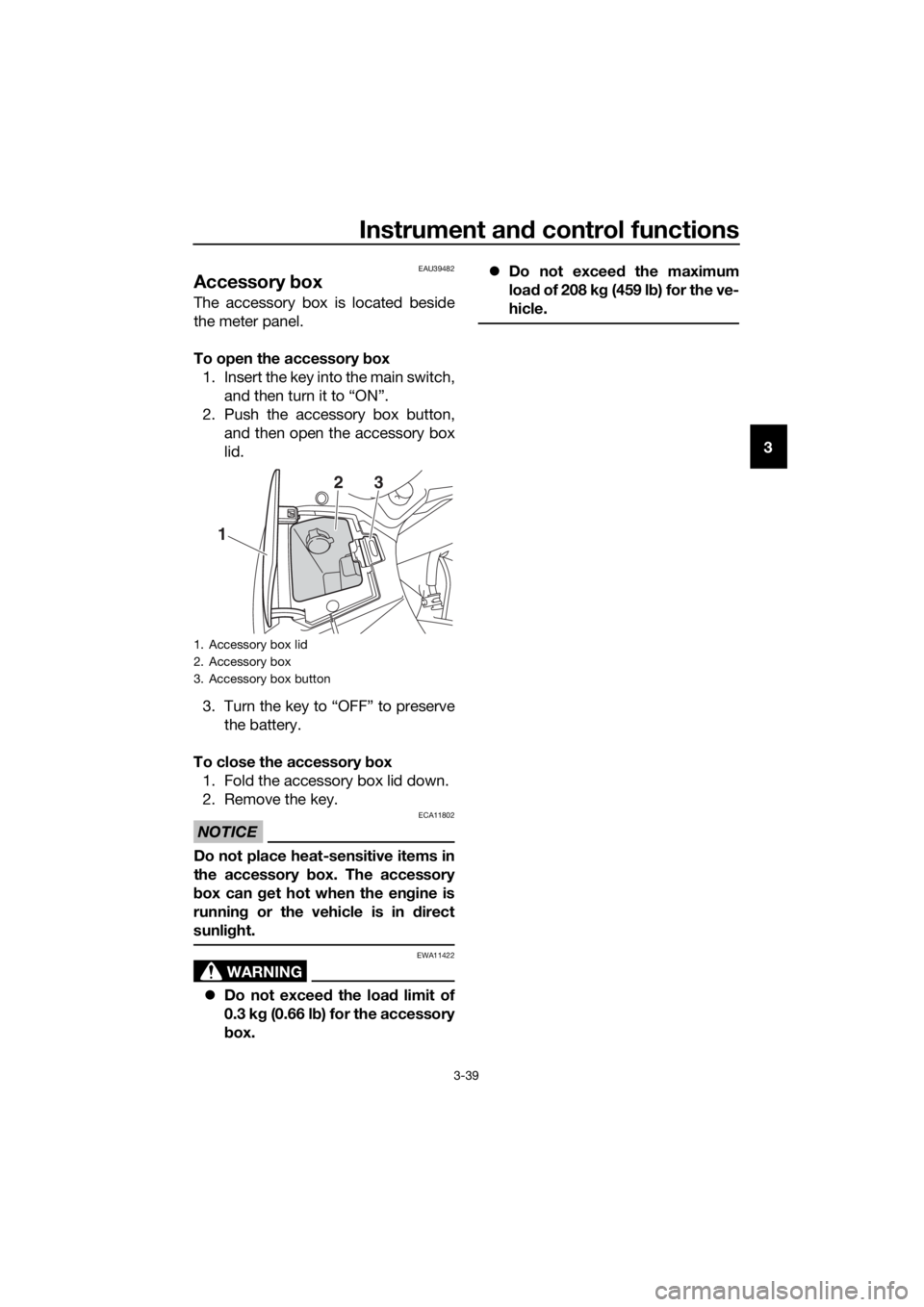
To remove the passenger seat
1. Insert the key into the seat lock, and then turn it counterclockwise.
2. Lift the front of the passenger seat and pull it forward.
To install the passenger seat
1. Insert the projections on the rear of the passenger seat into the seat
holders as shown, and then push
the front of the seat down to lock
it in place.
2. Remove the key.
1. Seat lock
2. Unlock.
1. Projection
2. Seat holder
1
2
UB95E0E0.book Page 34 Friday, February 19, 2016 2:15 PM
Page 52 of 126

Instrument and control functions
3-38
3
EAU73470
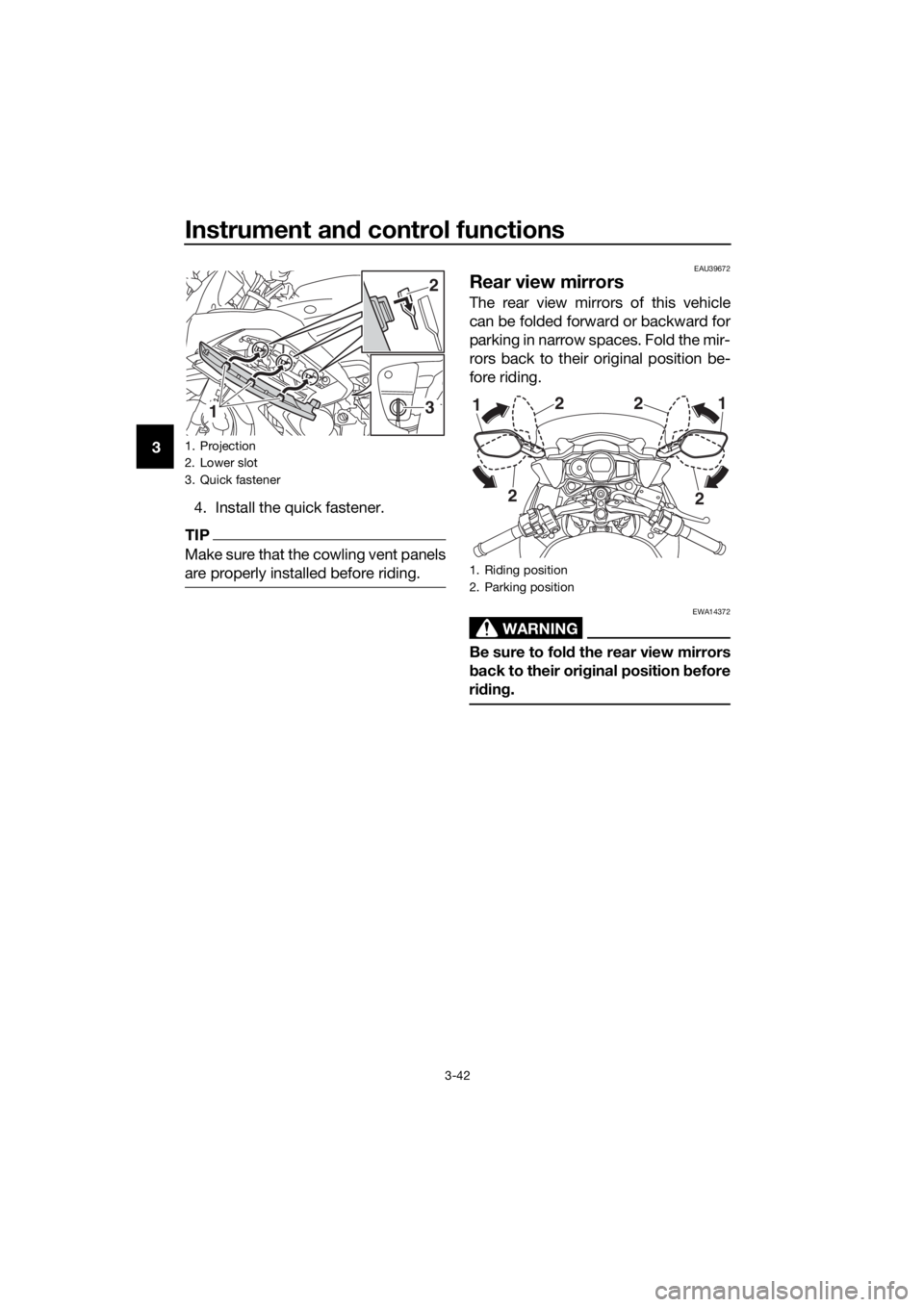
Stora ge compartment
The storage compartment is located
under the passenger seat. (See page
3-34.)
NOTICE
ECA23290
The IMU is not user servicea ble an d
very sensitive, so we a dvise a gainst
removin g the protective cover, plac-
in g any forei gn materials near the
IMU, or han dlin g the IMU d irectly.
Do not move or remount the
IMU to a d ifferent location.
Do not su bject the IMU to
stron g shocks or moisture.
Do not o bstruct the IMU breath-
er hole an d d o not clean it with
compresse d air.
When storing documents or other
items in the storage compartment, be
sure to wrap them in a plastic bag so
that they will not get wet. When wash-
ing the vehicle, be careful not to let any
water enter the storage compartment.
WARNING
EWA10962
Do not exceed the load limit of 3
k g (7 l b) for the stora ge com-
partment.
Do not exceed the maximum
loa d of 208 k g (459 l b) for the ve-
hicle.
1. Storage compartment
2. Protective cover
3. Inertial measurement unit (IMU)
1
2
23
UB95E0E0.book Page 38 Friday, February 19, 2016 2:15 PM
Page 53 of 126
Instrument and control functions
3-39
3
EAU39482
Accessory box
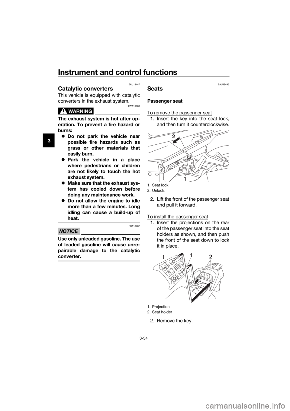
The accessory box is located beside
the meter panel.
To open the accessory box
1. Insert the key into the main switch, and then turn it to “ON”.
2. Push the accessory box button, and then open the accessory box
lid.
3. Turn the key to “OFF” to preserve the battery.
To close the accessory box
1. Fold the accessory box lid down.
2. Remove the key.
NOTICE
ECA11802
Do not place heat-sensitive items in
the accessory box. The accessory
b ox can g et hot when the en gine is
runnin g or the vehicle is in direct
sunli ght.
WARNING
EWA11422
Do not exceed the load limit of
0.3 k g (0.66 l b) for the accessory
b ox.
Do not exceed the maximum
loa d of 208 k g (459 l b) for the ve-
hicle.
1. Accessory box lid
2. Accessory box
3. Accessory box button
1
23
UB95E0E0.book Page 39 Friday, February 19, 2016 2:15 PM
Page 56 of 126
Instrument and control functions
3-42
3
4. Install the quick fastener.
TIP
Make sure that the cowling vent panels
are properly installed before riding.
EAU39672
Rear view mirrors
The rear view mirrors of this vehicle
can be folded forward or backward for
parking in narrow spaces. Fold the mir-
rors back to their original position be-
fore riding.
WARNING
EWA14372
Be sure to fol d the rear view mirrors
b ack to their ori ginal position before
ri din g.
1. Projection
2. Lower slot
3. Quick fastener
13
2
1. Riding position
2. Parking position
2
2
1
2 2
1
UB95E0E0.book Page 42 Friday, February 19, 2016 2:15 PM
Page 57 of 126

Instrument and control functions
3-43
3
EAU55424
A djustin g the front an d rear
suspension
This model is equipped with an elec-
tronically adjustable suspension sys-
tem. The preload of the rear shock
absorber and the damping forces of
both the front fork and rear shock ab-
sorber can be adjusted.
WARNING
EWA12423
Be sure to stop the vehicle before
makin g any settin g chan ges to the
multi-function meter unit. Chang ing
settin gs while ri din g can d istract the
operator an d increase the risk of an
acci dent.
Preloa d
When riding with luggage or a passen-
ger, use the preload adjusting function
to adjust the suspension system to
match the load. There are 4 preload
settings.
TIP
The preload adjusting function will
appear only when the engine is
running.
Changing the preload setting will
also adjust the front and rear sus-
pension damping forces accord-
ingly. See “Damping force” on
page 3-45 for more information.
About cold temperature opera-
tion:
• When using the preload adjust- ing function, there should be no
weight on the vehicle.
• When using the preload adjust- ing function at ambient temper-
atures near or below 0 °C (32
°F), to protect the preload ad- justing function motor, the elec-
tronically adjustable suspension
system warning light may come
on.
• The suspension will still operate as normal, only the preload ad-
justing function cannot be used.
• To reset the electronically ad- justable suspension system
warning light, wait approximate-
ly 6 minutes and then turn the
key to “OFF” or immediately
turn the key to “OFF” and then
wait 6 minutes.
• If the electronically adjustable suspension system warning
light remains on, have a
Yamaha dealer check the sus- pension system.
To adjust the preload
1. Turn the key to “ON”, start the en- gine, and then shift the transmis-
sion into neutral.
2. Push the menu switch “MENU” to switch the function display to the
preload adjusting function.
1. Function display
2. Preload adjusting function
3. Preload setting pictogram
GEAR
N
1
3
2
UB95E0E0.book Page 43 Friday, February 19, 2016 2:15 PM
Page 60 of 126

Instrument and control functions
3-46
3
3. Use the select switch to select“HARD”, “STD” or “SOFT”.
4. Push the menu switch “MENU”.
5. Use the select switch to select the desired level for the damping
force setting.
TIP
The damping force setting can be set to
7 levels (+3, +2, +1, 0, –1, –2 and –3).
“+3” is the hardest level and “–3” is the
softest level.
6. Push the menu switch “MENU”.
If the vehicle moves while you are ad-
justing the damping force, the informa-
tion display will change to the display
mode.
WARNING
EWA16421
The rear shock ab sorber assem bly
contains hi ghly pressurize d nitro gen
g as. Read and un derstan d the fol-
lowin g information before han dlin g
the shock a bsor ber assem bly.
Do not tamper with or attempt
to open the cylind er assembly.
Do not su bject the shock a b-
sor ber assem bly to an open
flame or other hi gh heat source.
This may cause the unit to ex-
plo de due to excessive g as
pressure.
1. Function display
2. Damping force adjusting function
1. Damping force setting
1. Damping force setting level
GEAR
N
STD 0
1
2
GEAR
N
HARD 01
GEAR
N
HARD
+31
1. Damping force adjusting function
2. Damping force setting
3. Preload setting pictogram
GEAR
N
HARD+3
GEAR
1
HARD+3
1
2
3
UB95E0E0.book Page 46 Friday, February 19, 2016 2:15 PM
Page 61 of 126

Instrument and control functions
3-47
3
Do not deform or damag e the
cylin der in any way. Cylin der
d amag e will result in poor
d ampin g performance.
Do not d ispose of a damag ed or
worn-out shock a bsor ber as-
sem bly yourself. Take the shock
a b sor ber assem bly to a Yamaha
d ealer for any service.
EAU55592
Si destan d
The sidestand is located on the left
side of the frame. Raise the sidestand
or lower it with your foot while holding
the vehicle upright.
TIP
The built-in sidestand switch is
part of the ignition circuit cut-off
system, which cuts the ignition in
certain situations. (See the follow-
ing section for an explanation of
the ignition circuit cut-off system.)
The sidestand switch is also part
of the YCC-S system. Shifting out
of neutral is impossible when the
sidestand is down.
WARNING
EWA10242
The vehicle must not be ri dden with
the si destan d d own, or if the si de-
stan d cannot b e properly move d up
(or does not stay up), otherwise the
si destan d coul d contact the g round
an d d istract the operator, resultin g
in a possi ble loss of control.
Yamaha’s ig nition circuit cut-off
system has been desi gne d to assist
the operator in fulfillin g the respon-
si bility of raisin g the si destan d b e-
fore startin g off. Therefore, check
this system re gularly an d have a
Yamaha dealer repair it if it does not
function properly.
UB95E0E0.book Page 47 Friday, February 19, 2016 2:15 PM
Page 63 of 126

Instrument and control functions
3-49
3
With the engine turned off:
1. Place the vehicle on the centerstand.
2.
Move the sidestand down.
3. Make sure that the start/engine stop switch is set to “ ”.
4. Turn the key to “ON”.
5. Shift the transmission into the neutral position.
6. Keep the front or rear brake applied.
7.
Push the “ ” side of the start/engine
stop switch.
Does the engine start?
With the engine still running:
8. Move the sidestand up.
9. Shift the transmission into gear.
10. Move the sidestand down.
Does the engine stall?
After the engine has stalled:
11. Move the sidestand up.
12. Release the brake.
13.
Push the “ ” side of the
start/engine stop switch.
Does the engine start?
The system is OK. The motorcycle can
be ridden.
The neutral switch, a brake light switch
or the YCC-S system may not be
working correctly.
The motorcycle should not be ridden
until checked by a Yamaha dealer.
The sidestand switch may not be
working correctly.
The motorcycle should not be ridden
until checked by a Yamaha dealer.
A brake light switch may not be working
correctly.
The motorcycle should not be ridden
until checked by a Yamaha dealer.
WARNING
The vehicle must be placed on the centerstand during this inspection.
If a malfunction is noted, have a Yamaha dealer check the system
before riding.
TIP
The traction control system
indicator/warning light “TCS” may come
on, but this is not a malfunction.
YES NO
YESNO
NOYES
UB95E0E0.book Page 49 Friday, February 19, 2016 2:15 PM